2008 SUZUKI SWIFT Indicator wiring
[x] Cancel search: Indicator wiringPage 1451 of 1496
Downloaded from www.Manualslib.com manuals search engine Immobilizer Control System: 10C-8
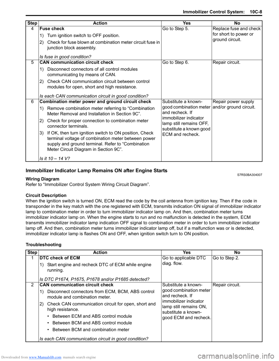
Immobilizer Indicator Lamp Remains ON after Engine StartsS7RS0BA304007
Wiring Diagram
Refer to “Immobilizer Control S ystem Wiring Circuit Diagram”.
Circuit Description
When the ignition switch is turned ON, ECM read the code by the coil antenna from ignition key. Then if the code in
transponder in the key match with the one registered with ECM, transmits indication ON signal of immobilizer indicator
lamp to combination meter in order to turn immobilizer indicator lamp on. And then, combination meter turns
immobilizer indicator lamp on. When th e engine starts to run and no malfunction is detected in the system, ECM
transmits immobilizer indicator lamp indication O FF signal to combination meter in order to turn immobilizer indicator
lamp off. And then, comb ination meter turns immobilizer indicator lamp off, but if a malfunction was or is detected,
immobilizer indicator lamp is flashes ON and OF F, when ignition switch turn to ON position.
Troubleshooting 4
Fuse check
1) Turn ignition switch to OFF position.
2) Check for fuse blown at combination meter circuit fuse in
junction block assembly.
Is fuse in good condition? Go to Step 5. Replace fuse and check
for short to power or
ground circuit.
5 CAN communication circuit check
1) Disconnect connectors of all control modules
communicating by means of CAN.
2) Check CAN communication circuit between control modules for open, short and high resistance.
Is each CAN communication circuit in good condition? Go to Step 6. Repair circuit.
6 Combination meter power and ground circuit check
1) Remove combination meter referring to “Combination
Meter Removal and Installation in Section 9C”.
2) Check for proper connection to combination meter connector terminals.
3) If OK, then turn ignition switch to ON position, Check terminal voltage of combination meter between power
supply and ground terminal. Refer to “Combination
Meter Circuit Diagram in Section 9C”.
Is it 10 – 14 V? Substitute a known-
good combination meter
and recheck. If
immobilizer indicator
lamp still remains OFF,
substitute a known good
ECM and recheck.
Repair power supply
and/or ground circuit.
Step Action Yes No
Step
Action YesNo
1 DTC check of ECM
1) Start engine and recheck DTC of ECM while engine
running.
Is DTC P1674, P1675, P1678 and/or P1685 detected? Go to applicable DTC
diag. flow.
Go to Step 2.
2 CAN communication circuit check
1) Disconnect connectors from ECM, BCM, ABS control
module and combination meter.
2) Check CAN communication circuit for open, short and high resistance.
• Between ECM and ABS control module
• Between BCM and ABS control module
• Between BCM and combination meter
Is each CAN communication circuit in good condition? Substitute a known-
good combination meter
and recheck. If
immobilizer indicator
lamp still remains ON,
substitute a known-
good ECM and recheck.
Repair circuit.
Page 1469 of 1496
Downloaded from www.Manualslib.com manuals search engine Keyless Start System: 10E-7
Schematic and Routing Diagram
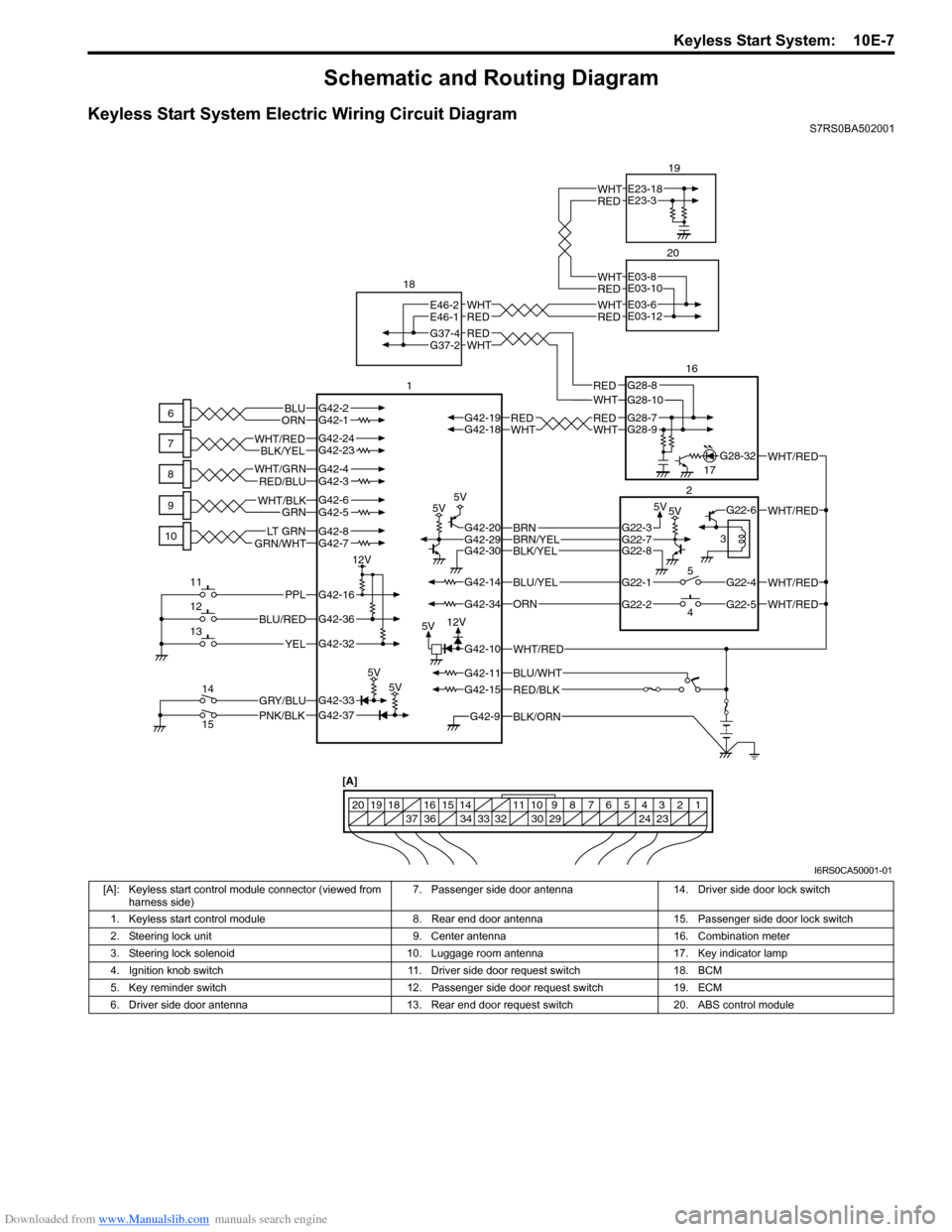
Keyless Start System Electric Wiring Circuit DiagramS7RS0BA502001
BLK/ORNG42-9
G42-15
G42-14
G42-37G42-33
G42-16
G42-20G42-29G42-30
G42-36
G42-32G42-10
G42-34
G42-11BLU/WHT
WHT/RED
WHT/RED
WHT/RED
PNK/BLKGRY/BLU
BLU/RED
YEL
PPL
RED/BLK
5V5V
5V5V
5V5V
5V
12V
12V
G42-2G42-1BLUORNWHTREDWHTREDG42-18G42-19G28-9G28-7
BLU/YEL
ORN
G42-24G42-23BLK/YELWHT/RED
G42-7GRN/WHTLT G R NG42-8
G42-5G42-6GRNWHT/BLK
G42-4G42-3WHT/GRNRED/BLU
BLK/YELBRN/YELBRNG22-3
G22-1
G22-2G22-5
G22-4
G22-6
G22-7G22-8
WHT/RED
WHT/RED
G37-4
REDWHTREDWHT
G28-10G28-8WHTRED
RED
WHT
G37-2
E46-2
E46-1E03-6
E03-12
G28-32
6
7
8
9
10
11
12
13
14
15 1
18
20
1617
2
4 5 3
1234567891011
141516
36 34 33 32 30 29 24 23
37
181920
[A]
REDWHTE23-18
E23-3
19
REDWHTE03-8
E03-10
I6RS0CA50001-01
[A]: Keyless start control module connector (viewed from
harness side) 7. Passenger side door antenna 14. Driver side door lock switch
1. Keyless start control module 8. Rear end door antenna 15. Passenger side door lock switch
2. Steering lock unit 9. Center antenna 16. Combination meter
3. Steering lock solenoid 10. Luggage room antenna 17. Key indicator lamp
4. Ignition knob switch 11. Driver side door request switch 18. BCM
5. Key reminder switch 12. Passenger side door request switch 19. ECM
6. Driver side door antenna 13. Rear end door request switch 20. ABS control module
Page 1474 of 1496
Downloaded from www.Manualslib.com manuals search engine 10E-12 Keyless Start System:
DTC ClearanceS7RS0BA504009
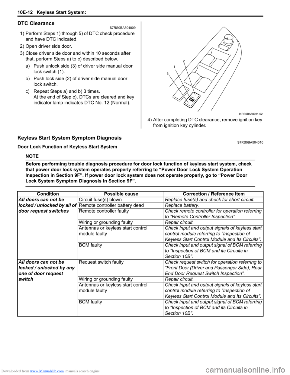
1) Perform Steps 1) through 5) of DTC check procedure and have DTC indicated.
2) Open driver side door.
3) Close driver side door and within 10 seconds after that, perform Steps a) to c) described below.
a) Push unlock side (3) of driver side manual door lock switch (1).
b) Push lock side (2) of driver side manual door lock switch.
c) Repeat Steps a) and b) 3 times. At the end of Step c), DTCs are cleared and key
indicator lamp indicates DTC No. 12 (Normal).
4) After completing DTC clearance, remove ignition key from ignition key cylinder.
Keyless Start System Symptom DiagnosisS7RS0BA504010
Door Lock Function of Keyless Start System
NOTE
Before performing trouble diagnosis procedure for door lock function of keyless start system, check
that power door lock system operates properly referring to “Power Door Lock System Operation
Inspection in Section 9F”. If power door lock system does not operate properly, go to “Power Door
Lock System Symptom Diagnosis in Section 9F”.
1
3 2
I4RS0BA50011-02
Condition
Possible cause Correction / Reference Item
All doors can not be
locked / unlocked by all of
door request switches Circuit fuse(s) blown
Replace fuse(s) and check for short circuit.
Remote controller battery dead Replace battery.
Remote controller faulty Check remote controller for operation referring
to “Remote Controller Inspection”.
Wiring or grounding faulty Repair circuit.
Antennas or keyless start control
module faulty Check input and output signals of keyless start
control module referring to “Inspection of
Keyless Start Control Mo
dule and Its Circuits”.
BCM faulty Check input and output signal of BCM referring
to “Inspection of BCM and its Circuits in
Section 10B”.
All doors can not be
locked / unlocked by any
one of door request
switch Request switch faulty
Check request switch for operation referring to
“Front Door (Driver and Passenger Side), Rear
End Door Request Switch Inspection”.
Wiring or grounding faulty Repair circuit.
Antennas or keyless start control
module faulty Check input and output signals of keyless start
control module referring to “Inspection of
Keyless Start Control Mo
dule and Its Circuits”.
BCM faulty Check input and output signal of BCM referring
to “Inspection of BCM and its Circuits in
Section 10B”.
Page 1475 of 1496
Downloaded from www.Manualslib.com manuals search engine Keyless Start System: 10E-13
Keyless Engine Start Function
NOTE
Before performing symptom diagnosis procedure for keyless engine start system, check that engine
starts by using ignition key. If it cannot be started by using ignition key, go to “Engine Symptom
Diagnosis in Section 1A”.
Keyless Start System Operation InspectionS7RS0BA504011
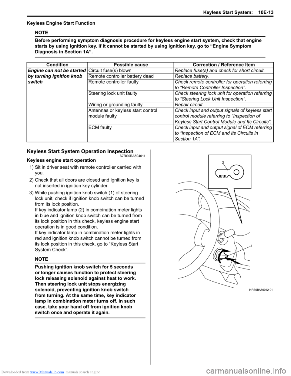
Keyless engine start operation
1) Sit in driver seat with re mote controller carried with
you.
2) Check that all doors are closed and ignition key is not inserted in ignition key cylinder.
3) While pushing ignition knob switch (1) of steering lock unit, check if ignition knob switch can be turned
from its lock position.
If key indicator lamp (2) in combination meter lights
in blue and ignition knob switch can be turned from
its lock position in this check, keyless engine start
operation is in good condition.
If key indicator lamp in combination meter lights in
red and ignition knob switch cannot be turned from
its lock position in this check, go to “Keyless Start
System Check”.
NOTE
Pushing ignition knob switch for 5 seconds
or longer causes function to protect steering
lock releasing solenoid against heat to work.
Then steering lock unit stops energizing
solenoid, preventing ignition knob switch
from turning. At the same time, key indicator
lamp in combination mete r turns off. In such
case, take your hand off from ignition knob
switch once and operate it again.
Condition Possible cause Correction / Reference Item
Engine can not be started
by turning Ignition knob
switch Circuit fuse(s) blown
Replace fuse(s) and check for short circuit.
Remote controller battery dead Replace battery.
Remote controller faulty Check remote controller for operation referring
to “Remote Controller Inspection”.
Steering lock unit faulty Check steering lock unit for operation referring
to “Steering Lock Unit Inspection”.
Wiring or grounding faulty Repair circuit.
Antennas or keyless start control
module faulty Check input and output signals of keyless start
control module referring to “Inspection of
Keyless Start Control Mo
dule and Its Circuits”.
ECM faulty Check input and output signal of ECM referring
to “Inspection of ECM and Its Circuits in
Section 1A”.
1
2
I4RS0BA50012-01
Page 1480 of 1496
Downloaded from www.Manualslib.com manuals search engine 10E-18 Keyless Start System:
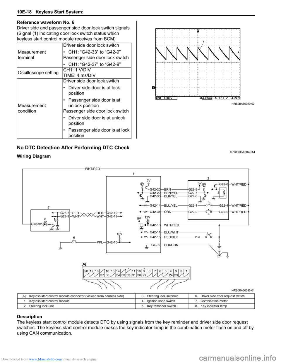
Reference waveform No. 6
Driver side and passenger side door lock switch signals
(Signal (1) indicating door lock switch status which
keyless start control module receives from BCM)
No DTC Detection After Performing DTC CheckS7RS0BA504014
Wiring Diagram
Description
The keyless start control module detect s DTC by using signals from the key reminder and driver side door request
switches. The keyless start control module makes the key indicator lamp in the combination meter flash on and off by
using CAN communication. Measurement
terminal
Driver side door lock switch
• CH1: “G42-33” to “G42-9”
Passenger side door lock switch
• CH1: “G42-37” to “G42-9”
Oscilloscope setting CH1: 1 V/DIV
TIME: 4 ms/DIV
Measurement
condition Driver side door lock switch
• Driver side door is at lock
position
• Passenger side door is at unlock position
Passenger side door lock switch
• Driver side door is at unlock position
• Passenger side door is at lock position
I4RS0BA50020-02
BLK/ORNG42-9
G42-15
G42-14
G42-16
G42-20G42-29G42-30
G42-10
G42-34
G42-11BLU/WHT
WHT/RED
WHT/RED
WHT/RED
PPL
RED/BLK
5V5V
5V5V
5V
12V
12VWHTREDWHTREDG42-18G42-19G28-9G28-7
BLU/YEL
ORN
BLK/YELBRN/YELBRNG22-3
G22-1
G22-2G22-5
G22-4
G22-6
G22-7G22-8
WHT/RED
WHT/RED
G28-32
6
7
8 1
2
4 5 3
1234567891011
141516
36 34 33 32 31 30 29 24 23
37
181920
[A]
I4RS0BA50035-01
[A]: Keyless start control module connector (viewed from harne
ss side) 3. Steering lock solenoid 6. Driver side door request switch
1. Keyless start control module 4. Ignition knob switch 7. Combination meter
2. Steering lock unit 5. Key reminder switch 8. Key indicator lamp
Page 1482 of 1496
Downloaded from www.Manualslib.com manuals search engine 10E-20 Keyless Start System:
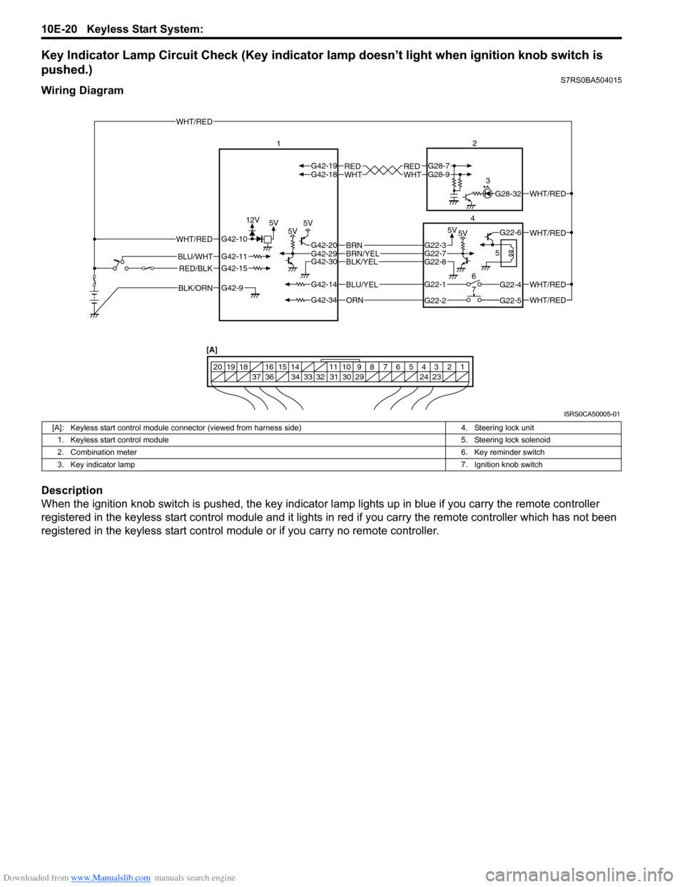
Key Indicator Lamp Circuit Check (Key indicator lamp doesn’t light when ignition knob switch is
pushed.)
S7RS0BA504015
Wiring Diagram
Description
When the ignition knob switch is pushed, the key indicator lamp lights up in blue if you carry the remote controller
registered in the keyless start control module and it lights in red if you carry the remote controller which has not been
registered in the keyless start control module or if you carry no remote controller.
G42-14
G42-20G42-29G42-30
G42-34
WHT/RED
WHT/RED
5V5V
5V5V
BLK/ORNG42-9
G42-15
G42-10
G42-11BLU/WHT
WHT/RED
WHT/RED
RED/BLK
5V
12V
WHTREDWHTREDG42-18G42-19G28-9G28-7
G28-32
BLU/YEL
ORN
BLK/YELBRN/YELBRNG22-3
G22-1
G22-2G22-5
G22-4
G22-6
G22-7G22-8
WHT/RED
WHT/RED
1234567891011
141516
36 34 33 32 31 30 29 24 23
37
181920
1
2
4 5
7 6
[A] 3
I5RS0CA50005-01
[A]: Keyless start control module connector (viewed from harness side)
4. Steering lock unit
1. Keyless start control module 5. Steering lock solenoid
2. Combination meter 6. Key reminder switch
3. Key indicator lamp 7. Ignition knob switch