2008 SUZUKI SWIFT G28
[x] Cancel search: G28Page 595 of 1496
Downloaded from www.Manualslib.com manuals search engine Electronic Stability Program: 4F-21
Stability control (ACTIVE, INACTIVE): This indicates
stability control in acti vation / deactivation.
TCS control (brake) ( ACTIVE, INACTIVE): This
indicates brake function of TCS in activation /
deactivation.
TCS control (engine) (ACTIVE, INACTIVE): This
indicates torque control of TCS in activation /
deactivation. ESP®
off state (cont) (ESP ® ON, ESP ® OFF): State
of ESP ® OFF switch.
Steering angle Sen (Neutral, NON newtral): This
indicates steering wheel angle measured by steering
angle sensor is in straight-ahead or not.
Visual InspectionS7RS0B4604059
Check the following parts and systems visually.
ESP ® Warning Lamp Does Not Come ON at Ignition Switch ONS7RS0B4604008
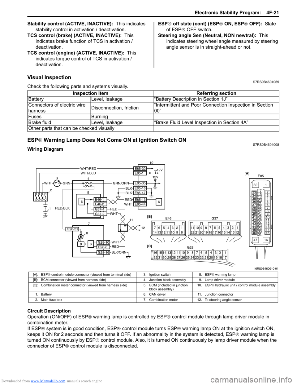
Wiring Diagram
Circuit Description
Operation (ON/OFF) of ESP ® warning lamp is controlled by ESP ® control module through lamp driver module in
combination meter.
If ESP ® system is in good condition, ESP ® control module turns ESP ® warning lamp ON at the ignition switch ON,
keeps it ON for 2 seconds and then turns it OFF. If an abnormality in the system is detected, ESP ® warning lamp is
turned ON continuously by ESP ® control module. Also, it is turned ON continuously by lamp driver module when the
connector of ESP ® control module is disconnected.Inspection Item Referring section
Battery Level, leakage “Battery Description in Section 1J”
Connectors of electric wire
harness Disconnection, friction“Intermittent and Poor Connec
tion Inspection in Section
00”
Fuses Burning
Brake fluid Level, leakage “Brake Fluid Level Inspection in Section 4A”
Other parts that can be checked visually
[A] E85
161
15
2
3
4
5
6
7
8
9
10
11
12
13
14
17
18
19
20
21
22
23
24
25
26
27
28
29
30
31
3233
34
35
36
37
38
39
40
41
42
43
44
45
46
47
WHTGRN
3
E85-13
E85-44REDWHT6 5E46-1E46-2
4 10
6
E85-16
E85-47BLKBLK
8
9
BLK/ORN
REDWHT
REDWHT
G37-4G37-2
G28-10G28-8
G28-16
12V
12VE85-32E85-1
E85-35
WHT/REDWHT/BLU
GRN/ORN
6
2
1
7 1112[B]
G37
E46124
53
67
891011121314124
53
67
891011
1213141516171819202122
[C] G28
12345678910111213141516
17181920212223242526272829303132
G28-31
RED/BLK
I6RS0B460010-01
[A]: ESP ® control module connector (viewed from terminal side) 3. Ignition switch 8. ESP ® warning lamp
[B]: BCM connector (viewed from harness side) 4. Junction block assembly 9. Lamp driver module
[C]: Combination meter connector (viewed from harness side) 5. BCM (included in junction
block assembly) 10. ESP
® hydraulic unit / control module assembly
1. Battery 6. CAN driver 11. Junction connector
2. Main fuse box 7. Combination meter 12. To steering angle sensor
Page 596 of 1496
Downloaded from www.Manualslib.com manuals search engine 4F-22 Electronic Stability Program:
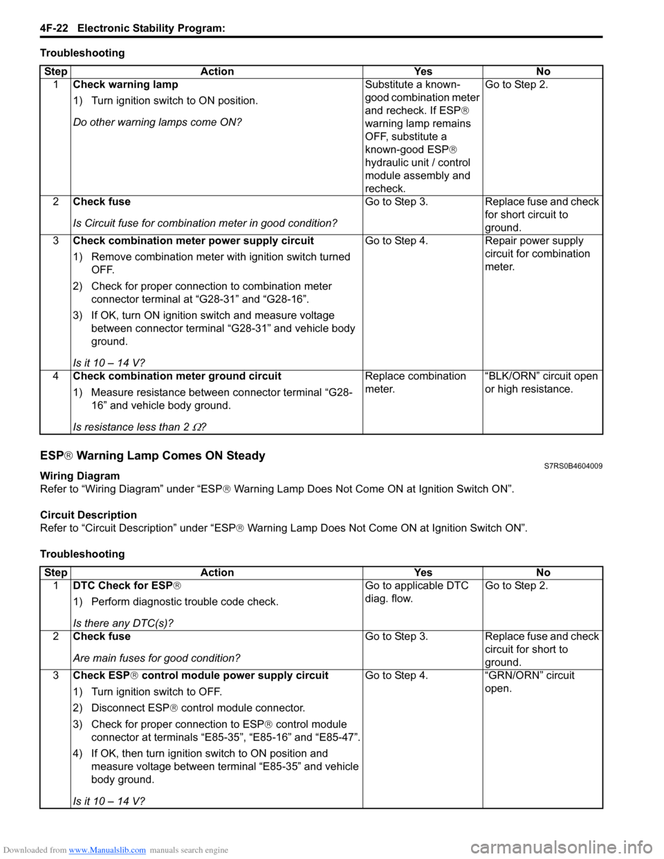
Troubleshooting
ESP® Warning Lamp Comes ON SteadyS7RS0B4604009
Wiring Diagram
Refer to “Wiring Diagram” under “ESP ® Warning Lamp Does Not Come ON at Ignition Switch ON”.
Circuit Description
Refer to “Circuit Description” under “ESP ® Warning Lamp Does Not Come ON at Ignition Switch ON”.
Troubleshooting Step Action Yes No
1 Check warning lamp
1) Turn ignition switch to ON position.
Do other warning lamps come ON? Substitute a known-
good combination meter
and recheck. If ESP®
warning lamp remains
OFF, substitute a
known-good ESP ®
hydraulic unit / control
module assembly and
recheck. Go to Step 2.
2 Check fuse
Is Circuit fuse fo r combination meter in good condition? Go to Step 3. Replace fuse and check
for short circuit to
ground.
3 Check combination meter power supply circuit
1) Remove combination meter wit h ignition switch turned
OFF.
2) Check for proper connection to combination meter connector terminal at “G28-31” and “G28-16”.
3) If OK, turn ON ignition switch and measure voltage between connector terminal “G28-31” and vehicle body
ground.
Is it 10 – 14 V? Go to Step 4. Repair power supply
circuit for combination
meter.
4 Check combination me ter ground circuit
1) Measure resistance between connector terminal “G28- 16” and vehicle body ground.
Is resistance less than 2
Ω? Replace combination
meter.
“BLK/ORN” circuit open
or high resistance.
Step
Action YesNo
1 DTC Check for ESP ®
1) Perform diagnostic trouble code check.
Is there any DTC(s)? Go to applicable DTC
diag. flow.
Go to Step 2.
2 Check fuse
Are main fuses for good condition? Go to Step 3.
Replace fuse and check
circuit for short to
ground.
3 Check ESP ® control module power supply circuit
1) Turn ignition switch to OFF.
2) Disconnect ESP ® control module connector.
3) Check for proper connection to ESP ® control module
connector at terminals “E85-35”, “E85-16” and “E85-47”.
4) If OK, then turn ignition switch to ON position and measure voltage between terminal “E85-35” and vehicle
body ground.
Is it 10 – 14 V? Go to Step 4.
“GRN/ORN” circuit
open.
Page 597 of 1496
Downloaded from www.Manualslib.com manuals search engine Electronic Stability Program: 4F-23
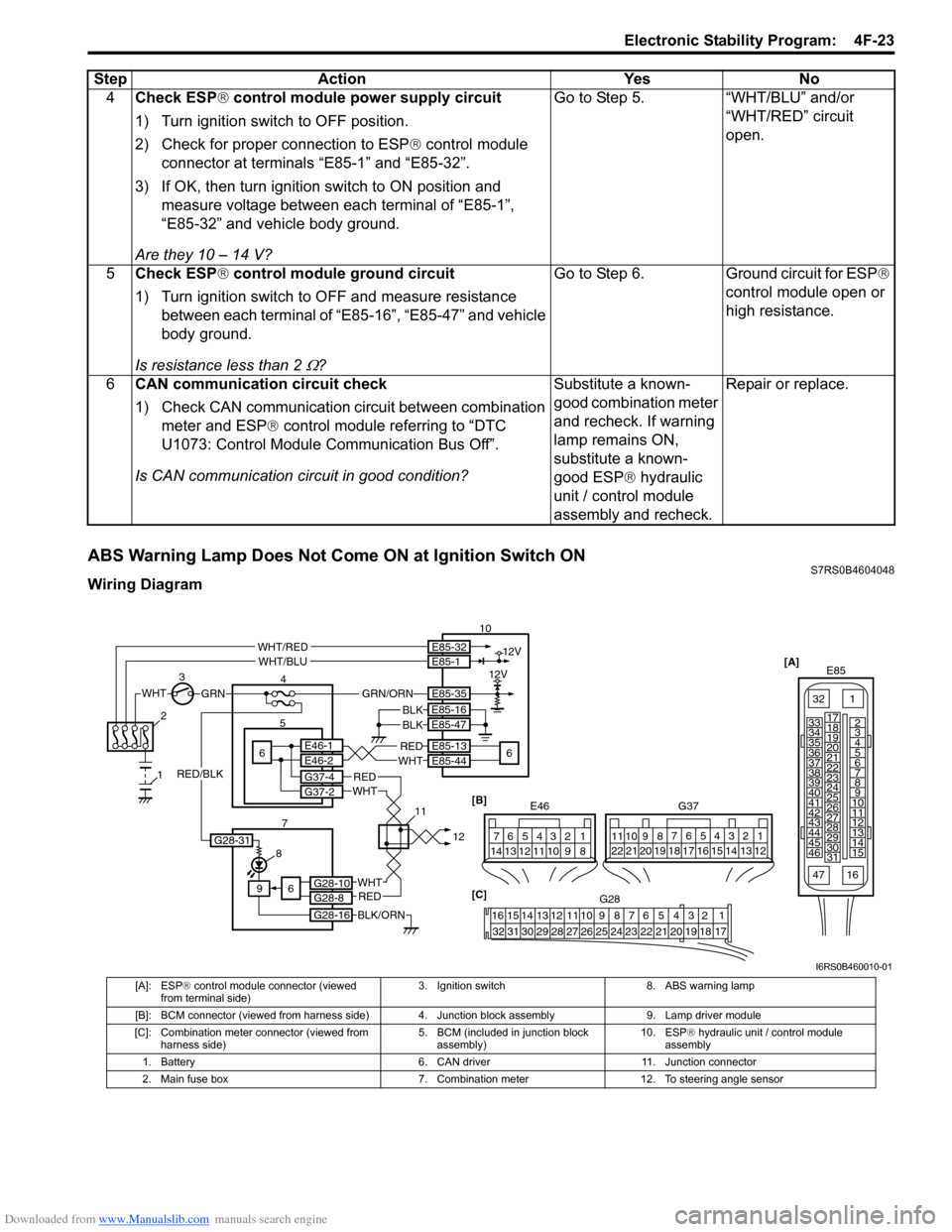
ABS Warning Lamp Does Not Come ON at Ignition Switch ONS7RS0B4604048
Wiring Diagram4
Check ESP ® control module power supply circuit
1) Turn ignition switch to OFF position.
2) Check for proper connection to ESP ® control module
connector at terminals “E85-1” and “E85-32”.
3) If OK, then turn ignition switch to ON position and measure voltage between each terminal of “E85-1”,
“E85-32” and vehicle body ground.
Are they 10 – 14 V? Go to Step 5. “WHT/BLU” and/or
“WHT/RED” circuit
open.
5 Check ESP ® control module ground circuit
1) Turn ignition switch to OFF and measure resistance between each terminal of “E85-16”, “E85-47” and vehicle
body ground.
Is resistance less than 2
Ω? Go to Step 6.
Ground circuit for ESP®
control module open or
high resistance.
6 CAN communication circuit check
1) Check CAN communication circuit between combination
meter and ESP ® control module referring to “DTC
U1073: Control Module Communication Bus Off”.
Is CAN communication circuit in good condition? Substitute a known-
good combination meter
and recheck. If warning
lamp remains ON,
substitute a known-
good ESP
® hydraulic
unit / control module
assembly and recheck. Repair or replace.
Step
Action YesNo
[A]
E85
161
15
2
3
4
5
6
7
8
9
10
11
12
13
14
17
18
19
20
21
22
23
24
25
26
27
28
29
30
31
3233
34
35
36
37
38
39
40
41
42
43
44
45
46
47
WHTGRN
3
E85-13
E85-44REDWHT6 5E46-1E46-2
4 10
6
E85-16
E85-47BLKBLK
8
9
BLK/ORN
REDWHT
REDWHT
G37-4G37-2
G28-10G28-8
G28-16
12V
12VE85-32E85-1
E85-35
WHT/REDWHT/BLU
GRN/ORN
6
2
1
7 1112[B]
G37
E46124
53
67
891011121314124
53
67
891011
1213141516171819202122
[C] G28
12345678910111213141516
17181920212223242526272829303132
G28-31
RED/BLK
I6RS0B460010-01
[A]: ESP ® control module connector (viewed
from terminal side) 3. Ignition switch 8. ABS warning lamp
[B]: BCM connector (viewed from harness side) 4. Junction block assembly 9. Lamp driver module
[C]: Combination meter connector (viewed from harness side) 5. BCM (included in junction block
assembly) 10. ESP
® hydraulic unit / control module
assembly
1. Battery 6. CAN driver11. Junction connector
2. Main fuse box 7. Combination meter12. To steering angle sensor
Page 598 of 1496
Downloaded from www.Manualslib.com manuals search engine 4F-24 Electronic Stability Program:
Circuit Description
Operation (ON/OFF) of ABS warning lamp is controlled by ESP® control module through lamp driver module in
combination meter.
If antilock brake system is in good condition, ESP ® control module turns ABS warning lamp ON at the ignition switch
ON, keeps it ON for 2 seconds and then turns it OFF. If an abnormality in the system is detected, ABS warning lamp is
turned ON continuously by ESP ® control module. Also, it is turned ON continuously by lamp driver module when the
connector of ESP ® control module is disconnected.
Troubleshooting
Refer to “Troubleshooting” under “ESP ® Warning Lamp Does Not Come ON at Ignition Switch ON”.
ABS Warning Lamp Comes ON SteadyS7RS0B4604049
Wiring Diagram
Refer to “Wiring Diagram” under “ABS Warning Lamp Does Not Come ON at Ignition Switch ON”.
Circuit Description
Refer to “Circuit Description” u nder “ABS Warning Lamp Does Not Co me ON at Ignition Switch ON”.
Troubleshooting
Refer to “Troubleshooting” under “ESP ® Warning Lamp Comes ON Steady”.
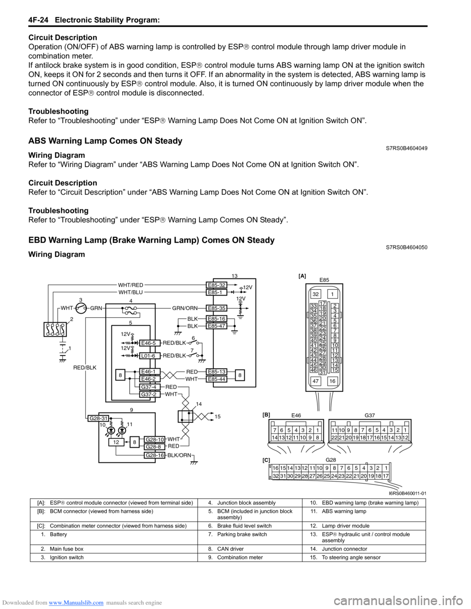
EBD Warning Lamp (Brake Warning Lamp) Comes ON SteadyS7RS0B4604050
Wiring Diagram
[A]
E85
161
15
2
3
4
5
6
7
8
9
10
11
12
13
14
17
18
19
20
21
22
23
24
25
26
27
28
29
30
31
3233
34
35
36
37
38
39
40
41
42
43
44
45
46
47WHTGRN
3
E85-13
E85-44REDWHT8 5E46-1E46-2
4
13
8
E85-16
E85-47BLKBLK
1110
12
BLK/ORN
REDWHT
REDWHT
G37-4G37-2
G28-10G28-8
G28-16
12V
12VE85-32E85-1
E85-35
WHT/REDWHT/BLU
GRN/ORN
8
2
1
9 1415
[B]
G37
E46
124
53
67
891011121314124
53
67
891011
1213141516171819202122
[C] G28
12345678910111213141516
17181920212223242526272829303132
12V
12V
6
7E46-5
L01-6
RED/BLK
RED/BLK
G28-31
RED/BLK
I6RS0B460011-01
[A]: ESP ® control module connector (viewed from terminal side) 4. Junction block assembly 10. EBD warning lamp (brake warning lamp)
[B]: BCM connector (viewed from harness side) 5. BCM (included in junction block
assembly) 11. ABS warning lamp
[C]: Combination meter connector (viewed from harness side) 6. Brake fluid level switch 12. Lamp driver module 1. Battery 7. Parking brake switch 13. ESP ® hydraulic unit / control module
assembly
2. Main fuse box 8. CAN driver 14. Junction connector
3. Ignition switch 9. Combination meter 15. To steering angle sensor
Page 600 of 1496
![SUZUKI SWIFT 2008 2.G Service Workshop Manual Downloaded from www.Manualslib.com manuals search engine 4F-26 Electronic Stability Program:
Serial Data Link Circuit CheckS7RS0B4604012
Wiring Diagram
Inspection
[A]E85
161
15
2
3
4
5
6
7
8
9
10
11
SUZUKI SWIFT 2008 2.G Service Workshop Manual Downloaded from www.Manualslib.com manuals search engine 4F-26 Electronic Stability Program:
Serial Data Link Circuit CheckS7RS0B4604012
Wiring Diagram
Inspection
[A]E85
161
15
2
3
4
5
6
7
8
9
10
11](/manual-img/20/7607/w960_7607-599.png)
Downloaded from www.Manualslib.com manuals search engine 4F-26 Electronic Stability Program:
Serial Data Link Circuit CheckS7RS0B4604012
Wiring Diagram
Inspection
[A]E85
161
15
2
3
4
5
6
7
8
9
10
11
12
13
14
17
18
19
20
21
22
23
24
25
26
27
28
29
30
31
3233
34
35
36
37
38
39
40
41
42
43
44
45
46
47WHTGRN
3
E85-13REDWHT6 5E46-1E46-2
4
10
6
E85-16
E85-47BLKBLK
8
9
BLK/ORN
REDWHT
REDWHT
G37-4G37-2
G28-10G28-8
G28-16
G28-31
12V
12VE85-32E85-1
E85-35
WHT/REDWHT/BLU
GRN/ORN
6
2
1
7 1415 [B]
G37
E46
124
53
67
891011121314124
53
67
891011
1213141516171819202122
[C] G28
12345678910111213141516
17181920212223242526272829303132
12V
11
PPL/WHT
PPL/WHT
E85-33
E85-44
12
13
WHTWHT/REDB
G G1
RED/BLK
I6RS0B460012-01
[A]: ESP
® control module connector (viewed
from terminal side) 4. Junction block assembly 10. ESP
® hydraulic unit / control module assembly
[B]: BCM connector (viewed from harness side) 5. BCM (included in junction block
assembly) 11. Data link connector (DLC)
[C]: Combination meter connector (viewed from harness side) 6. CAN driver 12. To SDM
1. Battery 7. Combination meter 13. To ECM and P/S control module
2. Main fuse box 8. ESP ® warning lamp 14. Junction connector
3. Ignition switch 9. Lamp driver module 15. To steering angle sensor
Step Action YesNo
1 Check ESP ® warning lamp
1) Turn ignition switch to ON position.
Does ESP
® warning lamp come ON? Go to Step 2. Go to Step 6.
2 Check fuse
1) Turn ignition switch to OFF position.
Are main fuses for good condition? Go to Step 3. Replace fuse and check
for short.
3 Check ESP ® control module power supply circuit
1) Disconnect ESP ® control module connector.
2) Check for proper connection to ESP ® control module
connector at terminal “E85-35”.
3) If OK, then turn ignition switch to ON position and measure voltage between terminal “E85-35” and vehicle
body ground.
Is it 10 – 14 V? Go to Step 4.
“GRN/ORN” wire circuit
open.
Page 623 of 1496

Downloaded from www.Manualslib.com manuals search engine Electronic Stability Program: 4F-49
DTC U1073: Control Module Communication Bus OffS7RS0B4604057
Wiring Diagram
DTC Detecting Condition and Trouble Area
E85-13E85-44
E46-2E46-1
G37-4G37-2
E85-46E85-42
E23-3E23-18
G50-9G50-10
G28-8G28-10
G28-9G28-7
G42-19G42-18
REDWHT
WHTRED
WHTRED
REDWHT
REDWHT
WHTRED
REDWHT
REDWHT
REDWHT
[A]
21
E2334
1819
5671011
17
20
47 46
495051
2122
52 16
25 9
24
14
29
5557 54 53
59
60 5826
27
28
15
30
56 4832 31343536374042 39 38
44
45 43 41 33
1213
238
G42[F]
1234567891011
141516
36 34 33 32 31 30 29 24 23
37
181920
[B]
E85
161
15
2
3
4
5
6
7
8
9
10
11
12
13
14
17
18
19
20
21
22
23
24
25
26
27
28
29
30
31
3233
34
35
36
37
38
39
40
41
42
43
44
45
46
47 [C]
G37
E46
124
53
67
891011121314124
53
67
891011
1213141516171819202122
[E] G28
12345678910111213141516
17181920212223242526272829303132
[D] G50
109 321
4
5
7 1
2
3
6
I7RS0B460011-02
[A]: ECM connector (viewed from harness side) [F]: Keyless start control module
connector (viewed from
harness side) 5. Combination meter
[B]: ESP ® control module connector (viewed from
terminal side) 1. ECM
6. Keyless start control module (if equipped)
[C]: BCM connector (viewed from harness side) 2. ESP® hydraulic unit / control
module assembly 7. Junction connector
[D]: Steering angle sensor connector (viewed from harness side) 3. BCM
[E]: Combination meter connector (viewed from harness side) 4. Steering angle sensor
DTC Detecting Condition
Trouble Area
Transmission error that is inconsistent between
transmission data and transmission monitor (CAN bus
monitor) data is detected more than 7 times continuously. • CAN communication circuit
•ECM
• ESP
® control module
•BCM
• Steering angle sensor
• Combination meter
• Keyless start control module (if equipped)
Page 715 of 1496
Downloaded from www.Manualslib.com manuals search engine Automatic Transmission/Transaxle: 5A-71
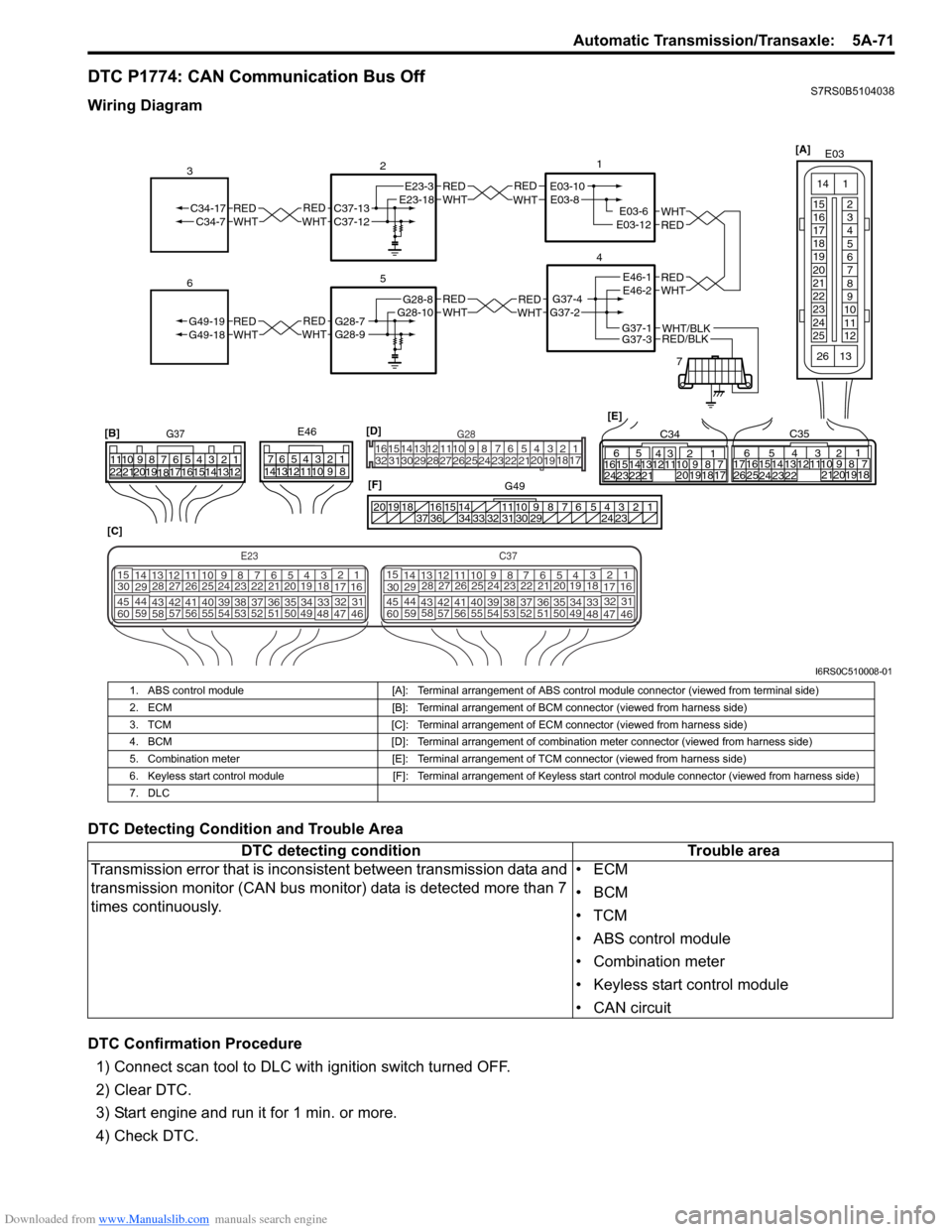
DTC P1774: CAN Communication Bus OffS7RS0B5104038
Wiring Diagram
DTC Detecting Condition and Trouble Area
DTC Confirmation Procedure1) Connect scan tool to DLC with ignition switch turned OFF.
2) Clear DTC.
3) Start engine and run it for 1 min. or more.
4) Check DTC.
REDWHTE03-6E03-12
1
4
7
REDWHT
2
[C]
[B]
G37E46
1234567
1234567
891011
891011
121314 121314
151617
18
19202122 [E]65
1615 14131211 43
2423 2122 10 9 8 7
21
1920 1817
C3417 16
26 2515 14
65 3
42
13 12
23 2224 1110 9
212019 87
18
1
C35
[F]
REDWHTC37-13C37-12REDWHTC34-17C34-7
3
1234567891011
141516
36 34 33 32 31 30 29 24 23
37
181920
[D] [A]
G49
E23-3E23-18
5
REDWHTG28-7G28-9REDWHTG49-19G49-18
6
REDWHTE03-10E03-8
G37-4G37-2
REDWHTE46-1E46-2REDWHTREDWHTG28-8G28-10
RED/BLKWHT/BLKG37-3G37-1
E03
15
16
17
18
19
20
21
22
23
24
25 2
3
4
5
6
7
8
9
10
11
12
1
13
14
26
E23C37
34
1819
567
1011
17
20
47 46
495051
2122
52 16
25 9
24
14
29
5557 54 53
59
60 58 2
262728
15
30
56 4832 31
34353637
4042 39 38
44
45 43 41 33 1
1213
238
34
1819
567
1011
17
20
47 46
495051
2122
52 16
25 9
24
14
29
5557 54 53
59
60 58 2
262728
15
30
56 4832 31
34353637
4042 39 38
44
45 43 41 331
1213
238
G281234567
8
910111213141516
1718
19
20
212223242526272829303132
I6RS0C510008-01
1. ABS control module [A]: Terminal arrangement of ABS control module connector (viewed from terminal side)
2. ECM [B]: Terminal arrangement of BCM connector (viewed from harness side)
3. TCM [C]: Terminal arrangement of ECM connector (viewed from harness side)
4. BCM [D]: Terminal arrangement of combination meter connector (viewed from harness side)
5. Combination meter [E]: Terminal arrangement of TCM connector (viewed from harness side)
6. Keyless start control module [F]: Terminal arrangement of Keyless start control module connector (viewed from harness side)
7. DLC
DTC detecting condition Trouble area
Transmission error that is incons istent between transmission data and
transmission monitor (CAN bus monitor) data is detected more than 7
times continuously. •ECM
•BCM
•TCM
• ABS control module
• Combination meter
• Keyless start control module
• CAN circuit
Page 886 of 1496

Downloaded from www.Manualslib.com manuals search engine 6C-4 Power Assisted Steering System:
Schematic and Routing Diagram
EPS System Wiring Circuit DiagramS7RS0B6302001
M
5V
BRNRED/
BLU
BLK
RED
WHT
BLU
GRN
BRN YEL
E52-11
E52-14E52-12
E23-4
E23-26
E23-25 E51-1
E51-2
E52-18
E53-5
E53-7
E52-6
E52-8
E53-2
E52-9
E52-16
E52-19
GRY
PPL/WHT
[A ]
[E ]
12 3
4 5 67
89
11
10
12 13
141516
17 18 19 20
1
2
[B ][C ]
1210 9 8 7654 3 21
16 15 14 13 12 11
26 25 24 2322 21 20 19 18 17
32 31 30 29 28 27
[D]
5V
PPL
E52-4
11
12
13 14
15
10
9
16
12V
5V
5V
12V
REDE52-20E53-6
E53-4
E53-1
7654321
5
REDRED/
BLKWHT
6WHTWHT/BLKWHTBLK
12V
12V
17BLK
GRY
LT GRN
/BLK
E52-1
E52-5
E49-1
GRNGRNWHTBLK
WHY
G28-25G28-31
RED/BLK
18
3
4
4
7 8
4
4
1 2
4
E49-2BLK
I7RS0B630002-01
[A]: Connector “E52” (viewed from harness side) 4. Fuse 12. P/S motor
[B]: Connector “E49” (viewed from harness side ) 5. Left-front wheel speed sensor 13. Shield
[C]: Connector “E51” (viewed from harness side) 6 . Right-front wheel speed sensor 14. Torque sensor
[D]: Connector “G28” (viewed from harness side) 7. Combination meter 15. Torque sensor amplifier
[E]: Connector “E53” (viewed from harness side) 8. “EPS” warning light16. To ECM, BCM, Air bag SDM and ABS control module assembly
1. Main fuse box 9. Date link connector (DLC) 17. ABS/ESP ® control module
2. Ignition switch 10. ECM18. Individual circuit fuse box No.1
3. Junction block assembly 11. P/S control module