2008 SUZUKI SWIFT 1a 168
[x] Cancel search: 1a 168Page 621 of 1496

Downloaded from www.Manualslib.com manuals search engine Electronic Stability Program: 4F-47
DTC Troubleshooting
DTC C1090: Invalid Communication with ECMS7RS0B4604040
DTC Detecting Condition and Trouble Area
DTC TroubleshootingStep Action Yes No
1 Was “Electronic Stability Pr ogram Check” performed? Go to Step 2. Go to “Electronic
Stability Program
System Check”.
2 DTC check for ESP®
1) Connect scan tool to DLC with ignition switch turned
OFF.
2) Turn ignition switch ON and check DTC for ESP ®.
Is there any DTC(s) other than C1075, C1076 and C1078? Go to applicable DTC
diag. flow.
Go to Step 3.
3 Check sensor calibration
1) Calibrate all sens ors referring to “Sensor Calibration”.
2) Clear all DTC(s) and check DTC for ESP ®.
Is DTC C1075, C1076 and/ or C1078 still detected? DTC C1075: Substitute
a known-good steering
angle sensor and
recheck.
DTC C1076: Substitute
a known-good ESP
®
hydraulic unit / control
module assembly and
recheck.
DTC C1078: Substitute
a known-good yaw rate
/ G sensor assembly
and recheck. Calibration was
incompleted.
DTC Detecting Condition
Trouble Area
ESP ® control module rolling counte r failure is detected by
ECM. • CAN communication circuit
•ECM
• ESP
® control module
Step Action YesNo
1 Was “Electronic Stability Pr ogram Check” performed? Go to Step 2.Go to “Electronic
Stability Program
System Check”.
2 DTC check for ESP®
1) Connect scan tool to DLC with ignition switch turned
OFF.
2) Turn ignition switch ON and check DTC for ESP ®.
Is there any DTC(s) other than C1038 and C1090? Go to applicable DTC
diag. flow.
Go to Step 3.
3 DTC check for ECM
1) Check DTC for ECM.
Is DTC P1674 and/or DTC P1685 detected? Go to applicable DTC
diag. flow.
Substitute a known-
good ESP
® hydraulic
unit / control module
assembly and recheck.
Page 642 of 1496

Downloaded from www.Manualslib.com manuals search engine 5-ii Table of Contents
DTC P1878: Torque Converter Clutch Shudder .......................................................... 5A-75
DTC P2762: Torque Converter Clutch (TCC) Pressure Control Sole noid Control Circuit
Range /Performance ....................................... 5A-76
DTC P2763: Torque Converter Clutch Pressure Control Sole noid Control Circuit
High ................................................................. 5A-78
DTC P2764: Torque Converter Clutch Circuit Pressure Control Sole noid Control Circuit
Low ................................................................. 5A-80
Inspection of TCM and Its Circuits .................... 5A-82
TCM Power and Ground Circuit Check ............. 5A-86
Brake Interlock System Inspection .................... 5A-87
Repair Instructions ........... .................................5A-88
Learning Control Initializat ion ............................ 5A-88
A/T Fluid Level Check ....................................... 5A-89
A/T Fluid Change .............................................. 5A-90
Select Lever Components ... .............................. 5A-90
Select Lever Assembly Removal and Installation ....................................................... 5A-90
Select Lever Knob Installa tion........................... 5A-90
Select Lever Inspection .... ................................. 5A-91
“3” Position Switch Inspec tion ........................... 5A-91
Shift Lock Solenoid Inspec tion .......................... 5A-91
Shift Lock Solenoid Replacement ..................... 5A-91
Select Cable Components ................................ 5A-92
Select Cable Removal and Installation ............. 5A-92
Select Cable Adjustment ................................... 5A-93
Key Interlock Cable Removal and Installation... 5A-93
Transmission Range Sensor (Shift Switch) Inspection and Adjustment .............................. 5A-95
Output Shaft Speed Sensor Removal and Installation ....................................................... 5A-96
Output Shaft Speed Sensor Inspection ............. 5A-96
Input Shaft Speed Sensor Removal and Installation ....................................................... 5A-96
Input Shaft Speed Sensor Inspection................ 5A-97
Transmission Fluid Temperature Sensor Removal and Installation ................................. 5A-97
Transmission Fluid Temperature Sensor Inspection ........................................................ 5A-98
Solenoid Valves (Shift Solenoid Valves and Timing Solenoid Valve) Removal and
Installation ....................................................... 5A-98
Solenoid Valves (Shift Solenoid Valves, and Timing Solenoid Valve) Inspection .................. 5A-99
Pressure Control Soleno id Valves (Pressure
Control Solenoid and TCC Pressure Control
Solenoid) Removal and Inst allation .............. 5A-101
Pressure Control Solenoid Valve Inspection ... 5A-101
Transmission Control Module (TCM) Removal and Installation ............................... 5A-102
A/T Relay Inspection ....................................... 5A-103
Differential Side Oil Seal Replacement ........... 5A-103
A/T Fluid Cooler Hoses Replacement ............. 5A-104
Automatic Transaxle Unit Components........... 5A-105
Automatic Transaxle Unit Dismounting and Remounting ................................................... 5A-106
Automatic Transaxle Asse mbly Components . 5A-108 Automatic Transaxle Unit
Disassembly........... 5A-110
Oil Pump Assembly Components ................... 5A-121
Oil Pump Assembly Disassembly and Reassembly .................................................. 5A-122
Oil Pump Assembly Inspection ....................... 5A-122
Direct Clutch Assembly Components.............. 5A-124
Direct Clutch Assembly Preliminary Check ..... 5A-124
Direct Clutch Assembly Disassembly and Reassembly .................................................. 5A-125
Direct Clutch Assembly Inspection.................. 5A-127
Forward and Reverse Clutch Assembly Components .................................................. 5A-128
Forward and Reverse Clutch Assembly Preliminary Check ......................................... 5A-129
Forward and Reverse Clutch Assembly Disassembly and Reassembly ...................... 5A-129
Forward and Reverse Clutch Assembly Inspection ...................................................... 5A-133
2nd Brake Piston Assembly Components ....... 5A-134
2nd Brake Piston Assembly Disassembly and Reassembly .................................................. 5A-134
Transaxle Rear Cover (O/D and 2nd Coast Brake Piston) Assembly Components........... 5A-135
Transaxle Rear Cover (O/D and 2nd Coast Brake Piston) Assembly Disassembly and
Reassembly .................................................. 5A-136
Transaxle Rear Cover (O/D and 2nd Coast Brake Piston) Assembly Inspection............... 5A-137
Countershaft Assembly Co mponents.............. 5A-138
Countershaft Assembly Disassembly and Reassembly .................................................. 5A-138
Valve Body Assembly Components ................ 5A-139
Valve Body Assembly Disassembly and Reassembly .................................................. 5A-140
Differential Assembly Components ................. 5A-141
Differential Assembly Disassembly and Reassembly .................................................. 5A-142
Differential Assembly Inspection ..................... 5A-143
Torque Converter Housing Disassembly and Reassembly .................................................. 5A-144
Transaxle Case Disassembly and Reassembly .................................................. 5A-146
Automatic Transaxle Unit Inspection and Adjus
tment .................................................... 5A-147
Automatic Transaxle Unit Assembly ............... 5A-150
Specifications .................. .................................5A-167
Tightening Torque Specifications .................... 5A-167
Special Tools and Equipmen t .........................5A-168
Recommended Service Material ..................... 5A-168
Special Tool .................................................... 5A-168
Manual Transmission/Tr ansaxle ............ 5B-1
General Description .............................................5B-1
Manual Transaxle Construction and Servicing .... 5B-1
Diagnostic Information and Procedures ............5B-3 Manual Transaxle Symptom Diagnosis............... 5B-3
Repair Instructions ............ ..................................5B-3
Manual Transaxle Oil Change............................. 5B-3
Differential Side Oil Seal Replacement ............... 5B-4
Page 770 of 1496

Downloaded from www.Manualslib.com manuals search engine 5A-126 Automatic Transmission/Transaxle:
Reassembly
Reverse disassembly procedure for assembly, noting the
following points.
• Use new seal ring and O-ring. Apply A/T fluid before installation.
• Do not damage direct clutch return spring subassembly (1) and piston by pressing in direct
clutch return spring subassembly passing through its
original installing position over 0.7 mm (0.027 in.).
Special tool
(A): 09926–98310
• Apply A/T fluid to direct cl utch separator plates (4),
discs (3) and retaining plate (2).
• Install direct clutch separator plates (4), discs (3), retaining plate (2) and snap ring (1) to input shaft
subassembly.
• Install plate snap ring so that its both ends would be positioned in correct locations as shown in figure. • After assembly, measure direct clutch piston stroke.
Special tool
(A): 09900–20607
(B): 09900–20701
Direct clutch piston stroke
0.4 – 0.7 mm (0.016 – 0.027 in.)
When piston stroke is out of specification, select direct
clutch retaining plate with suitable thickness from
among the following table and replace it.
Available direct clutch retaining plate thickness
I2RH0B510168-01
I2RH0B510169-01
[A]: Correct [B]: Incorrect
ThicknessIdentification mark
3.0 mm (0.118 in.) 1
3.2 mm (0.126 in.) 2
3.4 mm (0.134 in.) 3
2.8 mm (0.110 in.) 4
1. Direct clutch assembly 3. Oil hole
2. Oil pump assembly
I2RH0B510170-01
I2RH0B510171-01
Page 812 of 1496
Downloaded from www.Manualslib.com manuals search engine 5A-168 Automatic Transmission/Transaxle:
Special Tools and Equipment
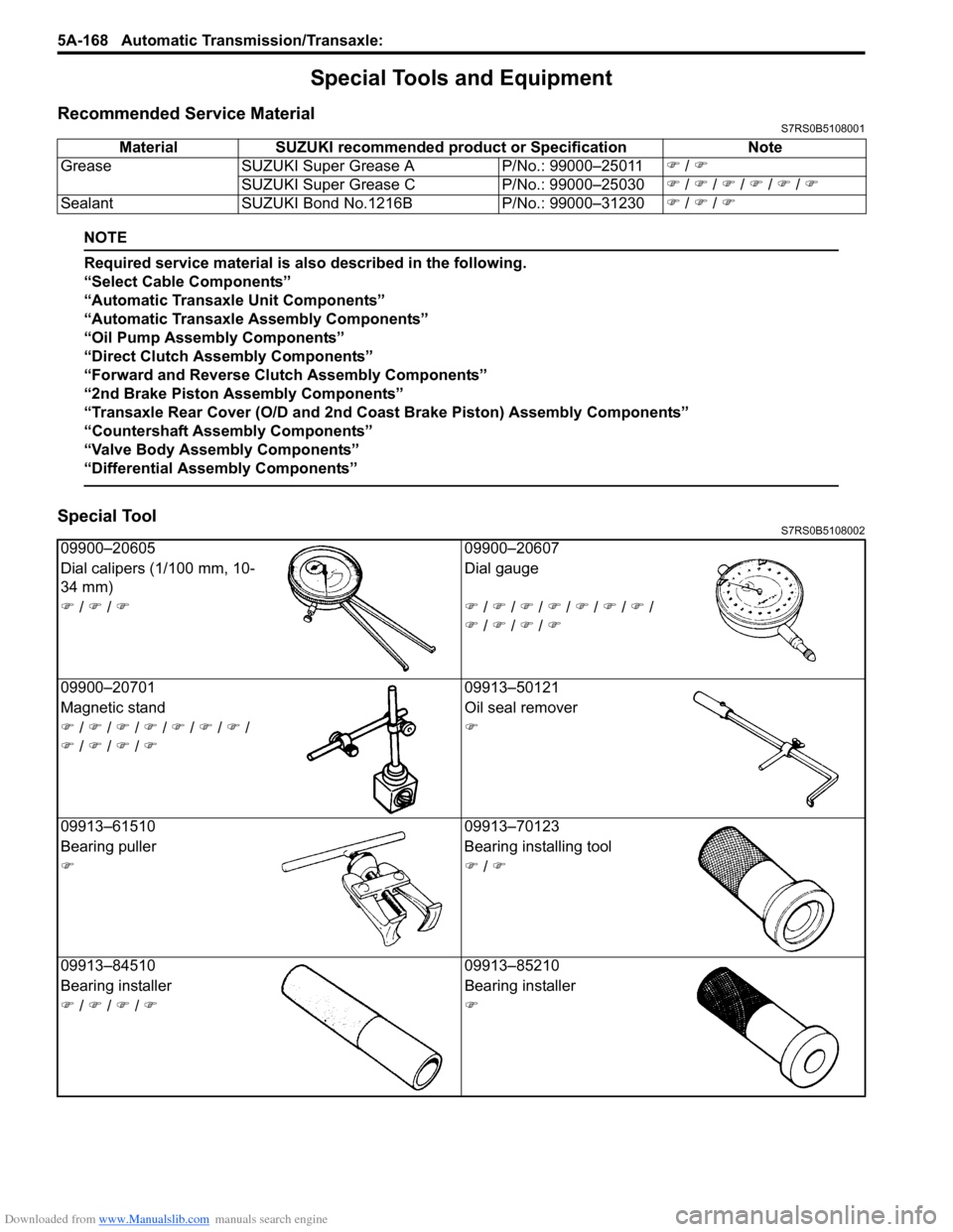
Recommended Service MaterialS7RS0B5108001
NOTE
Required service material is also described in the following.
“Select Cable Components”
“Automatic Transaxle Unit Components”
“Automatic Transaxle Assembly Components”
“Oil Pump Assembly Components”
“Direct Clutch Assembly Components”
“Forward and Reverse Clutch Assembly Components”
“2nd Brake Piston Assembly Components”
“Transaxle Rear Cover (O/D and 2nd Coast Brake Piston) Assembly Components”
“Countershaft Assembly Components”
“Valve Body Assembly Components”
“Differential Assembly Components”
Special ToolS7RS0B5108002
Material SUZUKI recommended product or Specification Note
Grease SUZUKI Super Grease A P/No.: 99000–25011�) / �)
SUZUKI Super Grease C P/No.: 99000–25030�) / �) / �) / �) / �) / �)
Sealant SUZUKI Bond No.1216B P/No.: 99000–31230�) / �) / �)
09900–20605 09900–20607
Dial calipers (1/100 mm, 10-
34 mm) Dial gauge
�) / �) / �)�) / �) / �) / �) / �) / �) / �) /
�) / �) / �) / �)
09900–20701 09913–50121
Magnetic stand Oil seal remover
�) / �) / �) / �) / �) / �) / �) /
�) / �) / �) / �) �)
09913–61510 09913–70123
Bearing puller Bearing installing tool
�)�) / �)
09913–84510 09913–85210
Bearing installer Bearing installer
�) / �) / �) / �)�)
Page 1450 of 1496
Downloaded from www.Manualslib.com manuals search engine 10C-7 Immobilizer Control System:
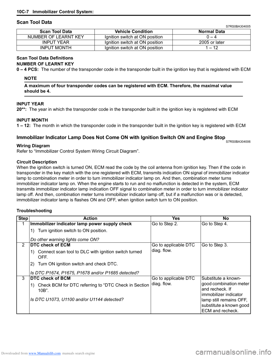
Scan Tool DataS7RS0BA304005
Scan Tool Data Definitions
NUMBER OF LEARNT KEY
0 – 4 PCS: The number of the transponder code in the transponder built in the ignition key that is registered with ECM
NOTE
A maximum of four transponder codes can be registered with ECM. Therefore, the maximal value
should be 4.
INPUT YEAR
20**: The year in which the transponder code in the transpon der built in the ignition key is registered with ECM
INPUT MONTH
1 – 12: The month in which the transponder code in the transpond er built in the ignition key is registered with ECM
Immobilizer Indicator Lamp Does Not Come ON with Ignition Switch ON and Engine StopS7RS0BA304006
Wiring Diagram
Refer to “Immobilizer Control System Wiring Circuit Diagram”.
Circuit Description
When the ignition switch is turned ON, ECM read the code by the coil antenna from ignition key. Then if the code in
transponder in the key match with the one registered with ECM, transmits indication ON signal of immobilizer indicator
lamp to combination meter in order to turn immobilizer indicator lamp on. And then, combination meter turns
immobilizer indicator lamp on. When th e engine starts to run and no malfunction is detected in the system, ECM
transmits immobilizer indi cator lamp indication OFF signal to combination meter in order to turn immobilizer indicator
lamp off. And then, comb ination meter turns immobilizer indicator lamp off, but if a malfunction was or is detected,
immobilizer indicator lamp is flashes ON and OF F, when ignition switch turn to ON position.
Troubleshooting Scan Tool Data Vehicl
e Condition Normal Data
NUMBER OF LEARNT KEY Ignition switch at ON position 0 – 4 INPUT YEAR Ignition switch at ON position 2005 or later
INPUT MONTH Ignition switch at ON position 1 – 12
Step Action YesNo
1 Immobilizer indicator lamp power supply check
1) Turn ignition switch to ON position.
Do other warning lights come ON? Go to Step 2.
Go to Step 4.
2 DTC check of ECM
1) Connect scan tool to DLC with ignition switch turned
OFF.
2) Turn ON ignition switch and check DTC.
Is DTC P1674, P1675, P1678 and/or P1685 detected? Go to applicable DTC
diag. flow.
Go to Step 3.
3 DTC check of BCM
1) Check BCM for DTC referring to “DTC Check in Section
10B”.
Is DTC U1073, U1100 and/or U1144 detected? Go to applicable DTC
diag. flow.
Substitute a known-
good combination meter
and recheck. If
immobilizer indicator
lamp still remains OFF,
substitute a known good
ECM and recheck.
Page 1451 of 1496
Downloaded from www.Manualslib.com manuals search engine Immobilizer Control System: 10C-8
Immobilizer Indicator Lamp Remains ON after Engine StartsS7RS0BA304007
Wiring Diagram
Refer to “Immobilizer Control S ystem Wiring Circuit Diagram”.
Circuit Description
When the ignition switch is turned ON, ECM read the code by the coil antenna from ignition key. Then if the code in
transponder in the key match with the one registered with ECM, transmits indication ON signal of immobilizer indicator
lamp to combination meter in order to turn immobilizer indicator lamp on. And then, combination meter turns
immobilizer indicator lamp on. When th e engine starts to run and no malfunction is detected in the system, ECM
transmits immobilizer indicator lamp indication O FF signal to combination meter in order to turn immobilizer indicator
lamp off. And then, comb ination meter turns immobilizer indicator lamp off, but if a malfunction was or is detected,
immobilizer indicator lamp is flashes ON and OF F, when ignition switch turn to ON position.
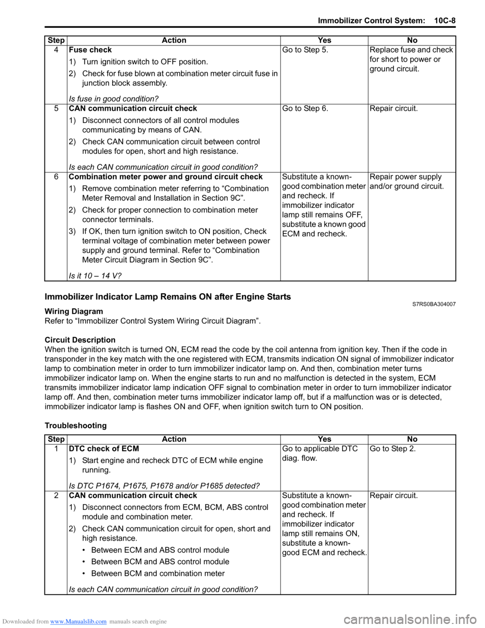
Troubleshooting 4
Fuse check
1) Turn ignition switch to OFF position.
2) Check for fuse blown at combination meter circuit fuse in
junction block assembly.
Is fuse in good condition? Go to Step 5. Replace fuse and check
for short to power or
ground circuit.
5 CAN communication circuit check
1) Disconnect connectors of all control modules
communicating by means of CAN.
2) Check CAN communication circuit between control modules for open, short and high resistance.
Is each CAN communication circuit in good condition? Go to Step 6. Repair circuit.
6 Combination meter power and ground circuit check
1) Remove combination meter referring to “Combination
Meter Removal and Installation in Section 9C”.
2) Check for proper connection to combination meter connector terminals.
3) If OK, then turn ignition switch to ON position, Check terminal voltage of combination meter between power
supply and ground terminal. Refer to “Combination
Meter Circuit Diagram in Section 9C”.
Is it 10 – 14 V? Substitute a known-
good combination meter
and recheck. If
immobilizer indicator
lamp still remains OFF,
substitute a known good
ECM and recheck.
Repair power supply
and/or ground circuit.
Step Action Yes No
Step
Action YesNo
1 DTC check of ECM
1) Start engine and recheck DTC of ECM while engine
running.
Is DTC P1674, P1675, P1678 and/or P1685 detected? Go to applicable DTC
diag. flow.
Go to Step 2.
2 CAN communication circuit check
1) Disconnect connectors from ECM, BCM, ABS control
module and combination meter.
2) Check CAN communication circuit for open, short and high resistance.
• Between ECM and ABS control module
• Between BCM and ABS control module
• Between BCM and combination meter
Is each CAN communication circuit in good condition? Substitute a known-
good combination meter
and recheck. If
immobilizer indicator
lamp still remains ON,
substitute a known-
good ECM and recheck.
Repair circuit.
Page 1454 of 1496
Downloaded from www.Manualslib.com manuals search engine 10C-11 Immobilizer Control System:
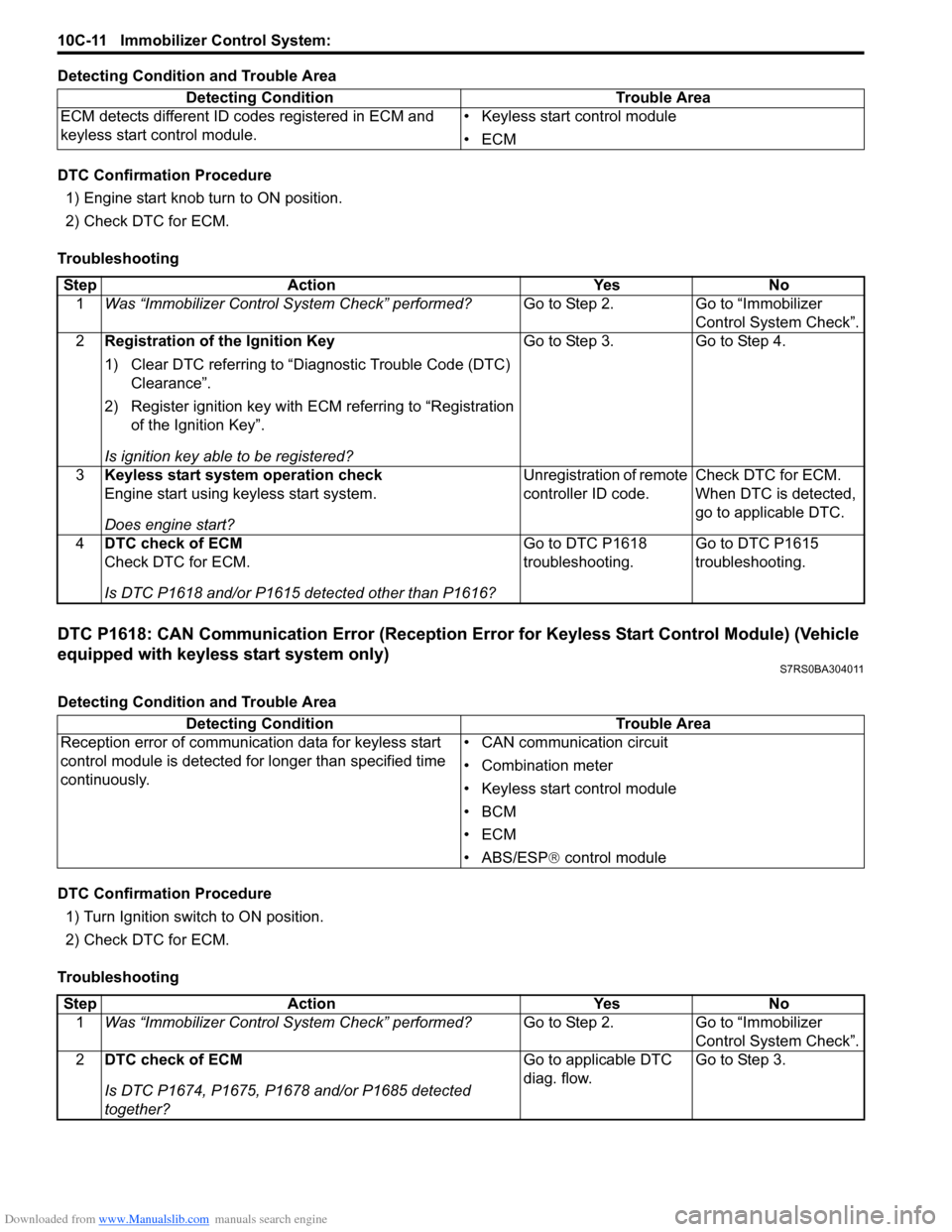
Detecting Condition and Trouble Area
DTC Confirmation Procedure1) Engine start knob turn to ON position.
2) Check DTC for ECM.
Troubleshooting
DTC P1618: CAN Communication Error (Reception Error for Keyless Start Control Module) (Vehicle
equipped with keyless start system only)
S7RS0BA304011
Detecting Condition and Trouble Area
DTC Confirmation Procedure 1) Turn Ignition switch to ON position.
2) Check DTC for ECM.
Troubleshooting Detecting Condition Trouble Area
ECM detects different ID codes registered in ECM and
keyless start control module. • Keyless start control module
•ECM
Step
Action YesNo
1 Was “Immobilizer Control S ystem Check” performed? Go to Step 2.Go to “Immobilizer
Control System Check”.
2 Registration of the Ignition Key
1) Clear DTC referring to “Diagnostic Trouble Code (DTC)
Clearance”.
2) Register ignition key with ECM referring to “Registration of the Ignition Key”.
Is ignition key able to be registered? Go to Step 3.
Go to Step 4.
3 Keyless start system operation check
Engine start using keyless start system.
Does engine start? Unregistration of remote
controller ID code.
Check DTC for ECM.
When DTC is detected,
go to applicable DTC.
4 DTC check of ECM
Check DTC for ECM.
Is DTC P1618 and/or P1615 detected other than P1616? Go to DTC P1618
troubleshooting.
Go to DTC P1615
troubleshooting.
Detecting Condition
Trouble Area
Reception error of communication data for keyless start
control module is detected for longer than specified time
continuously. • CAN communication circuit
• Combination meter
• Keyless start control module
•BCM
•ECM
• ABS/ESP®
control module
Step Action YesNo
1 Was “Immobilizer Control S ystem Check” performed? Go to Step 2.Go to “Immobilizer
Control System Check”.
2 DTC check of ECM
Is DTC P1674, P1675, P1678 and/or P1685 detected
together? Go to applicable DTC
diag. flow.
Go to Step 3.
Page 1457 of 1496
Downloaded from www.Manualslib.com manuals search engine Immobilizer Control System: 10C-14
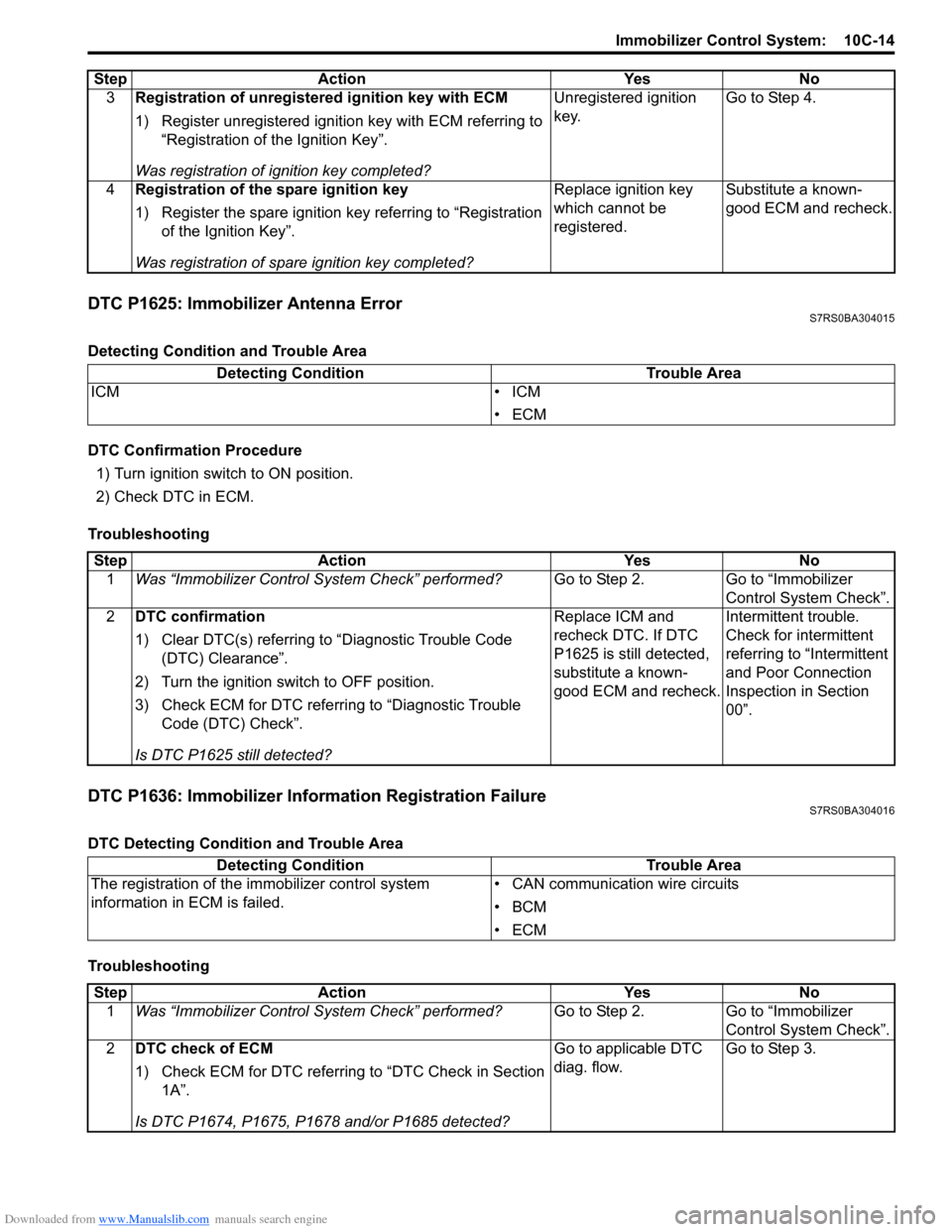
DTC P1625: Immobilizer Antenna ErrorS7RS0BA304015
Detecting Condition and Trouble Area
DTC Confirmation Procedure1) Turn ignition switch to ON position.
2) Check DTC in ECM.
Troubleshooting
DTC P1636: Immobilizer Information Registration FailureS7RS0BA304016
DTC Detecting Condition and Trouble Area
Troubleshooting 3
Registration of unregistered ignition key with ECM
1) Register unregistered igniti on key with ECM referring to
“Registration of the Ignition Key”.
Was registration of ignition key completed? Unregistered ignition
key.
Go to Step 4.
4 Registration of the spare ignition key
1) Register the spare ignition key referring to “Registration
of the Ignition Key”.
Was registration of spare ignition key completed? Replace ignition key
which cannot be
registered.
Substitute a known-
good ECM and recheck.
Step Action Yes No
Detecting Condition
Trouble Area
ICM • ICM
•ECM
StepAction YesNo
1 Was “Immobilizer Control S ystem Check” performed? Go to Step 2.Go to “Immobilizer
Control System Check”.
2 DTC confirmation
1) Clear DTC(s) referring to “Diagnostic Trouble Code
(DTC) Clearance”.
2) Turn the ignition switch to OFF position.
3) Check ECM for DTC referring to “Diagnostic Trouble Code (DTC) Check”.
Is DTC P1625 still detected? Replace ICM and
recheck DTC. If DTC
P1625 is still detected,
substitute a known-
good ECM and recheck.
Intermittent trouble.
Check for intermittent
referring to “Intermittent
and Poor Connection
Inspection in Section
00”.
Detecting Condition
Trouble Area
The registration of the immobilizer control system
information in ECM is failed. • CAN communication wire circuits
•BCM
•ECM
Step
Action YesNo
1 Was “Immobilizer Control S ystem Check” performed? Go to Step 2.Go to “Immobilizer
Control System Check”.
2 DTC check of ECM
1) Check ECM for DTC referring to “DTC Check in Section
1A”.
Is DTC P1674, P1675, P1678 and/or P1685 detected? Go to applicable DTC
diag. flow.
Go to Step 3.