2008 SUZUKI SWIFT module can
[x] Cancel search: module canPage 1043 of 1496
Downloaded from www.Manualslib.com manuals search engine Air Bag System: 8B-5
• When an open in air bag wire harness, damaged wire harness, connector or terminal is found, replace wire
harness, connectors and terminals as an assembly.
• When installing it, be careful so that the air bag wire harness is not caught or does not interfere with other
parts.
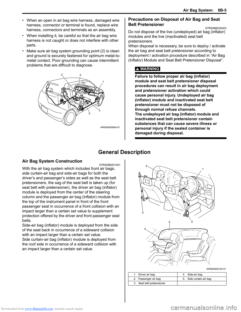
• Make sure air bag system grounding point (2) is clean and ground is securely fastened for optimum metal-to-
metal contact. Poor grounding can cause intermittent
problems that are difficult to diagnose.Precautions on Disposal of Air Bag and Seat
Belt Pretensioner
S7RS0B8200003
Do not dispose of the live (undeployed) air bag (inflator)
modules and the live (inactivated) seat belt
pretensioners.
When disposal is necessary, be sure to deploy / activate
the air bag and seat belt pretensioner according to
deployment / activation procedure described in “Air Bag
(Inflator) Module and Seat Belt Pretensioner Disposal”.
WARNING!
Failure to follow proper air bag (inflator)
module and seat belt pretensioner disposal
procedures can result in air bag deployment
and pretensioner activation which could
cause personal injury. Undeployed air bag
(inflator) module and inactivated seat belt
pretensioner must not be disposed of
through normal refuse channels.
The undeployed air bag (inflator) module and
inactivated seat belt pretensioner contain
substances that can cause severe illness or
personal injury if the sealed container is
damaged during disposal.
General Description
Air Bag System ConstructionS7RS0B8201001
With the air bag system which includes front air bags,
side curtain-air bag and side-air bags for both the
driver’s and passenger’s sides as well as the seat belt
pretensioners, the sag of the s eat belt is taken up (for
seat belt with pretensioner), the driver air bag (inflator)
module is deployed from th e center of the steering
column and the passenger air bag (inflator) module from
the top of the instrument panel in front of the front
passenger seat in occurrence of a front collision with an
impact larger than a certain set value to supplement
protection offered by the driver and front passenger seat
belts.
Side-air bag (inflator) module is deployed from the side
of the seat back in occurrence of a sideward collision
with an impact larger than a certain set value.
Side curtain-air bag (inflator) module is deployed from
the roof side in occurrence of a sideward collision with
an impact larger than a certain set value.
1
2
3
4
5
I4RS0A820004-01
1. Driver air bag 4. Side-air bag
2. Passenger air bag 5. Side curtain-air bag
3. Seat belt pretensioner
I4RS0A820102-01
Page 1049 of 1496
Downloaded from www.Manualslib.com manuals search engine Air Bag System: 8B-11
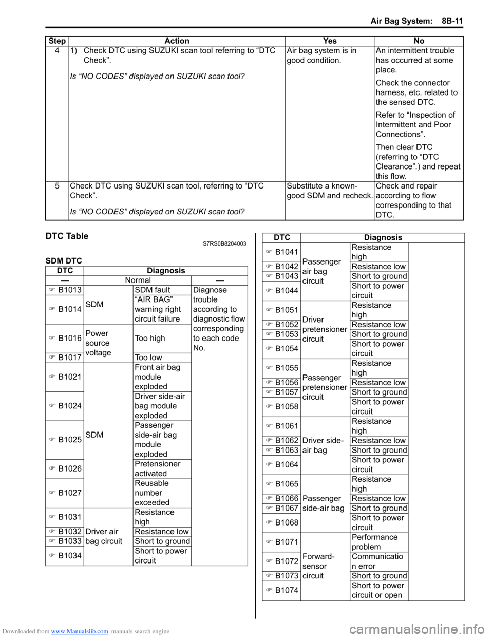
DTC TableS7RS0B8204003
SDM DTC4 1) Check DTC using SUZUKI scan tool referring to “DTC
Check”.
Is “NO CODES” displayed on SUZUKI scan tool? Air bag system is in
good condition.
An intermittent trouble
has occurred at some
place.
Check the connector
harness, etc. related to
the sensed DTC.
Refer to “Inspection of
Intermittent and Poor
Connections”.
Then clear DTC
(referring to “DTC
Clearance”.) and repeat
this flow.
5 Check DTC using SUZUKI scan tool, referring to “DTC Check”.
Is “NO CODES” displayed on SUZUKI scan tool? Substitute a known-
good SDM and recheck.
Check and repair
according to flow
corresponding to that
DTC.
Step Action Yes No
DTC
Diagnosis
—N orm al —
�) B1013
SDM SDM fault Diagnose
trouble
according to
diagnostic flow
corresponding
to each code
No.
�)
B1014 “AIR BAG”
warning right
circuit failure
�) B1016 Power
source
voltage Too high
�) B1017 Too low
�) B1021
SDM Front air bag
module
exploded
�) B1024 Driver side-air
bag module
exploded
�) B1025 Passenger
side-air bag
module
exploded
�) B1026 Pretensioner
activated
�) B1027 Reusable
number
exceeded
�) B1031
Driver air
bag circuit Resistance
high
�) B1032 Resistance low
�) B1033 Short to ground
�) B1034 Short to power
circuit
�)
B1041
Passenger
air bag
circuit Resistance
high
�) B1042 Resistance low
�) B1043 Short to ground
�) B1044 Short to power
circuit
�) B1051
Driver
pretensioner
circuit Resistance
high
�) B1052 Resistance low
�) B1053 Short to ground
�) B1054 Short to power
circuit
�) B1055
Passenger
pretensioner
circuit Resistance
high
�) B1056 Resistance low
�) B1057 Short to ground
�) B1058 Short to power
circuit
�) B1061
Driver side-
air bag Resistance
high
�) B1062 Resistance low
�) B1063 Short to ground
�) B1064 Short to power
circuit
�) B1065
Passenger
side-air bag Resistance
high
�) B1066 Resistance low
�) B1067 Short to ground
�) B1068 Short to power
circuit
�) B1071
Forward-
sensor
circuit Performance
problem
�) B1072 Communicatio
n error
�) B1073 Short to ground
�) B1074 Short to power
circuit or open
DTC Diagnosis
Page 1062 of 1496
Downloaded from www.Manualslib.com manuals search engine 8B-24 Air Bag System:
DTC B1027: Reusable Number ExceededS7RS0B8204017
DTC Will Set when
The SDM has not been replaced though the side-air bag developed several times in the past.
NOTE
DTC B1027 can never be cleared once it has been set.
DTC Trouble shooting1) Turn ignition switch OFF.
2) Replace SDM.
3) Repeat “Air Bag Diagnostic System Check”.
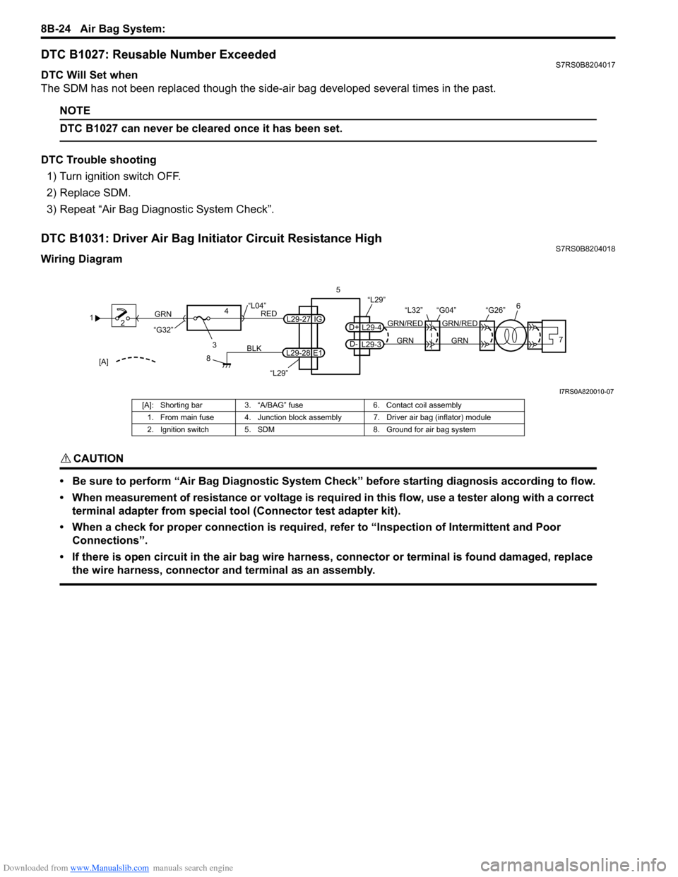
DTC B1031: Driver Air Bag Initiator Circuit Resistance HighS7RS0B8204018
Wiring Diagram
CAUTION!
• Be sure to perform “Air Bag Diagnostic System Check” before starting diagnosis according to flow.
• When measurement of resistance or voltage is required in this flow, use a tester along with a correct terminal adapter from special tool (Connector test adapter kit).
• When a check for proper connection is required, refer to “Inspection of Intermittent and Poor Connections”.
• If there is open circuit in the air bag wire harnes s, connector or terminal is found damaged, replace
the wire harness, connector and terminal as an assembly.
1 2
3
GRN
RED
8
BLK
L29-27
L29-28 IG
E1
4
“L29”
“L04”
“G32”
“L29”
L29-4
D+
L29-3
D-GRN
GRN/RED
GRN
GRN/RED 6
57
“G26”
“L32” “G04”
[A]
I7RS0A820010-07
[A]: Shorting bar 3. “A/BAG” fuse 6. Contact coil assembly
1. From main fuse 4. Junction block assembly 7. Driver air bag (inflator) module
2. Ignition switch 5. SDM 8. Ground for air bag system
Page 1135 of 1496
Downloaded from www.Manualslib.com manuals search engine Air Bag System: 8B-97
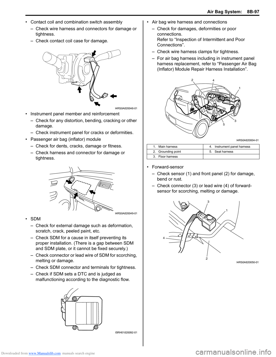
• Contact coil and combination switch assembly
– Check wire harness and connectors for damage or tightness.
– Check contact coil case for damage.
• Instrument panel member and reinforcement – Check for any distortion, bending, cracking or other damage.
– Check instrument panel fo r cracks or deformities.
• Passenger air bag (inflator) module
– Check for dents, cracks, damage or fitness.
– Check harness and connector for damage or tightness.
•SDM – Check for external damage such as deformation, scratch, crack, peeled paint, etc.
– Check SDM for a cause in itself preventing its proper installation. (There is a gap between SDM
and SDM plate, or it cannot be fixed securely.)
– Check connector or lead wire of SDM for scorching, melting or damage.
– Check SDM connector and terminals for tightness.
– Check if SDM sets a DTC and is judged as malfunctioning according to the diagnostic flow. • Air bag wire harness and connections
– Check for damages, deformities or poor connections.
Refer to “Inspection of Intermittent and Poor
Connections”.
– Check wire harness clamps for tightness.
– For air bag harness including in instrument panel harness replacement, refer to “Passenger Air Bag
(Inflator) Module Repair Harness Installation”.
• Forward-sensor – Check sensor (1) and front panel (2) for damage, bend or rust.
– Check connector (3) or lead wire (4) of forward- sensor for scorching, melting or damage.
I4RS0A820048-01
I4RS0A820049-01
I5RH01820092-01
1. Main harness 4. Instrument panel harness
2. Grounding point 5. Seat harness
3. Floor harness
1
2
3
4
5
I4RS0A820004-01
1
3
2
4
I4RS0A820050-01
Page 1144 of 1496
Downloaded from www.Manualslib.com manuals search engine 8B-106 Air Bag System:
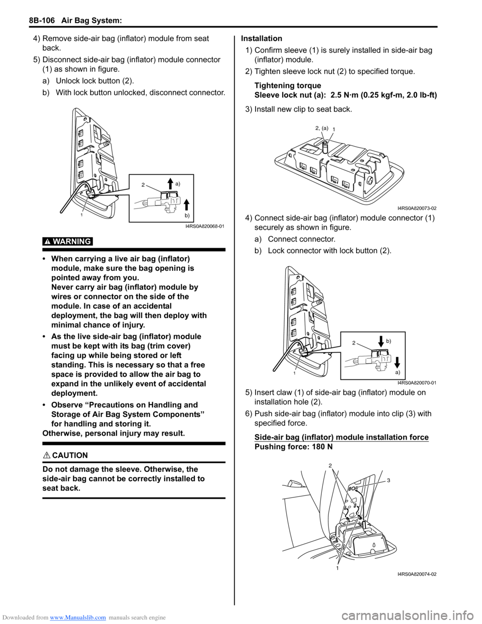
4) Remove side-air bag (inflator) module from seat back.
5) Disconnect side-air bag (inflator) module connector (1) as shown in figure.
a) Unlock lock button (2).
b) With lock button unlocked, disconnect connector.
WARNING!
• When carrying a live air bag (inflator) module, make sure the bag opening is
pointed away from you.
Never carry air bag (inflator) module by
wires or connector on the side of the
module. In case of an accidental
deployment, the bag will then deploy with
minimal chance of injury.
• As the live side-air bag (inflator) module must be kept with its bag (trim cover)
facing up while being stored or left
standing. This is necessary so that a free
space is provided to allow the air bag to
expand in the unlikely event of accidental
deployment.
• Observe “Precautions on Handling and Storage of Air Bag System Components”
for handling and storing it.
Otherwise, personal injury may result.
CAUTION!
Do not damage the sleeve. Otherwise, the
side-air bag cannot be correctly installed to
seat back.
Installation
1) Confirm sleeve (1) is surely installed in side-air bag (inflator) module.
2) Tighten sleeve lock nut (2) to specified torque.
Tightening torque
Sleeve lock nut (a): 2.5 N·m (0.25 kgf-m, 2.0 lb-ft)
3) Install new clip to seat back.
4) Connect side-air bag (inflator) module connector (1) securely as shown in figure.
a) Connect connector.
b) Lock connector wi th lock button (2).
5) Insert claw (1) of side-air bag (inflator) module on installation hole (2).
6) Push side-air bag (inflator) module into clip (3) with
specified force.
Side-air bag (inflator) module installation force
Pushing force: 180 N
2
1
a)
b)
I4RS0A820068-01
12, (a)
I4RS0A820073-02
1
2 a)
b)
I4RS0A820070-01
1
2
3
I4RS0A820074-02
Page 1151 of 1496
Downloaded from www.Manualslib.com manuals search engine Air Bag System: 8B-113
Air Bag (Inflator) Module and Seat Belt
Pretensioner Disposal
S7RS0B8206018
WARNING!
Failure to follow proper air bag (inflator)
module and seat belt pretensioner disposal
procedures can result in air bag deployment
and pretensioner activation which may cause
personal injury. Do not dispose of live
(undeployed) air bag (inflator) modules and
seat belt pretensioners. Because undeployed
air bag (inflator) module / inactivated seat
belt pretensioner must not be disposed of
through normal refuse channels. Undeployed
air bag (inflator) module and inactivated seat
belt pretensioner contain substances that
can cause severe illness or personal injury if
sealed container is damaged during disposal.
Air bag (inflator) module / seat belt pretensioner can be
deployed / activated inside or outside of vehicle.
Deployment / Activation method used depends upon
final disposition of vehicle. Review the following
instructions in order to deter mine which will work best in
a given situation.
Deployment / Activation Ou tside of Vehicle: When you
intend to return the vehicle to service, deploy the air bag
(inflator) module(s) and/or activate seat belt
pretensioner(s) outside of the vehicle.
Deployment / Activation Insi de of Vehicle: When the
vehicle will be destroyed, or salvaged for component
parts, deploy the air bag module(s) and/or activate seat
belt pretensioner(s) installed on vehicle.
WARNING!
The following precautions must be observed
for this work. Failure to observe any of them
may result in personal injury.
• Procedure should be followed strictly as described here.
• Be sure to read “Precautions on Service and Diagnosis of Air Bag System”
beforehand.
• To avoid accidental deployment / activation, this work should be performed
by no more than one person.
• Since smoke is produced when air bag (inflator) module is deployed and
pretensioner is activated, select well-
ventilated area.
• Air bag (inflator) module and seat belt pretensioner will immediately deploy /
activate when 12 volts vehicle battery is
connected to it. Wear safety glasses
throughout this entire deployment /
activation and disposal procedure.
• Wear suitable ear protection when deploying air bag (inflator) module /
activating seat belt pretensioner. Also,
advise those who are in area close to
deployment / activation site to wear
suitable ear protection.
• Do not deploy / activate two or more air bag system components (air bag (inflator)
modules and seat belt pretensioners) at
the same time.
• Never connect deployment harness to any 12 volts vehicle battery before connecting
deployment harness to air bag (inflator)
module and seat belt pretensioner.
Deployment harness sh all remain shorted
and not be connected to 12 volts vehicle
battery till you are ready to deploy air bag
(inflator) module or activate seat belt
pretensioner.
Page 1155 of 1496
Downloaded from www.Manualslib.com manuals search engine Air Bag System: 8B-117
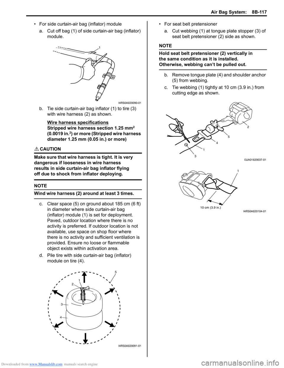
• For side curtain-air bag (inflator) modulea. Cut off bag (1) of side curtain-air bag (inflator) module.
b. Tie side curtain-air bag inflator (1) to tire (3) with wire harness (2) as shown.
Wire harness specifications
Stripped wire harness section 1.25 mm2
(0.0019 in.2) or more (Stripped wire harness
diameter 1.25 mm (0.05 in.) or more)
CAUTION!
Make sure that wire harness is tight. It is very
dangerous if looseness in wire harness
results in side curtain-air bag inflator flying
off due to shock from inflator deploying.
NOTE
Wind wire harness (2) around at least 3 times.
c. Clear space (5) on ground about 185 cm (6 ft) in diameter where side curtain-air bag
(inflator) module (1) is set for deployment.
Paved, outdoor location where there is no
activity is preferred. If outdoor location is not
available, use space on shop floor where
there is no activity and sufficient ventilation is
provided. Ensure no loose or flammable
object exists within activation area.
d. Pile tire with side curtain-air bag (inflator) module on tire (4). • For seat belt pretensioner
a. Cut webbing (1) at tongue plate stopper (3) of seat belt pretensioner (2) side as shown.
NOTE
Hold seat belt pretensioner (2) vertically in
the same condition as it is installed.
Otherwise, webbing can’t be pulled out.
b. Remove tongue plate (4) and shoulder anchor (5) from webbing.
c. Tie webbing (1) tightly at 10 cm (3.9 in.) from
cutting edge as shown.
1
I4RS0A820090-01
1
2
3
4
5
I4RS0A820091-01
3 1 4
5 2I3JA01820037-01
10 cm (3.9 in.)
1
I4RS0A820104-01
Page 1160 of 1496
Downloaded from www.Manualslib.com manuals search engine 8B-122 Air Bag System:
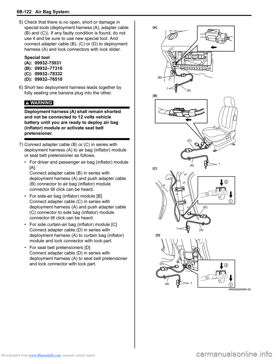
5) Check that there is no open, short or damage in special tools (deployment harness (A), adapter cable
(B) and (C)). If any faulty condition is found, do not
use it and be sure to use new special tool. And
connect adapter cable (B), (C) or (D) to deployment
harness (A) and lock connectors with lock slider.
Special tool
(A): 09932-75031
(B): 09932–77310
(C): 09932–78332
(D): 09932–76510
6) Short two deployment harness leads together by fully seating one banana plug into the other.
WARNING!
Deployment harness (A) shall remain shorted
and not be connected to 12 volts vehicle
battery until you are ready to deploy air bag
(inflator) module or activate seat belt
pretensioner.
7) Connect adapter cable (B) or (C) in series with deployment harness (A) to air bag (inflator) module
or seat belt pretensioner as follows.
• For driver and passenger air bag (inflator) module [A]
Connect adapter cable (B) in series with
deployment harness (A) and push adapter cable
(B) connector to air bag (inflator) module
connector till click can be heard.
• For side-air bag (inflator) module [B] Connect adapter cable (C) in series with
deployment harness (A) and push adapter cable
(C) connector to side bag (inflator) module
connector till click can be heard.
• For side curtain-air bag (inflator) module [C] Connect adapter cable (D) in series with
deployment harness (A) to curtain bag (inflator)
module and lock connector with lock part.
• For seat belt pretensioners [D] Connect adapter cable (D) in series with
deployment harness (A) to seat belt pretensioner
and lock connector with lock part.
[A]
[C]
[D]
1
2
1
2
1
(B) (A)
[B]
1
(C)
(A)
1
(D)
(A)
(A)
(D)
1
I4RS0A820094-02