2008 SUZUKI SWIFT temp
[x] Cancel search: tempPage 317 of 1496
Downloaded from www.Manualslib.com manuals search engine Engine Mechanical: 1D-32
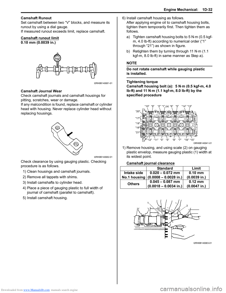
Camshaft Runout
Set camshaft between two “V” blocks, and measure its
runout by using a dial gauge.
If measured runout exceeds limit, replace camshaft.
Camshaft runout limit
0.10 mm (0.0039 in.)
Camshaft Journal Wear
Check camshaft journals and camshaft housings for
pitting, scratches, wear or damage.
If any malcondition is found, replace camshaft or cylinder
head with housing. Never re place cylinder head without
replacing housings.
Check clearance by using ga uging plastic. Checking
procedure is as follows.
1) Clean housings and camshaft journals.
2) Remove all tappets with shims.
3) Install camshafts to cylinder head.
4) Place a piece of gauging plastic to full width of
journal of camshaft (parallel to camshaft).
5) Install camshaft housing. 6) Install camshaft housing as follows.
After applying engine oil to camshaft housing bolts,
tighten them temporarily first. Then tighten them as
follows.
a) Tighten camshaft housing bolts to 5 N ⋅m (0.5 kgf-
m, 4.0 lb-ft) according to numerical order (“1”
through “21”) as shown in figure.
b) Retighten them by turning through 11 N ⋅m (1.1
kgf-m, 8.0 lb-ft) in same manner as Step a).
NOTE
Do not rotate camshaft while gauging plastic
is installed.
Tightening torque
Camshaft housing bolt (a): 5 N ⋅m (0.5 kgf-m, 4.0
lb-ft) and 11 N ⋅m (1.1 kgf-m, 8.0 lb-ft) by the
specified procedure
1) Remove housing, and using scale (2) on gauging plastic envelop, measure gauging plastic (1) width at
its widest point.
Camshaft journal clearanceI2RH0B140081-01
I2RH0B140082-01
Standard Limit
Intake side
No.1 housing 0.020 – 0.072 mm
(0.0008 – 0.0028 in.) 0.10 mm
(0.0039 in.)
Others 0.045 – 0.087 mm
(0.0018 – 0.0034 in.) 0.12 mm
(0.0047 in.)
“10”“9” “2” “1”,(a) “6” “5” “14” “13”
“20”
“17” “19”
“18”
“21”
“12”“11”
“4” “3” “8” “7” “16” “15”
I3RH0B140041-01
I2RH0B140083-01
Page 323 of 1496
Downloaded from www.Manualslib.com manuals search engine Engine Mechanical: 1D-38
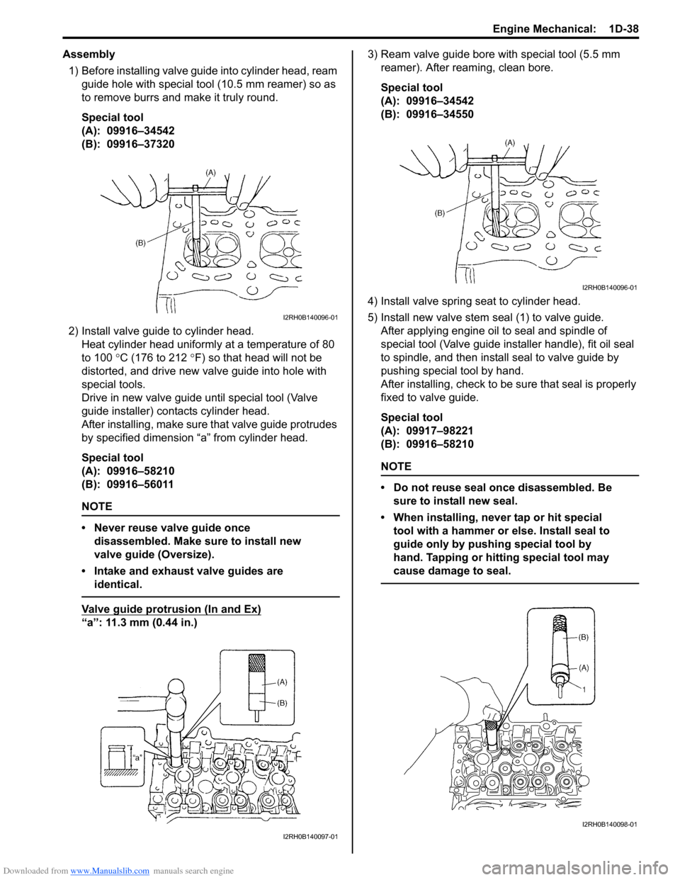
Assembly1) Before installing valve guide into cylinder head, ream
guide hole with special tool (10.5 mm reamer) so as
to remove burrs and make it truly round.
Special tool
(A): 09916–34542
(B): 09916–37320
2) Install valve guide to cylinder head. Heat cylinder head uniformly at a temperature of 80
to 100 °C (176 to 212 °F) so that head will not be
distorted, and drive new valve guide into hole with
special tools.
Drive in new valve guide until special tool (Valve
guide installer) contacts cylinder head.
After installing, ma ke sure that valve guide pr otrudes
by specified dimension “a” from cylinder head.
Special tool
(A): 09916–58210
(B): 09916–56011
NOTE
• Never reuse valve guide once disassembled. Make sure to install new
valve guide (Oversize).
• Intake and exhaust valve guides are identical.
Valve guide protrusion (In and Ex)
“a”: 11.3 mm (0.44 in.) 3) Ream valve guide bore with special tool (5.5 mm
reamer). After reaming, clean bore.
Special tool
(A): 09916–34542
(B): 09916–34550
4) Install valve spring seat to cylinder head.
5) Install new valve stem seal (1) to valve guide. After applying engine oil to seal and spindle of
special tool (Valve guide installer handle), fit oil seal
to spindle, and then install seal to valve guide by
pushing special tool by hand.
After installing, check to be sure that seal is properly
fixed to valve guide.
Special tool
(A): 09917–98221
(B): 09916–58210
NOTE
• Do not reuse seal once disassembled. Be sure to install new seal.
• When installing, never tap or hit special tool with a hammer or else. Install seal to
guide only by pushing special tool by
hand. Tapping or hitting special tool may
cause damage to seal.
I2RH0B140096-01
I2RH0B140097-01
I2RH0B140096-01
I2RH0B140098-01
Page 355 of 1496

Downloaded from www.Manualslib.com manuals search engine Engine Lubrication System: 1E-3
6) Start engine and warm engine up to normal operating temperature.
NOTE
Be sure to shift transaxle gear shift lever in
“Neutral” (shift select lever in “P” range for
A/T vehicle), set parking brake and block
drive wheels.
7) After warming up, raise engine speed to 4,000 r/min. and measure oil pressure.
Oil pressure specification
More than 270 kPa (2.7 kg/cm2, 39.8 psi) at 4,000
r/min. (rpm)
8) After checking oil pressure, stop engine and remove oil pressure gauge and attachment.
9) Before reinstalling oil pressure switch (2), be sure to
wrap its screw threads with sealing tape (1) and
tighten switch to specified torque.
NOTE
If sealing tape edge is bulged out from screw
threads of switch, cut it off.
Tightening torque
Oil pressure switch (a): 13 N·m (1.3 kgf-m, 9.5
lb-ft) 10) Start engine and check oil pressure switch for oil
leakage. If oil leakage is found, repair it.
11) Connect oil pressure switch coupler (1).
Repair Instructions
Heat Exchanger ComponentsS7RS0B1506001
I2RH0B150005-01
I2RH0B150006-01
3
4
5
7
6
(a)
2
1
I6RS0B151001-02
1. Heat exchanger inlet No. 1 hose 4. Gasket7. O-ring
: Apply engine oil.
2. Heat exchanger outlet No. 1 hose 5. Heat exchanger stand bolt : 22 N⋅m (2.2 kgf-m, 16.0 lb-ft)
3. Heat exchanger 6. Oil filter adapter case : Do not reuse.
Page 358 of 1496
Downloaded from www.Manualslib.com manuals search engine 1E-6 Engine Lubrication System:
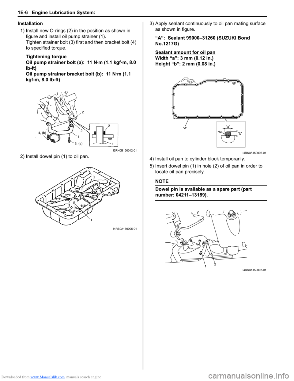
Installation1) Install new O-rings (2) in the position as shown in figure and install o il pump strainer (1).
Tighten strainer bolt (3) first and then bracket bolt (4)
to specified torque.
Tightening torque
Oil pump strainer bolt (a): 11 N·m (1.1 kgf-m, 8.0
lb-ft)
Oil pump strainer bracket bolt (b): 11 N·m (1.1
kgf-m, 8.0 lb-ft)
2) Install dowel pin (1) to oil pan. 3) Apply sealant continuously to oil pan mating surface
as shown in figure.
“A”: Sealant 99000–31260 (SUZUKI Bond
No.1217G)
Sealant amount for oil pan
Width “a”: 3 mm (0.12 in.)
Height “b”: 2 mm (0.08 in.)
4) Install oil pan to cy linder block temporarily.
5) Insert dowel pin (1) in hole (2) of oil pan in order to
locate oil pan precisely.
NOTE
Dowel pin is available as a spare part (part
number: 04211–13189).
I2RH0B150012-01
I4RS0A150005-01
I4RS0A150006-01
21I4RS0A150007-01
Page 364 of 1496

Downloaded from www.Manualslib.com manuals search engine 1F-1 Engine Cooling System:
Engine
Engine Cooling System
General Description
Cooling System DescriptionS7RS0B1601001
The cooling system consists of the radiator cap, radiator, coolant reservoir, hoses, water pump, cooling fan and
thermostat. The radiator is of tube-and-fin type.
Coolant DescriptionS7RS0B1601002
WARNING!
• Do not remove radiator cap to check engine coolant level; check coolant visually at the see-through coolant reservoir. Coolant should be added only to reservoir as necessary.
• As long as there is pressure in the cooling system, the temperature can be considerably higher than the boiling temperature of the solution in the radiator without causing the solution to boil. Removal
of the radiator cap while engine is hot and pressure is high will cause the solution to boil
instantaneously and possibly with explosive force, spewing the solution over engine, fenders and
person removing cap. If the solution contains flammable anti-freeze such as alcohol (not
recommended for use at any time), there is also the possibility of causing a serious fire.
• Check to make sure that engine coolant temperature is cold before removing any part of cooling system.
• Also be sure to disconnect negative cable from battery terminal before removing any part.
The coolant recovery system is standard. The coolant in the radiator expands with heat, and the coolant is overflowed
to the reservoir.
When the system cools down, the coolant is drawn back into the radiator.
The cooling system has be en filled with a quality coolant that is a 50/50 mixture of water and ethylene glycol
antifreeze.
This 50/50 mixture coolant solution provides freezing protection to –36 °C (–33 °F).
• Maintain cooling system freeze protection at –36 °C (–33 °F) to ensure protection against corrosion and loss of
coolant from boiling. This should be done even if freezing temperatures are not expected.
• Add ethylene glycol base coolant when coolant has to be added because of coolant loss or to provide added protection against freezing at temperature lower than –36 °C (–33 °F).
NOTE
• Alcohol or methanol base coolant or plain water alone should not be used in cooling system at any
time as damage to cooling system could occur.
• Coolant must be mixed with deminerated water or distilled water.
Anti-freeze proportioning table
For M/T model For A/T model
Freezing temperature °
C –36 –36
° F –33 –33
Anti-freeze / Anti-corrosion coolant concentration % 50 50
Ratio of compound to cooling water ltr. 3.10/3.10 3.05/3.05
US pt. 6.55/6.55 6.44/6.44
Imp pt. 5.46/5.46 5.37/5.37
Page 366 of 1496

Downloaded from www.Manualslib.com manuals search engine 1F-3 Engine Cooling System:
When coolant is warmed up to normal temperature and the thermostat opens, coolant passes through the radiator
core to be cooled as follows.
11
10 3 7
4
9
8
6
5
2 12 1
13
I6RS0C160002-01
1. Radiator inlet hose
6. Water pump11. Heater core
2. Radiator outlet hose 7. Throttle body12. Radiator
3. Throttle body inlet hose 8. Engine13. Heat exchanger
4. Throttle body outlet hose 9. Heater core inlet hose
5. Thermostat 10. Heater core outlet hose
Page 371 of 1496
Downloaded from www.Manualslib.com manuals search engine Engine Cooling System: 1F-8
Thermostat Removal and InstallationS7RS0B1606007
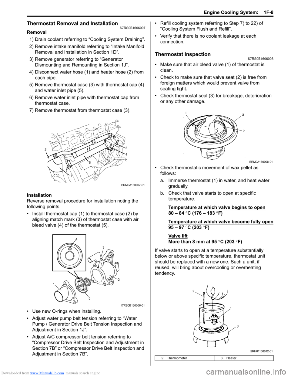
Removal1) Drain coolant referring to “Cooling System Draining”.
2) Remove intake manifold referring to “Intake Manifold Removal and Installa tion in Section 1D”.
3) Remove generator referring to “Generator Dismounting and Remounting in Section 1J”.
4) Disconnect water hose (1) and heater hose (2) from each pipe.
5) Remove thermostat case (3) with thermostat cap (4)
and water inlet pipe (5).
6) Remove water inlet pipe with thermostat cap from thermostat case.
7) Remove thermostat from thermostat case (3).
Installation
Reverse removal procedure for installation noting the
following points.
• Install thermostat cap (1) to thermostat case (2) by aligning match mark (3) of thermostat case with air
bleed valve (4) of the thermostat (5).
• Use new O-rings when installing.
• Adjust water pump belt tension referring to “Water Pump / Generator Drive Belt Tension Inspection and
Adjustment in Section 1J”.
• Adjust A/C compressor belt tension referring to “Compressor Drive Belt Inspection and Adjustment in
Section 7B” or “Compressor Drive Belt Inspection and
Adjustment in Section 7B”. • Refill cooling system referrin
g to Step 7) to 22) of
“Cooling System Flush and Refill”.
• Verify that there is no coolant leakage at each connection.
Thermostat InspectionS7RS0B1606008
• Make sure that air bleed valve (1) of thermostat is clean.
• Check to make sure that va lve seat (2) is free from
foreign matters which would prevent valve from
seating tight.
• Check thermostat seal (3) for breakage, deterioration or any other damage.
• Check thermostatic movement of wax pellet as follows:
a. Immerse thermostat (1) in water, and heat water gradually.
b. Check that valve starts to open at specific temperature.
Temperature at which valve begins to open
80 – 84 °C (176 – 183 °F)
Temperature at which valve become fully open
95 – 97 °C (203 °F)
Va l v e l i ft
More than 8 mm at 95 °C (203 ° F)
If valve starts to open at a temperature substantially
below or above specific temperature, thermostat unit
should be replaced with a new one. Such a unit, if
reused, will bring about ov ercooling or overheating
tendency.
I3RM0A160007-01
4
5 3
1 2
I7RS0B160006-01
2. Thermometer
3. Heater
I3RM0A160008-01
I2RH01160012-01
Page 376 of 1496
Downloaded from www.Manualslib.com manuals search engine 1G-1 Fuel System:
Engine
Fuel System
Precautions
Precautions on Fuel System ServiceS7RS0B1700001
WARNING!
Before attempting service of any type on fuel system, the following should be always observed in
order to reduce the risk of fire and personal injury.
• Disconnect negative cable at battery.
• Do not smoke, and place no smoking signs near work area.
• Be sure to have CO
2 fire extinguisher handy.
• Be sure to perform work in a well-ventilated area and away from any open flames (such as gas hot heater).
• Wear safety glasses.
• To relieve fuel vapor pressure in fuel tank, remove fuel filler cap from fuel filler neck and then
reinstall it.
• As fuel feed line is still under high fuel pr essure even after stopping engine, loosening or
disconnecting fuel feed line directly may cause dangerous spout of fuel. Before loosening or
disconnecting fuel feed line, make sure to relieve fuel pressure referring to “Fuel Pressure Relief
Procedure”.
• A small amount of fuel may be released when the fuel line is disconnected. In order to reduce the risk of personal injury, cover a shop cloth to the fitting to be disconnected. Be sure to put that cloth
in an approved container after disconnecting.
• Never run engine with fuel pump relay disconnected when engine and exhaust system are hot.
• Note that fuel hose connection varies with each type of pipe. Be sure to connect and clamp each hose correctly referring to “Fuel Hose Disconnecting and Reconnecting”.
After connecting, make sure that it has no twist or kink.
• When installing inje ctor or fuel feed pipe, lubr icate its O-ring with gasoline.
General Description
Fuel System DescriptionS7RS0B1701001
CAUTION!
This engine requires the unleaded fuel only.
The leaded and/or low lead fuel can result in
engine damage and reduce the effectiveness
of the emission control system.
The main components of the fuel system are fuel tank,
fuel pump assembly (with fuel filter, fuel level gauge, fuel
pressure regulator, fuel feed line and fuel vapor line.
For the details of fuel flow, refer to “Fuel Delivery System
Diagram”.
Fuel Delivery System DescriptionS7RS0B1701002
The fuel delivery system consists of the fuel tank, fuel
pump assembly (with built-in f uel filter and fuel pressure
regulator), delivery pipe, injectors and fuel feed line.
The fuel in the fuel tank is pumped up by the fuel pump,
sent into delivery pipe and injected by the injectors.
As the fuel pump assembly is equipped with built-in fuel
filter and fuel pressure regulator, the fuel is filtered and
its pressure is regulated before being sent to the feed
pipe.
The excess fuel at fuel pressure regulation process is
returned back into the fuel tank.
Also, fuel vapor generated in fuel tank is led through the
fuel vapor line into the EVAP canister.
For system diagram, refer to “Fuel Delivery System
Diagram”.