2008 SUZUKI SWIFT 001
[x] Cancel search: 001Page 336 of 1496
Downloaded from www.Manualslib.com manuals search engine 1D-51 Engine Mechanical:
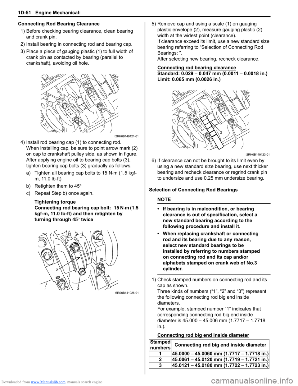
Connecting Rod Bearing Clearance1) Before checking bearing clearance, clean bearing and crank pin.
2) Install bearing in connecting rod and bearing cap.
3) Place a piece of gauging plastic (1) to full width of crank pin as contacted by bearing (parallel to
crankshaft), avoiding oil hole.
4) Install rod bearing cap (1) to connecting rod. When installing cap, be sure to point arrow mark (2)
on cap to crankshaft pulley side, as shown in figure.
After applying engine oil to bearing cap bolts (3),
tighten bearing cap bolts (3) gradually as follows.
a) Tighten all bearing cap bolts to 15 N ⋅m (1.5 kgf-
m, 11.0 lb-ft)
b) Retighten them to 45°
c) Repeat Step b) once again.
Tightening torque
Connecting rod bearing cap bolt: 15 N ⋅m (1.5
kgf-m, 11.0 lb-ft) and then retighten by
turning through 45 ° twice 5) Remove cap and using a scale (1) on gauging
plastic envelope (2), measure gauging plastic (2)
width at the widest point (clearance).
If clearance exceed its limit, use a new standard size
bearing referring to “Selection of Connecting Rod
Bearings: ”.
After selecting new bearing, recheck clearance.
Connecting rod bearing clearance
Standard: 0.029 – 0.047 mm (0.0011 – 0.0018 in.)
Limit: 0.065 mm (0.0026 in.)
6) If clearance can not be brought to its limit even by using a new standard size bearing, use next thicker
bearing and recheck clearance or regrind crank pin
to undersize and use 0.25 mm undersize bearing.
Selection of Connecting Rod Bearings
NOTE
• If bearing is in malcondition, or bearing clearance is out of specification, select a
new standard bearing according to the
following procedure and install it.
• When replacing crankshaft or connecting rod and its bearing due to any reason,
select new standard bearings to be
installed by referring to numbers stamped
on connecting rod and its cap and/or
alphabets stamped on crank web of No.3
cylinder.
1) Check stamped numbers on connecting rod and its cap as shown.
Three kinds of numbers (“1”, “2” and “3”) represent
the following connecting rod big end inside
diameters.
For example, stamped number “1” indicates that
corresponding connecting rod big end inside
diameter is 45.000 – 45.006 mm (1.7717 – 1.7718
in.).
Connecting rod big end inside diameter
I2RH0B140121-01
I6RS0B141026-01
Stamped
numbers Connecting rod big end inside diameter
1 45.0000 – 45.0060 mm (1.7717 – 1.7718 in.)
2 45.0061 – 45.0120 mm (1.7719 – 1.7721 in.)
3 45.0121 – 45.0180 mm (1.7722 – 1.7723 in.)
I2RH0B140123-01
Page 337 of 1496
Downloaded from www.Manualslib.com manuals search engine Engine Mechanical: 1D-52
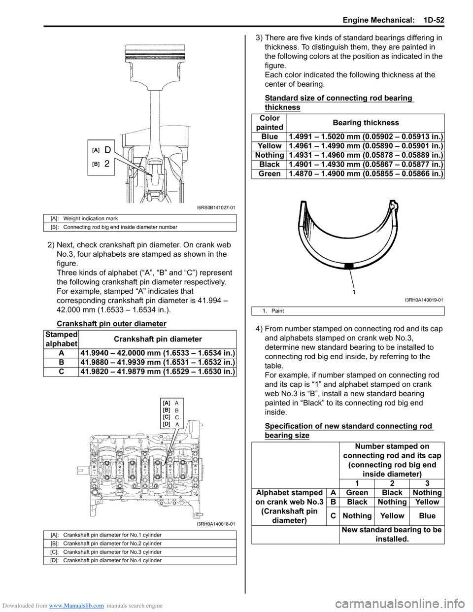
2) Next, check crankshaft pin diameter. On crank web No.3, four alphabets are stamped as shown in the
figure.
Three kinds of alphabet (“A”, “B” and “C”) represent
the following crankshaft pin diameter respectively.
For example, stamped “A” indicates that
corresponding crankshaft pin diameter is 41.994 –
42.000 mm (1.6533 – 1.6534 in.).
Crankshaft pin outer diameter
3) There are five kinds of standard bearings differing in thickness. To distinguish them, they are painted in
the following colors at the position as indicated in the
figure.
Each color indicated the following thickness at the
center of bearing.
Standard size of connecting rod bearing
thickness
4) From number stamped on connecting rod and its cap and alphabets stamped on crank web No.3,
determine new standard bearing to be installed to
connecting rod big end inside, by referring to the
table.
For example, if number stamped on connecting rod
and its cap is “1” and alphabet stamped on crank
web No.3 is “B”, install a new standard bearing
painted in “Black” to its connecting rod big end
inside.
Specification of new standard connecting rod
bearing size
[A]: Weight indication mark
[B]: Connecting rod big end inside diameter number
Stamped alphabet Crankshaft pin diameter
A 41.9940 – 42.0000 mm (1.6533 – 1.6534 in.)
B 41.9880 – 41.9939 mm (1.6531 – 1.6532 in.)
C 41.9820 – 41.9879 mm (1.6529 – 1.6530 in.)
[A]: Crankshaft pin diameter for No.1 cylinder
[B]: Crankshaft pin diameter for No.2 cylinder
[C]: Crankshaft pin diameter for No.3 cylinder
[D]: Crankshaft pin diameter for No.4 cylinder
I6RS0B141027-01
I3RH0A140018-01
Color
painted Bearing thickness
Blue 1.4991 – 1.5020 mm (0.05902 – 0.05913 in.)
Yellow 1.4961 – 1.4990 mm (0.05890 – 0.05901 in.)
Nothing 1.4931 – 1.4960 mm (0.05878 – 0.05889 in.) Black 1.4901 – 1.4930 mm (0.05867 – 0.05877 in.)
Green 1.4870 – 1.4900 mm (0.05855 – 0.05866 in.)
1. Paint
Number stamped on
connecting rod and its cap (connecting rod big end inside diameter)
123
Alphabet stamped
on crank web No.3 (Crankshaft pin diameter) A Green Black Nothing
B Black Nothing Yellow
C Nothing Yellow Blue
New standard bearing to be installed.
I3RH0A140019-01
Page 341 of 1496
Downloaded from www.Manualslib.com manuals search engine Engine Mechanical: 1D-56
5) Install crankshaft to cylinder block.
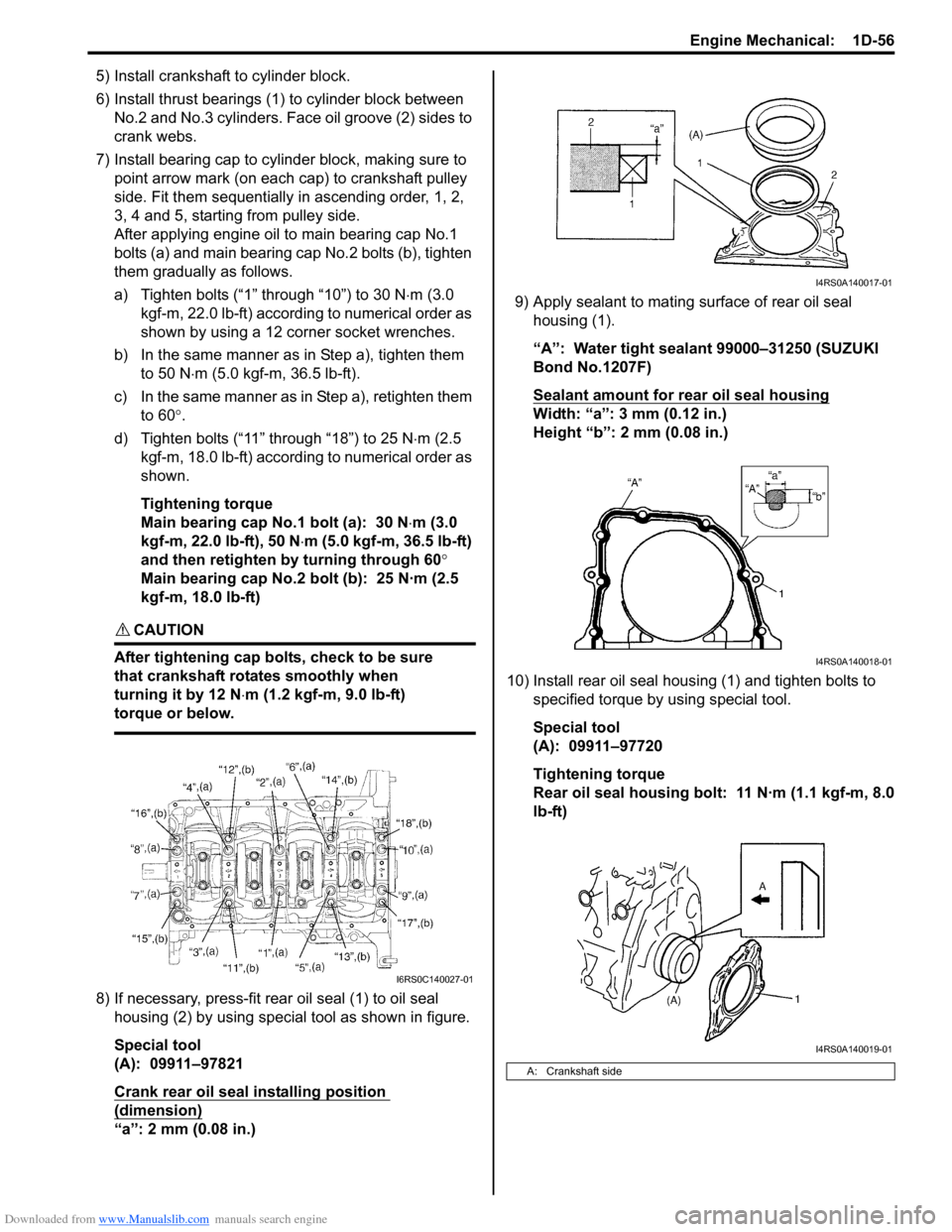
6) Install thrust bearings (1) to cylinder block between No.2 and No.3 cylinders. Face oil groove (2) sides to
crank webs.
7) Install bearing cap to cylinder block, making sure to point arrow mark (on each cap) to crankshaft pulley
side. Fit them sequentially in ascending order, 1, 2,
3, 4 and 5, starting from pulley side.
After applying engine oil to main bearing cap No.1
bolts (a) and main bearing cap No.2 bolts (b), tighten
them gradually as follows.
a) Tighten bolts (“1” through “10”) to 30 N ⋅m (3.0
kgf-m, 22.0 lb-ft) according to numerical order as
shown by using a 12 corner socket wrenches.
b) In the same manner as in Step a), tighten them to 50 N ⋅m (5.0 kgf-m, 36.5 lb-ft).
c) In the same manner as in Step a), retighten them to 60 °.
d) Tighten bolts (“11” through “18”) to 25 N ⋅m (2.5
kgf-m, 18.0 lb-ft) according to numerical order as
shown.
Tightening torque
Main bearing cap No.1 bolt (a): 30 N ⋅m (3.0
kgf-m, 22.0 lb-ft), 50 N ⋅m (5.0 kgf-m, 36.5 lb-ft)
and then retighten by turning through 60 °
Main bearing cap No.2 bolt (b): 25 N·m (2.5
kgf-m, 18.0 lb-ft)
CAUTION!
After tightening cap bolts, check to be sure
that crankshaft rotates smoothly when
turning it by 12 N ⋅m (1.2 kgf-m, 9.0 lb-ft)
torque or below.
8) If necessary, press-fit rear oil seal (1) to oil seal housing (2) by using special tool as shown in figure.
Special tool
(A): 09911–97821
Crank rear oil seal installing position
(dimension)
“a”: 2 mm (0.08 in.) 9) Apply sealant to mating surface of rear oil seal
housing (1).
“A”: Water tight sealant 99000–31250 (SUZUKI
Bond No.1207F)
Sealant amount for rear oil seal housing
Width: “a”: 3 mm (0.12 in.)
Height “b”: 2 mm (0.08 in.)
10) Install rear oil seal housing (1) and tighten bolts to specified torque by using special tool.
Special tool
(A): 09911–97720
Tightening torque
Rear oil seal housing bolt: 11 N·m (1.1 kgf-m, 8.0
lb-ft)
I6RS0C140027-01
A: Crankshaft side
I4RS0A140017-01
I4RS0A140018-01
I4RS0A140019-01
Page 344 of 1496
Downloaded from www.Manualslib.com manuals search engine 1D-59 Engine Mechanical:
Main Bearings InspectionS7RS0B1406038
General Information
• Service main bearings are available in standard size and 0.25 mm (0.0098 in.) undersize, and each of them
has 5 kinds of bearings differing in tolerance.
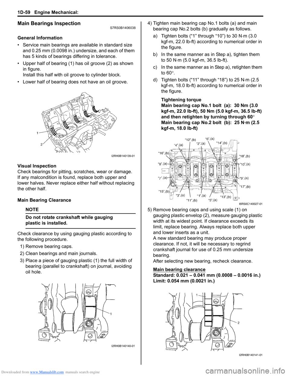
• Upper half of bearing (1) has oil groove (2) as shown in figure.
Install this half with o il groove to cylinder block.
• Lower half of bearing does not have an oil groove.
Visual Inspection
Check bearings for pitting, scratches, wear or damage.
If any malcondition is foun d, replace both upper and
lower halves. Never replace either half without replacing
the other half.
Main Bearing Clearance
NOTE
Do not rotate crankshaft while gauging
plastic is installed.
Check clearance by using ga uging plastic according to
the following procedure.
1) Remove bearing caps.
2) Clean bearings and main journals.
3) Place a piece of gauging plastic (1) the full width of bearing (parallel to crankshaft) on journal, avoiding
oil hole. 4) Tighten main bearing cap No.1 bolts (a) and main
bearing cap No.2 bolts (b) gradually as follows.
a) Tighten bolts (“1” through “10”) to 30 N ⋅m (3.0
kgf-m, 22.0 lb-ft) according to numerical order in
the figure.
b) In the same manner as in Step a), tighten them to 50 N ⋅m (5.0 kgf-m, 36.5 lb-ft).
c) In the same manner as in Step a), retighten them to 60 °.
d) Tighten bolts (“11” through “18”) to 25 N ⋅m (2.5
kgf-m, 18.0 lb-ft) according to numerical order in
the figure.
Tightening torque
Main bearing cap No.1 bolt (a): 30 Nm (3.0
kgf-m, 22.0 lb-ft), 50 Nm (5.0 kgf-m, 36.5 lb-ft)
and then retighten by turning through 60°
Main bearing cap No.2 bolt (b): 25 N·m (2.5
kgf-m, 18.0 lb-ft)
5) Remove bearing caps and using scale (1) on gauging plastic envelop (2), measure gauging plastic
width at its widest point. If clearance exceeds its
limit, replace bearing. Always replace both upper
and lower inserts as a unit.
A new standard bearing may produce proper
clearance. If not, it will be necessary to regrind
crankshaft journal for use of 0.25 mm undersize
bearing.
After selecting new bearing, recheck clearance.
Main bearing clearance
Standard: 0.021 – 0.041 mm (0.0008 – 0.0016 in.)
Limit: 0.054 mm (0.0021 in.)
I2RH0B140139-01
I2RH0B140140-01
I6RS0C140027-01
I2RH0B140141-01
Page 346 of 1496

Downloaded from www.Manualslib.com manuals search engine 1D-61 Engine Mechanical:
3) There are 5 kinds of standard bearings differing in thickness. To distinguish them, they are painted in the following colors at the position as indicated in figure.
Each color indicated the following th ickness at the center of bearing.
Standard size of crankshaft main bearing thickness
4) From number stamped on crank web No.2 and alphabets stamped on cylinder block, determine new standard bearing to be installed to journal, by referring to the table shown.
For example, if number stamped on crank web No.2 is “1 ” and alphabet stamped on cylinder block is “B”, install a
new standard bearing painted in “Brown” to its journal.
New standard size crankshaft main bearing specification
5) Using scale (1) on gauging plastic (2), check be aring clearance with newly selected standard bearing.
If clearance still exceeds its limit, use ne xt thicker bearing and recheck clearance.
6) When replacing crankshaft or cylinder block due to any reason, select new standard bearings to be installed by
referring to number stamped on new crankshaft or alphabets stamped on new cylinder block.
Color
painted Bearing thickness
Purple 1.992 – 1.996 mm (0.07843 – 0.07858 in.)
Brown 1.995 – 1.999 mm (0.07855 – 0.07870 in.) Green 1.998 – 2.002 mm (0.07867 – 0.07882 in.)Black 2.001 – 2.005 mm (0.07878 – 0.07893 in.)
Colorless (no paint) 2.004 – 2.008 mm (0.07890 – 0.07906 in.)
1. Paint
Number stamped on crank web No.2 (Journal diameter)
123
Alphabet stamped on cylinder block (Cap bore dia.) A or 1 Purple Brown Green
B or 2 Brown Green Black
C or 3 Green Black Colorless
New standard bearing to be installed
I2RH01140191-01
I2RH0B140141-01
Page 348 of 1496
Downloaded from www.Manualslib.com manuals search engine 1D-63 Engine Mechanical:
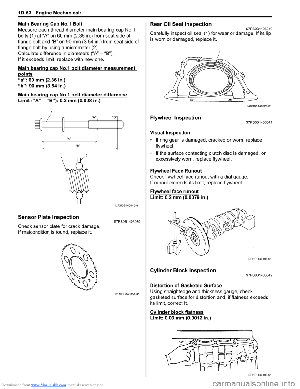
Main Bearing Cap No.1 Bolt
Measure each thread diameter main bearing cap No.1
bolts (1) at “A” on 60 mm (2.36 in.) from seat side of
flange bolt and “B” on 90 mm (3.54 in.) from seat side of
flange bolt by using a micrometer (2).
Calculate difference in diameters (“A” – “B”).
If it exceeds limit, replace with new one.
Main bearing cap No.1 bolt diameter measurement
points
“a”: 60 mm (2.36 in.)
“b”: 90 mm (3.54 in.)
Main bearing cap No.1 bolt diameter difference
Limit (“A” – “B”): 0.2 mm (0.008 in.)
Sensor Plate InspectionS7RS0B1406039
Check sensor plate for crack damage.
If malcondition is found, replace it.
Rear Oil Seal InspectionS7RS0B1406040
Carefully inspect oil seal (1) for wear or damage. If its lip
is worn or damaged, replace it.
Flywheel InspectionS7RS0B1406041
Visual Inspection
• If ring gear is damaged, cracked or worn, replace flywheel.
• If the surface contacting cl utch disc is damaged, or
excessively worn, replace flywheel.
Flywheel Face Runout
Check flywheel face runout with a dial gauge.
If runout exceeds its limit, replace flywheel.
Flywheel face runout
Limit: 0.2 mm (0.0079 in.)
Cylinder Block InspectionS7RS0B1406042
Distortion of Gasketed Surface
Using straightedge and thickness gauge, check
gasketed surface for distortion and, if flatness exceeds
its limit, correct It.
Cylinder block flatness
Limit: 0.03 mm (0.0012 in.)
“A”
“a” “b” “B”
1
1
2
I2RH0B140145-01
I2RH0B140151-01
I4RS0A140020-01
I2RH01140198-01
I2RH01140199-01
Page 349 of 1496
Downloaded from www.Manualslib.com manuals search engine Engine Mechanical: 1D-64
Honing or Reboring Cylinders1) When any cylinder needs reboring, all other cylinders must also be rebored at the same time.
2) Select oversized piston according to amount of cylinder wear.
Oversize piston specification
Oversize 0.50: 78.453 – 78.468 mm (3.0887 –
3.0893 in.)
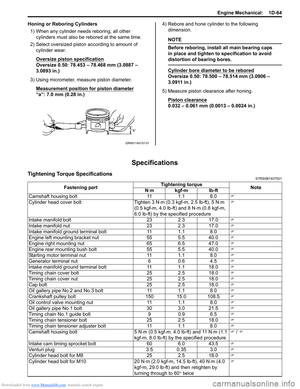
3) Using micrometer, measure piston diameter. Measurement position for piston diameter
“a”: 7.0 mm (0.28 in.) 4) Rebore and hone cylinder to the following
dimension.
NOTE
Before reboring, install all main bearing caps
in place and tighten to specification to avoid
distortion of bearing bores.
Cylinder bore diameter to be rebored
Oversize 0.50: 78.500 – 78.514 mm (3.0906 –
3.0911 in.)
5) Measure piston clearance after honing. Piston clearance
0.032 – 0.061 mm (0.0013 – 0.0024 in.)
Specifications
Tightening Torque SpecificationsS7RS0B1407001
I2RH01140157-01
Fastening part Tightening torque
Note
N ⋅mkgf-mlb-ft
Camshaft housing bolt 11 1.1 8.0 �)
Cylinder head cover bolt Tighten 3 N ⋅m (0.3 kgf-m, 2.5 lb-ft), 5 N ⋅m
(0.5 kgf-m, 4.0 lb-ft) and 8 N ⋅m (0.8 kgf-m,
6.0 lb-ft) by the specified procedure �)
Intake manifold bolt 23 2.3 17.0 �)
Intake manifold nut 23 2.3 17.0 �)
Intake manifold ground terminal bolt 11 1.1 8.0 �)
Engine left mounting bracket nut 55 5.5 40.0 �)
Engine right mounting nut 65 6.5 47.0 �)
Engine rear mounting bush bolt 55 5.5 40.0 �)
Starting motor terminal nut 11 1.1 8.0 �)
Generator terminal nut 6 0.6 4.5 �)
Intake manifold ground terminal bolt 11 1.1 18.0 �)
Timing chain cover bolt 25 2.5 18.0 �)
Timing chain cover nut 25 2.5 18.0 �)
Cap bolt 25 2.5 18.0 �)
Oil gallery pipe No.2 and No.3 bolt 11 1.1 8.0 �)
Crankshaft pulley bolt 150 15.0 108.5 �)
Oil control valve mounting nut 11 1.1 8.0 �)
Oil gallery pipe No.1 bolt 30 3.0 21.5 �)
Timing chain No.1 guide bolt 9 0.9 6.5 �)
Timing chain tensioner bolt 25 2.5 18.0 �)
Timing chain tensioner adjuster bolt 11 1.1 8.0 �)
Camshaft housing bolt 5 N ⋅m (0.5 kgf-m, 4.0 lb-ft) and 11 N ⋅m (1.1
kgf-m, 8.0 lb-ft) by the specified procedure �)
/ �)
Intake cam timing sprocket bolt 60 6.0 43.5 �)
Venturi plug 3.5 0.35 3.0 �)
Cylinder head bolt for M8 25 2.5 18.0 �)
Cylinder head bolt for M10 20 N ⋅m (2.0 kgf-m, 14.5 lb-ft), 40 N ⋅m (4.0
kgf-m, 29.0 lb-ft) and then retighten by
turning through to 60 ° twice �)
Page 351 of 1496
Downloaded from www.Manualslib.com manuals search engine Engine Mechanical: 1D-66
Special Tools and Equipment
Recommended Service MaterialS7RS0B1408001
NOTE
Required service material is also described in the following.
“Timing Chain Cover Components”
“Timing Chain and Chain Tensioner Components”
“Camshaft, Tappet and Shim Components”
“Valves and Cylinder Head Components”
“Pistons, Piston Rings, Connecting Rods and Cylinders Components”
“Main Bearings, Crankshaft and Cylinder Block Components”
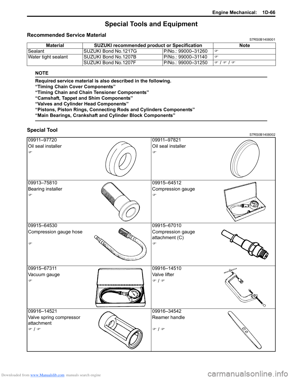
Special ToolS7RS0B1408002
Material SUZUKI recommended product or Specification Note
Sealant SUZUKI Bond No.1217G P/No.: 99000–31260�)
Water tight sealant SUZUKI Bond No.1207B P/No.: 99000–31140�)
SUZUKI Bond No.1207F P/No.: 99000–31250�) / �) / �)
09911–97720 09911–97821
Oil seal installer Oil seal installer
�)�)
09913–75810 09915–64512
Bearing installer Compression gauge
�)�)
09915–64530 09915–67010
Compression gauge hose Compression gauge
attachment (C)
�)�)
09915–67311 09916–14510
Vacuum gauge Valve lifter
�)�) / �)
09916–14521 09916–34542
Valve spring compressor
attachment Reamer handle
�) / �)�) / �)