Page 534 of 1496
Downloaded from www.Manualslib.com manuals search engine 4C-10 Rear Brakes:
• Using micrometer, measure thickness of brake disc.If limit value is exceeded, replace brake disc.
Rear brake disc thickness
Standard: 9 mm (0.354 in.)
Limit: 8 mm (0.315 in.)
Specifications
Tightening Torque SpecificationsS7RS0B4307001
NOTE
The specified tightening torque is also described in the following.
“Rear Disc Brake Components”
Reference:
For the tightening torque of fastener not specified in this section, refer to “Fasteners Information in Section 0A”.
I6RS0B431032-01
Fastening part Tightening torque
Note
N ⋅mkgf-mlb-ft
Caliper pin bolt 23 2.3 17 �)
Wheel bolt 85 8.5 61.5 �) / �) / �)
Brake caliper carrier bolt 60 6.0 43.5 �)
Flexible hose joint bolt 23 2.3 17.0 �)
Parking nut 27 2.7 19.5 �)
Brake pipe flare nut 16 1.6 12.0 �)
Caliper carrier bolt 60 6.0 43.5 �)
Page 535 of 1496
Downloaded from www.Manualslib.com manuals search engine Rear Brakes: 4C-11
Special Tools and Equipment
Recommended Service MaterialS7RS0B4308001
NOTE
Required service material is also described in the following.
“Rear Disc Brake Components”
Special ToolS7RS0B4308002
Material SUZUKI recommended product or Specification Note
Thread lock cement Thread Lock Cement Super 1322 P/No.: 99000–32110 �)
09900–2060709900–20701
Dial gauge Magnetic stand
�)�)
09945–16060
Piston installer handle
�) / �) / �)
Page 546 of 1496
Downloaded from www.Manualslib.com manuals search engine 4E-7 ABS:
Component Location
ABS Components LocationS7RS0B4503001
Front Wheel Speed Sensor Components LocationS7RS0B4503002
14
5
3
2 2
2
2
6
6
6
6
7
8
I6RS0C450005-01
1. ABS hydraulic unit / control module assembly
5. EBD warning light (Brake warning light)
2. Wheel speed sensors 6. Wheel speed sensor rings
3. Stop lamp switch 7. Data link connector
4. ABS warning light 8. ECM
[A]
[B]
1 1
2
3
4
1
(a)
(b)
5I6RS0C450016-01
[A]: OK 2. Grommet5. Front wheel bearing
[B]: NG 3. Connector: 25 N⋅m (2.5 kgf-m, 18.0 lb-ft)
1. Front wheel speed sensor 4. Sensor ring: 11 N⋅m (1.1 kgf-m, 8.0 lb-ft)
Page 547 of 1496

Downloaded from www.Manualslib.com manuals search engine ABS: 4E-8
Rear Wheel Speed Sensor Components LocationS7RS0B4503003
Diagnostic Information and Procedures
ABS CheckS7RS0B4504001
Refer to the following items for the details of each step.
12
3
4
[A]
[B]1
1
(a)
(a)
I6RS0C450006-01
[A]: OK
1. Rear wheel speed sensor 3. Connector: 11 N⋅m (1.1 kgf-m, 8.0 lb-ft)
[B]: NG 2. Sensor ring 4. Grommet
StepAction YesNo
1 �) Malfunction analysis
1) Perform “Customer complaint analysis: ”.
2) Perform “Problem symptom confirmation: ”.
3) Perform “DTC check, record and clearance: ” and recheck DTC.
Is there any malfunction DTC? Go to Step 4.
Go to Step 2.
2 �) Driving test
1) Perform “Step 2: Driving Test: ”.
Is trouble symptom identified? Go to Step 3.
Go to Step 6.
3 �) DTC check
1) Perform “DTC Check”.
Is it malfunction code? Go to Step 4.
Go to Step 5.
4 �) ABS check
1) Inspect and repair referring to applicable DTC flow.
Does trouble recur? Go to Step 5.
Go to Step 7.
5 �) Brakes diagnosis
1) Inspect and repair referring to “Brakes Symptom Diagnosis in Section 4A”.
Does trouble recur? Go to Step 3.
Go to Step 7.
Page 568 of 1496

Downloaded from www.Manualslib.com manuals search engine 4E-29 ABS:
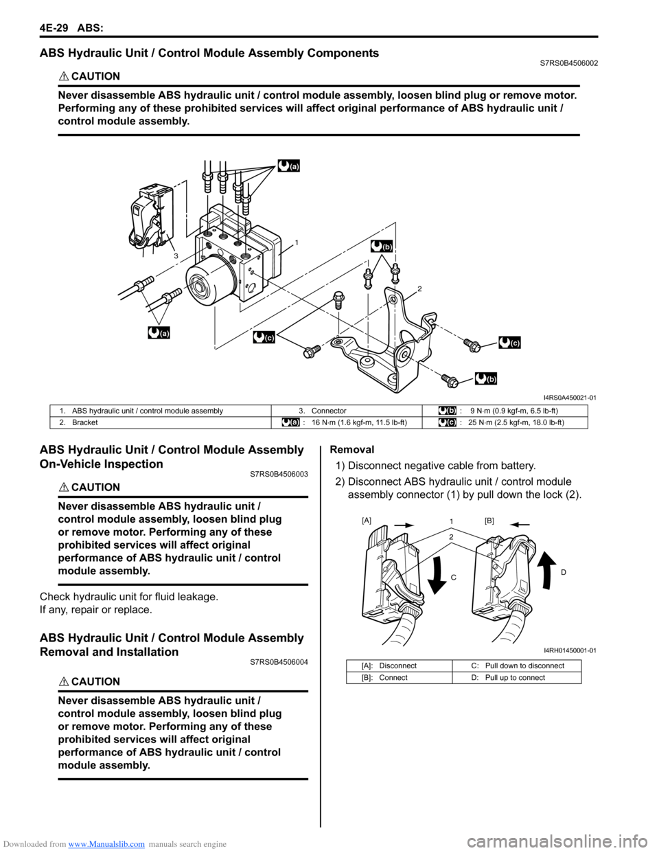
ABS Hydraulic Unit / Control Module Assembly ComponentsS7RS0B4506002
CAUTION!
Never disassemble ABS hydraulic unit / control module assembly, loosen blind plug or remove motor.
Performing any of these prohibited services will affect original performance of ABS hydraulic unit /
control module assembly.
ABS Hydraulic Unit / Control Module Assembly
On-Vehicle Inspection
S7RS0B4506003
CAUTION!
Never disassemble ABS hydraulic unit /
control module assembly, loosen blind plug
or remove motor. Pe rforming any of these
prohibited services wi ll affect original
performance of ABS hydraulic unit / control
module assembly.
Check hydraulic unit for fluid leakage.
If any, repair or replace.
ABS Hydraulic Unit / Control Module Assembly
Removal and Installation
S7RS0B4506004
CAUTION!
Never disassemble ABS hydraulic unit /
control module assembly, loosen blind plug
or remove motor. Pe rforming any of these
prohibited services wi ll affect original
performance of ABS hydraulic unit / control
module assembly.
Removal
1) Disconnect negative cable from battery.
2) Disconnect ABS hydraulic unit / control module assembly connector (1) by pull down the lock (2).
(a)
(a)
(b)
(b)
(c)(c)
1
2
3
I4RS0A450021-01
1. ABS hydraulic unit / control module assembly
3. Connector: 9 N⋅m (0.9 kgf-m, 6.5 lb-ft)
2. Bracket : 16 N⋅m (1.6 kgf-m, 11.5 lb-ft) : 25 N⋅m (2.5 kgf-m, 18.0 lb-ft)
[A]: Disconnect C: Pull down to disconnect
[B]: Connect D: Pull up to connect
21
C D
[A]
[B]
I4RH01450001-01
Page 574 of 1496

Downloaded from www.Manualslib.com manuals search engine 4E-35 ABS:
Specifications
Tightening Torque SpecificationsS7RS0B4507001
NOTE
The specified tightening torque is also described in the following.
“Front Wheel Speed Sensor Components Location”
“Rear Wheel Speed Sensor Components Location”
“ABS Hydraulic Unit / Control Module Assembly Components”
Reference:
For the tightening torque of fastener not specified in this section, refer to “Fasteners Information in Section 0A”.
Special Tools and Equipment
Special ToolS7RS0B4508001
Fastening part Tightening torque
Note
N ⋅mkgf-mlb-ft
Brake pipe flare nut 16 1.6 11.5 �)
ABS hydraulic unit / c ontrol module assembly
bolt 90.9 6.5�)
ABS hydraulic unit / c ontrol module assembly
bracket bolt 25 2.5 18.0�)
Front wheel speed sensor bolt 25 2.5 18.0 �)
Front wheel speed sensor harness clamp bolt 11 1.1 8.0 �)
Rear wheel speed sensor bolt 11 1.1 8.0 �)
Rear wheel speed sensor har ness clamp bolt 11 1.1 8.0 �)
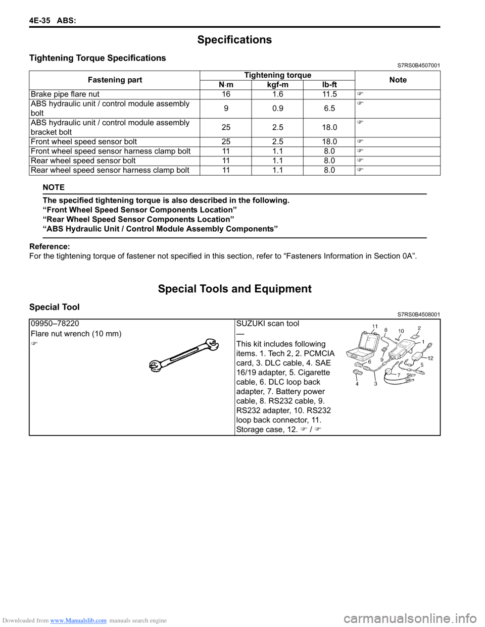
09950–78220SUZUKI scan tool
Flare nut wrench (10 mm) —
�) This kit includes following
items. 1. Tech 2, 2. PCMCIA
card, 3. DLC cable, 4. SAE
16/19 adapter, 5. Cigarette
cable, 6. DLC loop back
adapter, 7. Battery power
cable, 8. RS232 cable, 9.
RS232 adapter, 10. RS232
loop back connector, 11.
Storage case, 12. �) / �)
Page 638 of 1496

Downloaded from www.Manualslib.com manuals search engine 4F-64 Electronic Stability Program:
Removal1) Disconnect negative (–) cable at battery.
2) Remove front console box referring to “Console Box Components in Section 9H”.
3) Disconnect connector from yaw rate / G sensor
assembly.
4) Remove yaw rate / G sens or assembly from sensor
bracket.
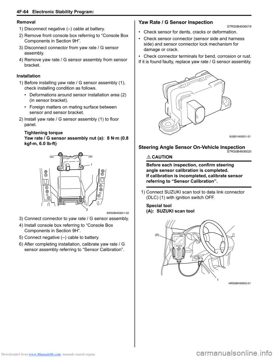
Installation 1) Before installing yaw rate / G sensor assembly (1),
check installing condition as follows.
• Deformations around sensor installation area (2) (in sensor bracket).
• Foreign matters on mating surface between sensor and sensor bracket.
2) Install yaw rate / G sensor assembly (1) to floor panel.
Tightening torque
Yaw rate / G sensor assembly nut (a): 8 N·m (0.8
kgf-m, 6.0 lb-ft)
3) Connect connector to yaw rate / G sensor assembly.
4) Install console box referring to “Console Box Components in Section 9H”.
5) Connect negative (–) cable to battery.
6) After completing installation, calibrate yaw rate / G
sensor assembly referring to “Sensor Calibration”.Yaw Rate / G Sensor InspectionS7RS0B4606019
• Check sensor for dents, cracks or deformation.
• Check sensor connector (sensor side and harness
side) and sensor connector lock mechanism for
damage or crack.
• Check connector terminals for bend, corrosion or rust.
If it is found faulty, replace yaw rate / G sensor assembly.
Steering Angle Sensor On-Vehicle InspectionS7RS0B4606020
CAUTION!
Before each inspection, confirm steering
angle sensor calibration is completed.
If calibration is incompleted, calibrate sensor
referring to “Sensor Calibration”.
1) Connect SUZUKI scan tool to data link connector
(DLC) (1) with ignition switch OFF.
Special tool
(A): SUZUKI scan tool
(a)
1
(a)
2I6RS0B460041-02
I6JB01460031-01
(A)
1
I4RS0B450003-01
Page 639 of 1496

Downloaded from www.Manualslib.com manuals search engine Electronic Stability Program: 4F-65
2) Turn ignition switch to ON position and select menu
“DATA LIST” mode of SUZUKI scan tool.
Refer to scan tool operator's manual for further
derails.
3) Check “Steering angle Sen” under “DATA LIST” of SUZUKI scan tool in th e following steering wheel
conditions.
• Front wheels in straight-ahead position
• Rotate steering wheel a round in clockwise (counter clockwise) from straight-ahead position
If steering angle condition is out of specification,
replace steering angle sensor.
Steering angle Specification
Steering Angle Sensor Removal and InstallationS7RS0B4606021
Refer to “Steering Angle Sensor Removal and
Installation in Section 6B”.
Steering Angle Sensor InspectionS7RS0B4606022
• Check sensor for dents, cracks or deformation.
• Check sensor connector (sensor side and harness
side) and sensor connector lock mechanism for
damage or crack.
• Check connector terminals for bend, corrosion or rust.
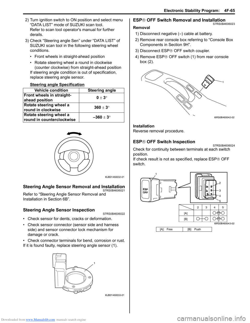
If it is found faulty, replace steering angle sensor (1).
ESP ® OFF Switch Removal and InstallationS7RS0B4606023
Removal
1) Disconnect negative (–) cable at battery.
2) Remove rear console box referring to “Console Box Components in Section 9H”.
3) Disconnect ESP ® OFF switch coupler.
4) Remove ESP ® OFF switch (1) from rear console
box (2).
Installation
Reverse removal procedure.
ESP ® OFF Switch InspectionS7RS0B4606024
Check for continuity between terminals at each switch
position.
If check result is not as specified, replace ESP ® OFF
switch.
Vehicle condition Steering angle
Front wheels in straight-
ahead position 0
± 3 °
Rotate steering wheel a
round in clockwise 360
± 3°
Rotate steering wheel a
round in counterclockwise –360
± 3 °
I6JB01460032-01
1
I6JB01460033-01
[A]: Free [B]: Push
1
I6RS0B460042-02
[A]
[B]2345
2
3
4
1
5
I6RS0B460043-02