Page 169 of 226
 Disconnect the wiring harness connec-
tor from the front fog lamp bulb.
2) Rotate the front fog lamp bulb")
5-25SERVICE AND APPEARANCE CARE
85Z04-03E
Front Fog LampsTo replace a front fog lamp bulb:
1) Disconnect the wiring harness connec-
tor from the front fog lamp bulb.
2) Rotate the front fog lamp bulb counter-
clockwise and remove it.
3) Replace the bulb. See “Replacement
Bulbs” in this section for the proper
bulb.
4) Connect the wiring harness connector
to the front fog lamp bulb.
Center High-Mounted Stop Lamp
(Sedan)To replace a center high-mounted stop
lamp bulb:
1) Open the trunk lid.
2) Remove the two screws which are
recessed on the underside of the hood.
3) Disconnect the wiring harness connec-
tor before removing the lamp housing.
4) Remove the lamp housing.
5) Remove the two screws and the reflec-
tor assembly.
6) Remove the bulb by pulling it straight
out of the bulb socket.
7) Install the new bulb. See “Replacement
Bulbs” in this section for the proper
bulb.
8) Reverse the steps 1 through 5 to rein-
stall the lamp housing.
Center High-Mounted Stop Lamp
(Wagon)To replace a center high-mounted stop
lamp bulb:
1) Open the lift gate.
2) Remove the two screws and the lift gate
trim cover.
3) Remove the bulb socket from the lamp
housing.
4) Remove the bulb by pulling it straight
out of the bulb socket.
5) Install the appropriate bulb into the
socket. See “Replacement Bulbs” in
this section.
6) Replace the lamp housing and trim in
reverse order.
N5U5003A
Bulb Replacement:
Page 170 of 226
 Use a flat screwdriver to pry the lamp
assembly from the lamp assembly
holder.
2) Repl")
5-26
SERVICE AND APPEARANCE CARE
85Z04-03E
Luggage Compartment LampTo replace a luggage compartment lamp
bulb:
1) Use a flat screwdriver to pry the lamp
assembly from the lamp assembly
holder.
2) Replace the bulb. See “Replacement
Bulbs” in this section for the proper
bulb.
3) Reinstall the lamp assembly.
Tail/Stop Lamps, Turn Signal Lamps
and Backup Lamps (Sedan)To replace a tail/stop lamp bulb, a rear turn
signal lamp bulb, or a rear backup lamp
bulb:
1) Open the trunk.
2) Open the trim cover.
3) Remove the bulb socket by turning it
counterclockwise.
4) Remove the bulb from the socket by
pressing the bulb and turning it counter-
clockwise.
5) Install the appropriate bulb into the
socket. See “Replacement Bulbs” in
this section.
6) Replace the bulb socket into the lamp
housing. Turn the bulb socket clockwise
to secure it.
7) Replace the trim cover.
8) Close the trunk.
Tail/Stop Lamps, Turn Signal Lamps
and Backup Lamps (Wagon)To replace a tail/stop lamp bulb, a rear turn
signal lamp bulb, or a rear backup lamp
bulb:
1) Open the lift gate.
2) Remove the two screws shown in the
illustration and the lamp assembly.
3) Remove the bulb socket from the lamp
housing by turning the bulb socket
counterclockwise.
4) Remove the bulb from the socket by
pressing the bulb and turning it counter-
clockwise.
5) Install the appropriate bulb into the
socket. See “Replacement Bulbs” in
this section.
6) Replace the bulb socket into the lamp
housing.
N5U5004A
Bulb Replacement:
Page 171 of 226
 Replace the lamp housing into the vehi-
cle using the two screws removed ear-
lier.
8) Close the lift gate.License Plate LampsTo replace a license plate la")
5-27SERVICE AND APPEARANCE CARE
85Z04-03E
7) Replace the lamp housing into the vehi-
cle using the two screws removed ear-
lier.
8) Close the lift gate.License Plate LampsTo replace a license plate lamp bulb:
1) Remove the two screws shown in the
illustration and the lamp cover.
2) To remove the bulb holder from the
lamp housing, rotate the bulb holder
counterclockwise.
3) Pull the bulb out from the bulb holder.
4) Replace the bulb. See “Replacement
Bulbs” in this section for the proper
bulb.
5) Install the bulb holder into the lamp
housing by rotating the bulb holder
clockwise.
6) Replace the lamp cover.
Rear Side marker LampsTo replace a rear side marker lamp bulb:
1) Insert your hand into the inside of the
rear bumper and hold the socket.
2) Rotate the rear side marker bulb socket
counterclockwise.
3) Pull the rear side marker bulb socket
out of the rear bumper.
4) Pull the old bulb straight out from the
bulb socket.
5) Push a new bulb straight into the
socket.
6) Reverse the steps 1 through 3 to rein-
stall the bulb socket.
Replacement Bulbs
N4U5029B
BulbWattages
x
QuantityBulb
No.
High-Beam
Headlamp55W x 2 H1
Low-Beam
Headlamp55W x 2 H7
Front Turn Signal
Lamp28/8W x 2 2357NA
Front Sidemarker
Lamp5W x 2 168
Stop Lamp/
Tail Lamp27/8W x 4 1157
Rear Turn Signal
Lamp27W x 2 1156NA
Backup Lamp 27W x 2 1156
License Plate
Lamp5W x 2 168
Center
High-Mounted
Stop Lamp5W x 5 168
Rear Sidemarker
Lamp5W x 2 168
Bulb Replacement:
Windshield Wiper Blade Replacement:
Page 172 of 226

5-28
SERVICE AND APPEARANCE CARE
85Z04-03E
Windshield Wiper Blade
ReplacementWindshield wiper blades should be
inspected at least twice a year for wear or
cracking. If the wiper blades become brittle
or damaged, or make streaks when wiping,
replace the wiper blades for optimum driv-
ing visibility. Replacement blades come in
different types and are removed in different
ways.
Here’s how to remove the Shepherd’s
Hook type:
1) Pull the windshield wiper arm away
from the windshield.
2) Press the retaining clip (A) and pull the
wiper blade off the arm.
3) Install a new blade by reversing the
steps 1 and 2.
TiresYour new vehicle comes with high-quality
tires made by a leading tire manufacturer.
If you ever have questions about your tire
warranty and where to obtain service, see
your SUZUKI Warranty booklet for details.
For additional information refer to the tire
manufacturer’s booklet included with your
vehicle’s Owner’s Manual.
Tire Sidewall LabelingUseful information about a tire is molded
into its sidewall. The examples below show
a typical passenger car tire and a spare
tire sidewall.
Passenger Car Tire Example
A. Tire Size
The tire size is a combination of let-
ters and numbers used to define a
particular tire’s width, height, aspect
ratio, construction type and service
description. See the “Tire Size” illus-
WARNING
Poorly maintained and improperly
used tires are dangerous.
Overloading your tires can cause
overheating as a result of too much
friction. You could have an air-out
and a serious accident. See “Load-
ing Your Vehicle” in the Index.
Under inflated tires pose the same
danger as overloaded tires. The
resulting accident could cause
serious injury. Check all tires fre-
quently to maintain the recom-
mended pressure. Tire pressure
should be checked when your tires
are cold.
Overi nflated tires are more likely to
be cut, punctured or broken by a
sudden impact – such as when you
hit a pothole. Keep tires at the rec-
ommended pressure.
(Continued)
WARNING
(Continued)
Worn, old tires can cause acci-
dents. If your tread is badly worn,
or if your tires have been damaged,
replace them.
Tires:
Page 173 of 226

Code
The Department of Transportation
(DOT) code indicates that the tire")
5-29SERVICE AND APPEARANCE CARE
85Z04-03E
tration later in this section for more
detail.
B. Department of Transportation (DOT)
Code
The Department of Transportation
(DOT) code indicates that the tire is in
compliance with the U.S. Department
of Transportation Motor Vehicle
Safety Standards.
C. Tire Identification Number (TIN)
The letters and numbers following the
DOT code are the Tire Identification
Number (TIN). The TIN shows the
manufacturer and plant code, tire size
and the date the tire was manufac-
tured. The TIN is molded on to both
sides of the tire, although only one
side may have the date of manufac-
ture.
D. Tire Ply Material
The type of cord and number of plies
in the sidewall and under the tread.
E. Uniform Tire Quality Grading (UTQG)
Tire manufacturers are required to
grade tires based on three perfor-
mance factors: treadwear, traction
and temperature resistance.
F. Maximum Cold Inflation Load Limit
Maximum load that can be carried
and the maximum pressure needed to
support that load.
G. Load Index and Speed Rating
The two- or three-digit number is the
tire’s load index, the maximum load a
tire can carry at the speed indicated
by its speed symbol at the maximuminflation pressure. The higher the
number is, the greater the load carry-
ing capacity. The letter symbol
denotes the speed at which a tire is
designed to be driven for extended
periods of time. (Ratings are listed
below.)
*The letters ZR may be used on tires with a
maximum speed capability over 149 mph
and will always be used on tires with a
maximum speed capability over 186 mph.Compact Spare Tire Example
A. Temporary Use Only Marking
The compact spare tire should not be
driven at speeds over 50 mph (80 km/
h). The compact spare tire is for
emergency use when a regular road
tire has lost air and gone flat. See
“Compact Spare Tire” and “If a Tire
Goes Flat” in this section.
B. Tire Ply Material
The type of cord and number of plies
in the sidewall and under the tread.
C. Tire Identification Number (TIN)
The Tire Identification Number (TIN)
shows the manufacturer and plant
code, tire size, and date the tire was
manufactured. The TIN is molded
onto both sides of the tire, although
only one side may have the date of
manufacture.
D. Maximum Cold Inflation Load Limit
Maximum load that can be carried Letter Rating Speed Rating
Q 99 mph
R106 mph
S112 mph
T118 mph
U124 mph
H130 mph
V149 mph
W 168 mph*
Y 186 mph*
Tires:
Page 174 of 226

5-30
SERVICE AND APPEARANCE CARE
85Z04-03E
and the maximum pressure needed to
support that load. See “Compact
Spare Tire” in this section and “Load-
ing Your Vehicle” in section 4.
E. Tire Inflation Pressure
The temporary use tire or compact
spare tire should be inflated to 60 psi
(420 kPa). For more information on
tire pressure and inflation, see “Tire
Inflation Pressure” in this section.
F. T i r e S i z e
A combination of letters and numbers
defining a tire’s width, height, aspect
ratio, construction type and service
description. The letter “T” as the first
character in the tire size means the
tire is for temporary use only.
Tire Size
The following illustration shows an exam-
ple of a typical passenger car tire size.
A. Tire Type
This letter code indicates the primary
intended use of the tire. The “P” as
the first character in the tire size
means a passenger vehicle tire engi-
neered to standards set by the U.S.
Tire and Rim Association.
B. Tire Width
The three-digit number indicates the
tire section width in millimeters from
sidewall to sidewall.
C. Aspect Ratio
A two-digit number that indicates the
tire height-to-width measurements.
For example, if the tire size aspect
ratio is “70”, as shown in item “C” of
the illustration, it would mean that thetire’s sidewall is 70% as high as it is
wide.
D. Construction Code
A letter code is used to indicate the
type of ply construction in the tire. The
letter “R” means radial ply construc-
tion, the letter “D” means diagonal or
bias ply construction; and the letter
“B” means belted-bias ply construc-
tion.
E. Rim Diameter
Diameter of the wheel in inches.
F. Service Description
These characters represent the load
range and the speed rating of a tire.
The load range represents the load
carrying capacity a tire is certified to
carry. The speed rating is the maxi-
mum speed a tire is certified to carry
a load. Speed ratings range from “A”
to “Z”.
WARNING
Your SUZUKI is equipped with tires
which are all the same type and size.
This is important to ensure proper
steering and handling of the vehicle.
Never mix tires of different size or
type on the four wheels of your vehi-
cle. Mixing tires could cause you to
lose control while driving which may
lead to an accident. The size and type
of tires used should be only those
approved by SUZUKI Motor Corpora-
tion as standard or optional equip-
ment for your vehicle.
Tires:
Page 175 of 226

5-31SERVICE AND APPEARANCE CARE
85Z04-03E
Glossary of Tire TerminologyAir Pressure:
The amount of air inside the tire pressing
outward on each square inch of the tire. Air
pressure is expressed in pounds per
square inch (psi) or kilopascal (kPa).
Accessory Weight:
This means the combined weight of
optional accessories. Some examples of
optional accessories are automatic trans-
mission, power steering, power brakes,
power windows, power seats, and air con-
ditioning.
Aspect Ratio:
The relationship of a tire’s height to its
width.
Belt:
A rubber coated layer of cords that is
located between the plies and the tread.
Cords may be made from steel or other
reinforcing materials.
Bead:
The tire bead contains steel wires wrapped
by steel cords that hold the tire onto the
rim.
Bias Ply Tire:
A pneumatic tire in which the plies are laid
at alternate angles less than 90 degrees to
the centerline of the tread.Cold Inflation Pressure:
The amount of air pressure in a tire, mea-
sured in pounds per square inch (psi)
before a tire has built up heat from driving.
Curb Weight:
This means the weight of a motor vehicle
with standard and optional equipment
including the maximum capacity of fuel, oil
and coolant, but without passengers and
cargo.
DOT Markings:
A code molded into the sidewall of a tire
signifying that the tire is in compliance with
the U.S. Department of Transportation
motor vehicle safety standards. The DOT
code includes the Tire Identification Num-
ber (TIN), an alphanumeric designator
which can also identify the tire manufac-
turer, production plant, brand and date of
production.
GVWR:
Gross Vehicle Weight Rating.
This is the maximum permissible overall
weight of the fully loaded vehicle (including
all occupants, accessories and cargo).
GAWR:
Gross Axle Weight Rating.
This is the maximum permissible weight on
an individual axle.
Intended Outboard Sidewall:
The side of an asymmetrical tire that must
always face outward when mounted on a
vehicle.Kilopascal (kPa):
The metric unit for air pressure. There are
6.9 kPa’s to one psi.
Light Truck (LT-Metric) Tire:
A tire used on light duty trucks and some
multipurpose passenger vehicles.
Load Index:
An assigned number ranging from 1 to 279
that corresponds to the load carrying
capacity of a tire.
Maximum Inflation Pressure:
The maximum air pressure to which a cold
tire may be inflated. The maximum air
pressure is molded onto the sidewall.
Maximum Load Rating:
The load rating for a tire at the maximum
permissible inflation pressure for that tire.
Maximum Loaded Vehicle Weight:
The sum of curb weight; accessory weight;
vehicle capacity weight; and production
options weight.
Normal Occupant Weight:
The number of occupants a vehicle is
designed to seat multiplied by 150 pounds
(68 kg).
Occupant Distribution:
Distribution of occupants in a vehicle as
specified in the third column of Table 1
(shown below).
Outward Facing Sidewall:
The side of a asymmetrical tire that has a
particular side that faces outward when
Tires:
Page 176 of 226

5-32
SERVICE AND APPEARANCE CARE
85Z04-03E
mounted on a vehicle. The side of the tire
that contains a whitewall, bears white let-
tering or bears manufacturer, brand and or
model name molding that is higher or
deeper than the same moldings on the
other sidewall of the tire.
Passenger (P-Metric) Tire:
A tire used on passenger cars and some
light duty trucks and multipurpose vehicles.
Production Options Weight:
The combined weight of those installed
regular production options weighing over
2.3 kilograms in excess of those standard
items which they replace, not previously
considered in curb weight or accessory
weight, including heavy duty brakes, ride
levelers, roof rack, heavy duty battery, and
special trim.
Recommended Inflation Pressure:
Vehicle manufacturer’s recommended tire
inflation pressure shown on the tire plac-
ard.
Radial Ply Tire:
A pneumatic tire in which the ply cords that
extend to the beads are laid at 90 degrees
to the centerline of the tread.
Rim:
A metal support for a tire and upon which
the tire beads are seated.
Sidewall:
The portion of a tire between the tread and
the bead.Speed Rating:
An alphanumeric code assigned to a tire
indicating the maximum speed at which a
tire can operate.
Tr a c t i o n :
The friction between the tire and the road
surface. The amount of grip provided.
Tr e a d :
The portion of a tire that comes into con-
tact with the road.
Tread wear Indicators:
Narrow bands, sometimes called “wear
bars,” that show across the tread of a tire
when only 2/32 inch of tread remains.
UTQGS:
Uniform Tire Quality Grading Standards, a
tire information system that provides con-
sumers with ratings for a tire’s traction,
temperature and tread wear. Ratings are
determined by tire manufacturers using
government testing procedures. The rat-
ings are molded into the sidewall of the
tire.
Vehicle Capacity Weight:
The number of designated seating posi-
tions multiplied by 150 lbs (68 kg) plus the
rated cargo load.
Vehicle Maximum Load on the Tire:
The load on an individual tire that is deter-
mined by distributing to each axle its share
of the maximum loaded vehicle weight and
dividing by two.Vehicle Normal Load on the Tire:
The load on an individual tire that is deter-
mined by distributing to each axle its share
of the curb weight, accessory weight, and
normal occupant weight (distributed in
accordance with Table 1 shown below) and
dividing by 2.
TABLE 1 – Occupant Loading and Dis-
tribution For Vehicle Normal Load For
Various Designated Seating Capacities
Vehicle Placard:
A label permanently attached to a vehicle
showing the original equipment tire size
and recommended inflation pressure.
Designated
seating capac-
ity, number of
occupantsVehicle nor-
mal load, num-
ber of
occupantsOccupant
distribution in
a normally
loaded vehicle
2 through 4 2 2 in front
5 through 10 32 in front, 1 in
second seat
Tires:
 1
1 2
2 3
3 4
4 5
5 6
6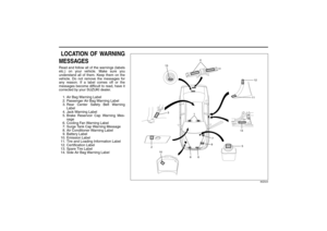 7
7 8
8 9
9 10
10 11
11 12
12 13
13 14
14 15
15 16
16 17
17 18
18 19
19 20
20 21
21 22
22 23
23 24
24 25
25 26
26 27
27 28
28 29
29 30
30 31
31 32
32 33
33 34
34 35
35 36
36 37
37 38
38 39
39 40
40 41
41 42
42 43
43 44
44 45
45 46
46 47
47 48
48 49
49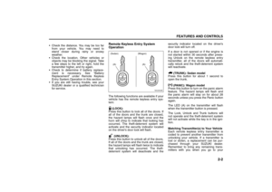 50
50 51
51 52
52 53
53 54
54 55
55 56
56 57
57 58
58 59
59 60
60 61
61 62
62 63
63 64
64 65
65 66
66 67
67 68
68 69
69 70
70 71
71 72
72 73
73 74
74 75
75 76
76 77
77 78
78 79
79 80
80 81
81 82
82 83
83 84
84 85
85 86
86 87
87 88
88 89
89 90
90 91
91 92
92 93
93 94
94 95
95 96
96 97
97 98
98 99
99 100
100 101
101 102
102 103
103 104
104 105
105 106
106 107
107 108
108 109
109 110
110 111
111 112
112 113
113 114
114 115
115 116
116 117
117 118
118 119
119 120
120 121
121 122
122 123
123 124
124 125
125 126
126 127
127 128
128 129
129 130
130 131
131 132
132 133
133 134
134 135
135 136
136 137
137 138
138 139
139 140
140 141
141 142
142 143
143 144
144 145
145 146
146 147
147 148
148 149
149 150
150 151
151 152
152 153
153 154
154 155
155 156
156 157
157 158
158 159
159 160
160 161
161 162
162 163
163 164
164 165
165 166
166 167
167 168
168 169
169 170
170 171
171 172
172 173
173 174
174 175
175 176
176 177
177 178
178 179
179 180
180 181
181 182
182 183
183 184
184 185
185 186
186 187
187 188
188 189
189 190
190 191
191 192
192 193
193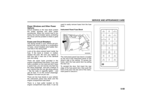 194
194 195
195 196
196 197
197 198
198 199
199 200
200 201
201 202
202 203
203 204
204 205
205 206
206 207
207 208
208 209
209 210
210 211
211 212
212 213
213 214
214 215
215 216
216 217
217 218
218 219
219 220
220 221
221 222
222 223
223 224
224 225
225