2008 SUBARU OUTBACK ECU
[x] Cancel search: ECUPage 157 of 444

3-38Instruments and controls
SUBARU dealer as soon as possible. . The light does not go out even after the
lapse of several minutes (the engine has
warmed up) after the engine has started. & Security indicator light
This indicator light shows the status of the
alarm system. It also indicates operation
of the immobilizer system. !Alarm system
It blinks to show the driver the operational
status of the alarm system. For detailed
information, refer to the “Alarm system ”
section in chapter 2. ! Immobilizer system
This light blinks approximately 60 seconds
after the ignition switch is turned from“ ON ”position to the “Acc ”or “LOCK ”
position or immediately after the key is
pulled out. (Refer to the “Door locks ”
section in chapter 2.)
If the indicator light does not flash, it may
indicate that immobilizer system may be
faulty. Contact your nearest SUBARU
dealer immediately.
In the event that an unauthorized key (for
example, an unauthorized duplicate) is
used, the security indicator light comeson. &
SPORT mode indicator
light (4-speed AT mod-
els) (if equipped)
This light comes on when the ignition
switch is turned to the “ON ”position and
goes out after the engine has started.
When the selector lever is moved to the
manual gate, the SPORT mode is se-
lected and the indicator light comes on.
(Refer to the “Automatic transmission –4-
speed ”section in chapter 7.)
& Shift-up indicator light
(MT models) (if equipped)
When the ignition switch is turned to the “ON ”position, the indicator light comes on
for 3 seconds, and then turns off. While
selecting the Intelligent (I) mode of SI-
DRIVE, this indicator light comes on and
informs the upshift timing to the driver for
fuel-efficient driving. &
S# PREP indicator light
(if equipped)1) S# PREP indicator light
When the engine is not warmed up
sufficiently, the S# PREP indicator light
turns on. While this indicator light is on,
the SI-DRIVE mode cannot be changed to
the Sport Sharp (S#) mode. For details
about the SI-DRIVE mode, refer to the “SI-
DRIVE (Except 2.5-liter non-Turbo mod-els) ”section in chapter 7.
Page 177 of 444

3-58Instruments and controls
“LOCK ”position. If defrosting or defogging
is desired when you restart your vehicle,
you have to push the button to turn it onagain. NOTE . While the outside mirror defogger is
operating, the rear window defogger
also operates.. When the rear window defogger has
been set for continuous operation, the
outside mirror defogger also operates
continuously. Refer to the “Rear win-
dow defogger button ”section in this
chapter.
CAUTION
To prevent the battery from being
discharged, do not operate the de-
fogger continuously for any longer
than necessary. Tilt/telescopic steering wheel
WARNING
. Do not adjust the steering wheel
tilt/telescopic position while driv-
ing. This may cause loss of
vehicle control and result in
personal injury.
. If the lever cannot be raised to
the fixed position, adjust the
steering wheel again. It is dan-
gerous to drive without locking
the steering wheel. This may
cause loss of vehicle control
and result in personal injury.
1. Adjust the seat position. Refer to the “
Front seats ”section (chapter 1).
2. Pull the tilt/telescopic lock lever down.
3. Move the steering wheel to the desired level.
4. Pull the lever up to lock the steering
wheel in place.
5. Make sure that the steering wheel is
securely locked by moving it up and down,
and forward and backward.
Page 232 of 444

6-12Interior equipment
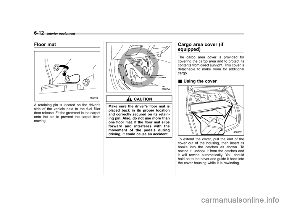
Floor mat
A retaining pin is located on the driver ’s
side of the vehicle next to the fuel filler
door release. Fit the grommet in the carpet
onto the pin to prevent the carpet frommoving.
CAUTION
Make sure the driver ’s floor mat is
placed back in its proper location
and correctly secured on its retain-
ing pin. Also, do not use more than
one floor mat. If the floor mat slips
forward and interferes with the
movement of the pedals during
driving, it could cause an accident. Cargo area cover (if
equipped)
The cargo area cover is provided for
covering the cargo area and to protect its
contents from direct sunlight. This cover is
detachable to make room for additionalcargo. &
Using the cover
To extend the cover, pull the end of the
cover out of the housing, then insert its
hooks into the catches as shown. To
rewind it, unhook it from the catches and
it will rewind automatically. You should
hold on to the cover and guide it back into
the cover housing while it is rewinding.
Page 236 of 444

6-16Interior equipment
Convenient tie-down hooks
(if equipped)
CAUTION
The convenient tie-down hooks are
designed only for securing light
cargo. Never try to secure cargo
that exceeds the capacity of the
hooks. The maximum load capacity
is 44 lbs (20 kg) per hook.
The cargo area is equipped with four tie-
down hooks so that cargo can be secured
with a luggage net or ropes.
When using the tie-down hooks, turn them
down out of the storing recesses. When
not in use, put the hooks up into the storing recesses.
Under-floor storage compart- ment
The subfloor storage compartment is
located under the floor of the trunk or
cargo area and can be used to store small
items. To open the lid, pull the tab or
handle up. NOTE
When storing a flat tire, put the sub-
floor storage in the trunk or cargo area.
CAUTION
. Always keep the lid of the sub-
floor storage compartment
closed while driving to reduce
the risk of injury in the event of
sudden stop or an accident.
. Do not store spray cans, contain-
ers with flammable or corrosive
liquids or any other dangerous
items in the subfloor storagecompartment.
Page 237 of 444

Sedan
Station wagon
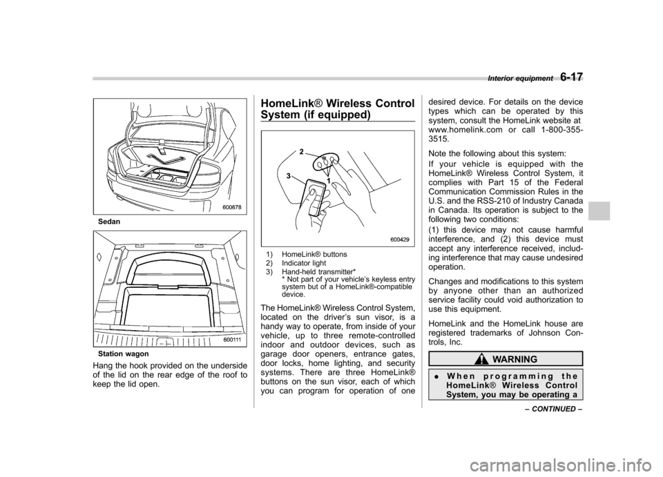
Hang the hook provided on the underside
of the lid on the rear edge of the roof to
keep the lid open. HomeLink
®Wireless Control
System (if equipped)
1) HomeLink® buttons
2) Indicator light
3) Hand-held transmitter* * Not part of your vehicle ’s keyless entry
system but of a HomeLink®-compatible device.
The HomeLink® Wireless Control System,
located on the driver ’s sun visor, is a
handy way to operate, from inside of your
vehicle, up to three remote-controlled
indoor and outdoor devices, such as
garage door openers, entrance gates,
door locks, home lighting, and security
systems. There are three HomeLink®
buttons on the sun visor, each of which
you can program for operation of one desired device. For details on the device
types which can be operated by this
system, consult the HomeLink website at
www.homelink.com or call 1-800-355-3515.
Note the following about this system:
If your vehicle is equipped with the
HomeLink® Wireless Control System, it
complies with Part 15 of the Federal
Communication Commission Rules in the
U.S. and the RSS-210 of Industry Canada
in Canada. Its operation is subject to the
following two conditions:
(1) this device may not cause harmful
interference, and (2) this device must
accept any interference received, includ-
ing interference that may cause undesiredoperation.
Changes and modifications to this system
by anyone other than an authorized
service facility could void authorization to
use this equipment.
HomeLink and the HomeLink house are
registered trademarks of Johnson Con-
trols, Inc.
WARNING
. When programming the
HomeLink ®Wireless Control
System, you may be operating a Interior equipment
6-17
– CONTINUED –
Page 241 of 444

opener by pressing the programmed
HomeLink® button. &Programming other devices
To program other devices such as door
locks, home lighting and security systems,
contact HomeLink at www.homelink.com
or call 1-800-355-3515. & Operating the HomeLink ®
Wireless Control System
Once programmed, the HomeLink® Wire-
less Control System can be used to
remote-control the devices to which its
buttons are programmed. To activate a
device, simply press the appropriate but-
ton. The indicator light illuminates, indicat-
ing that the signal is being transmitted. & Reprogramming a single HomeLink ®button
1. Press and hold the HomeLink® button
you wish to reprogram. DO NOT release
the button until step 4 has been com-pleted.
2. When the HomeLink® indicator light
begins to flash slowly (after 20 seconds),
position the hand-held transmitter of the
device for which you wish to program the
button at 1 to 3 inches (25 to 76 mm) away
from the HomeLink® button surface. 3. Press and hold the hand-held trans-
mitter button. The HomeLink® indicator
light will flash, first slowly and then rapidly.
4. When the indicator light begins to flash
rapidly, release both buttons.
The programming for the previous device
is now erased and the new device can be
operated by pushing the HomeLink®button.
& Erasing HomeLink ®button
memory
NOTE . Performing this procedure erases
the memory of all the preprogrammed
buttons simultaneously. The memory
of individual buttons cannot be erased.. It is recommended that upon the
sale of the vehicle, the memory of all
programmed HomeLink ®buttons be
erased for security purposes.
1. Press and hold the two outside buttons
until the indicator light begins to flash
(after 20 seconds).
2. Release both buttons. & In case a problem occurs
If you cannot activate a device using the
corresponding HomeLink® button after
programming, contact HomeLink at www.homelink.com or call 1-800-355-
3515 for assistance.
Interior equipment
6-21
Page 252 of 444

Remote engine start system
(dealer option)
WARNING
. Do not remote start a vehicle in
an enclosed environment (e.g.
closed garage). Prolonged opera-
tion of a motor vehicle in an
enclosed environment can cause
a harmful build-up of Carbon
Monoxide. Carbon Monoxide is
harmful to your health. Exposure
to high levels of Carbon Monox-
ide can cause headaches, dizzi-
ness or in extreme cases uncon-
sciousness and/or death.
. Before performing any servicing
of the vehicle, temporarily place
the remote engine start system in
service mode to prevent the
system from unexpectedly start-
ing the engine.
& Starting your vehicle
The remote control start system is acti-
vated by pressing the “
”button twice
within 3 seconds on your remote control
transmitter. The system will check certain
pre-conditions before starting, and if all
safety parameters are correct, the engine
will start within 5 seconds. While the
vehicle is operating via remote engine
start, the vehicle ’s power window features
will be disabled. Also, the system has a
timer and will shut down after 15 minutes if
you do not operate the vehicle. Press and
hold the “
”button for 2 seconds again to
turn the vehicle off. If the vehicle ’s starter
cranks but does not start or starts and
stalls, the remote engine start system will
power off then attempt to start the vehicle an additional four times. If the vehicle fails
to start after the additional attempts, the
remote engine start system will abort and
return to a non activated state.
& Remote start safety features
For safety and security reasons, the
system will fail to start and beep the horn
twice or shut down the engine during
remote start operation if any of the
following occur: . The brake pedal is pressed before the
vehicle ignition switch is turned “on ”
. The key was already in the ignition
switch. The engine hood is opened
. The vehicle ’s engine idle speed has
reached a level over 3,000 RPM. The alarm is triggered by opening a
door or the rear gate. NOTE . The security indicator light on the
dashboard will stop flashing while
under remote engine start operation,
but the vehicle is still protected.. If the vehicle is entered during
remote engine star t operation, the
system will not record entry in the
alarm history. Starting and operating
7-11
– CONTINUED –
Page 259 of 444

7-18Starting and operating
Automatic transmission –4-
speed
The automatic transmission is electroni-
cally controlled and provides 4 forward
speeds and 1 reverse speed. Also, it has a
manual mode and a SPORT mode.
WARNING
Do not shift from the “P ” or “N ”
position into the “D ” or “R ” position
while depressing the accelerator
pedal. This may cause the vehicle
to jump forward or backward.
CAUTION
. Shift into the “P ” or “R ” position
only after the vehicle is comple-
tely stopped. Shifting while the
vehicle is moving may cause
damage to the transmission.
. Do not race the engine for more
than 5 seconds in any position
except the “N ” or “P ” position
when the brake is set or when
chocks are used in the wheels.
This may cause the automatic
transmission fluid to overheat.
. Avoid shifting from one of the forward driving positions into the“
R ” position or vice versa until
the vehicle has completely
stopped. Such shifting may
cause damage to the transmis-sion.
. When parking the vehicle, first
securely apply the parking brake
and then place the selector lever
in the “P ” position. Avoid parking
for a long time with the selector
lever in any other position as
doing so could result in a dead
battery.
NOTE . When the engine coolant tempera-
ture is still low, your vehicle ’s auto-
matic transmission will up-shift at high-
er engine speeds than when the cool-
ant temperature is sufficiently high in
order to shorten the warm-up time and
improve driveability. The gearshift tim-
ing will automatically shift to the nor-
mal timing after the engine has warmedup.. Immediately after ATF (automatic
transmission fluid) is replaced, you
may feel that the automatic transmis-
sion operation is somewhat unusual.
This results from invalidation of data which the on-board computer has
collected and stored in memory to
allow the transmission to shift at the
most appropriate times for the current
condition of your vehicle. Optimized
shifting will be restored as the vehicle
continues to be driven for a while. &
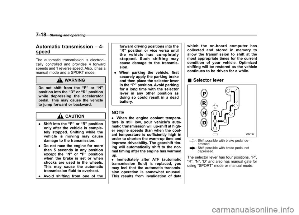
Selector lever
: Shift possible with brake pedal de-
pressed
: Shift possible with brake pedal not
depressed
The selector lever has four positions, “P ”,
“ R ”, “N ”, “D ”and also has manual gate for
using “SPORT ”mode or manual mode.