2008 SUBARU OUTBACK tow
[x] Cancel search: towPage 118 of 444

!Tilting moonroof
1) Open
2) Close
To tilt up the front moonroof, open the sun
shade and pull the switch to the “OPEN ”
side.
To tilt down the front moonroof, push the
switch to the “CLOSE ”side, then quickly
release it. If you wish to stop the tilting-
down motion of the front moonroof part-
way, either pull the switch to the “OPEN ”
side or push it to the “CLOSE ”side. !
Sliding moonroof1) Open
2) Close
To fully open the rear moonroof, tilt up the
front moonroof then pull the switch to the“ OPEN ”side and quickly release it. The
rear moonroof will stop at a position
approximately 6.7 in (17 cm) from its fully
closed position.
After confirming safety, pull the switch to the “OPEN ”side again and quickly release
it. The rear moonroof will open to its fully
open position. To stop the rear moonroof
at some selected mid-way point while it is
moving toward its fully open position,
momentarily push the switch to the“ CLOSE ”or “OPEN ”side.
To fully close the rear moonroof, push the switch to the
“CLOSE ”side then quickly
release it.
The rear moonroof will stop at a position
approximately 5.9 in (15 cm) before its
fully closed position. After confirming
safety, pull the switch to the “CLOSE ”
side again and quickly release it. The rear
moonroof will fully close. The front moon-
roof can then be fully closed. ! Anti-entrapment function
When the moonroof senses an object
trapped between its glass and during
closure, it automatically moves back by
5.9 in (15 cm) from that point and then
stops. The anti-entrapment function may
also be activated by a strong shock on the
moonroof even when there is nothingtrapped.
NOTE . For the sake of safety, it is recom-
mended that you avoid driving with the
moonroof fully opened.. Driving with the moonroof fully open
can cause an annoying sound to gen-
erate at high speeds. If such a condi-
tion has been encountered, use the
moonroof at the initial stop position of
6.7 in (17 cm). Keys and doors
2-29
– CONTINUED –
Page 122 of 444

Ignition switch
WARNING
. Never turn the ignition switch to
“ LOCK ”while the vehicle is
being driven or towed because
that will lock the steering wheel,
preventing steering control. And
when the engine is turned off, it
takes a much greater effort than
usual to steer.
. Before leaving the vehicle, al-
ways remove the key from the
ignition switch for safety and
never allow an unattended child
to remain in the vehicle. Failure
to follow this procedure could
result in injury to a child or
others. Children could operate
the power windows, the sunroof
or other controls or even make
the vehicle move.
CAUTION
Do not attach a large key holder or
key case to either key. If it banged
against your knees or hands while
you were driving, it could turn the
ignition switch from the “ON ”posi- tion to the
“Acc ”or “LOCK ”posi-
tion, thereby stopping the engine.
Also, if the key is attached to a
keyholder or to a large bunch of
other keys, centrifugal force may act
on it as the vehicle moves, resulting
in unwanted turning of the ignitionswitch.
The ignition switch has four positions:
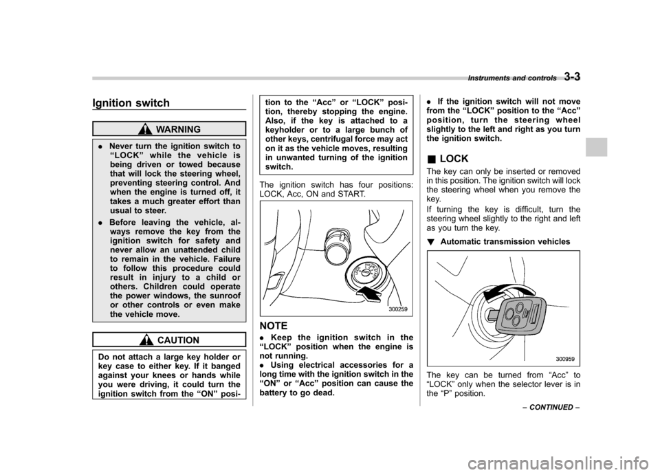
LOCK, Acc, ON and START.
NOTE . Keep the ignition switch in the
“ LOCK ”position when the engine is
not running. . Using electrical accessories for a
long time with the ignition switch in the“ ON ”or “Acc ”position can cause the
battery to go dead. .
If the ignition switch will not move
from the “LOCK ”position to the “Acc ”
position, turn the steering wheel
slightly to the left and right as you turn
the ignition switch. & LOCK
The key can only be inserted or removed
in this position. The ignition switch will lock
the steering wheel when you remove the
key.
If turning the key is difficult, turn the
steering wheel slightly to the right and left
as you turn the key. ! Automatic transmission vehicles
The key can be turned from “Acc ”to
“ LOCK ”only when the selector lever is in
the “P ”position. Instruments and controls
3-3
– CONTINUED –
Page 151 of 444

3-32Instruments and controls
turn off immediately. It may take several
driving trips. If the light does not go out,
take your vehicle to your authorized
SUBARU dealer immediately. !If the light is blinking:
If the light is blinking while driving, an
engine misfire condition has been de-
tected which may damage the emission
control system.
To prevent serious damage to the emis-
sion control system, you should do thefollowing. . Reduce vehicle speed.
. Avoid hard acceleration.
. Avoid steep uphill grades.
. Reduce the amount of cargo, if possi-
ble.. Stop towing a trailer as soon as
possible.
The CHECK ENGINE warning light/mal-
function indicator lamp may stop blinking
and come on steadily after several driving
trips. You should have your vehicle
checked by an authorized SUBARU deal-
er immediately. & Charge warning light
If this light comes on when the engine is
running, it may indicate that the charging
system is not working properly. If the light comes on while driving or does
not go out after the engine starts, stop the
engine at the first safe opportunity and
check the alternator belt. If the belt is
loose, broken or if the belt is in good
condition but the light remains on, contact
your nearest SUBARU dealer immedi-
ately.
& Oil pressure warning light
CAUTION
Do not operate the engine with the
oil pressure warning light on. This
may cause serious engine damage.
If this light comes on when the engine is
running, it may indicate that the engine oil
pressure is low and the lubricating system
is not working properly.
If the light comes on while driving or does
not go out after the engine starts, stop the
engine at the first safe opportunity and
check the engine oil level. If the oil level is
low, add oil immediately. If the engine oil is
at the proper level but the light remains on,
contact your nearest SUBARU dealer
immediately. &
AT OIL TEMPerature
warning light (AT mod- els)
The AT oil temperature warning light
comes on when the ignition switch is
turned to the “ON ”position and goes out
after approximately 2 seconds.
If this light comes on when the engine is
running, it may indicate that the automatic
transmission fluid temperature is too hot.
If the light comes on while driving,
immediately stop the vehicle in a safe
place and let the engine idle until the
warning light goes off. ! Automatic transmission control
system warning
If the light flashes after the engine starts, it
may indicate that the automatic transmis-
sion control system is not working prop-
erly. Contact your nearest SUBARU deal-
er for service immediately. & Low tire pressure
warning light (U.S.-spec.models)
When the ignition switch is turned to the “ON ”position, the low tire pressure warn-
ing light will come on for approximately 2
seconds to check that the tire pressure
monitoring system (TPMS) is functioning
Page 154 of 444

&Brake system
warning light
WARNING
. Driving with the brake system
warning light on is dangerous.
This indicates your brake system
may not be working properly. If
the light remains on, have the
brakes inspected by a SUBARU
dealer immediately.
. If at all in doubt about whether
the brakes are operating prop-
erly, do not drive the vehicle.
Have your vehicle towed to the
nearest SUBARU dealer for re-
pair.
This light has the following three functions: ! Parking brake warning
The light comes on with the parking brake
applied while the ignition switch is in the“ ON ”position. It goes out when the
parking brake is fully released. ! Brake fluid level warning
This light comes on when the brake fluid
level has dropped to near the “MIN ”level
of the brake fluid reservoir with the ignition
switch in the “ON ”position and with the
parking brake fully released. If the brake system warning light should
come on while driving (with the parking
brake fully released and with the ignition
switch positioned in
“ON ”), it could be an
indication of leaking of brake fluid or worn
brake pads. If this occurs, immediately
stop the vehicle at the nearest safe place
and check the brake fluid level. If the fluid
level is below the “MIN ”mark in the
reservoir, do not drive the vehicle. Have
the vehicle towed to the nearest SUBARU
dealer for repair. ! Electronic Brake Force Distribution
(EBD) system warning
The brake system warning light also
illuminates if a malfunction occurs in the
EBD system. In that event, it comes on
together with the ABS warning light.
The EBD system may be faulty if the
brake system warning light and ABS
warning light illuminate simultaneously
during driving.
Even if the EBD system fails, the conven-
tional braking system will still function.
However, the rear wheels will be more
prone to locking when the brakes are
applied harder than usual and the vehi-cle ’s motion may therefore become some-
what harder to control.
If the brake system warning light and ABS
warning light illuminate simultaneously, take the following steps:
1. Stop the vehicle in the nearest safe,
flat place.
2. Shut down the engine, then restart it.
3. Release the parking brake. If both
warning lights go out, the EBD system
may be faulty.
Drive carefully to the nearest SUBARU
dealer and have the system inspected.
4. If both warning lights come on again
and stay illuminated after the engine has
been restarted, shut down the engine
again, apply the parking brake, and check
the brake fluid level.
5. If the brake fluid level is not below the “
MIN ”mark, the EBD system may be
faulty. Drive carefully to the nearest
SUBARU dealer and have the systeminspected.
6. If the brake fluid level is below the “ MIN ”mark, DO NOT drive the vehicle.
Instead, have the vehicle towed to the
nearest SUBARU dealer for repair.
& Low fuel warning light
The low fuel warning light comes on when
the tank is nearly empty approximately 2.6
US gal (10.0 liters, or 2.2 Imp gal). It only
operates when the ignition switch is in the“ON ”position. Instruments and controls
3-35
– CONTINUED –
Page 165 of 444

3-46Instruments and controls
&Headlights
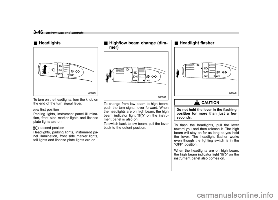
To turn on the headlights, turn the knob on
the end of the turn signal lever.
first position
Parking lights, instrument panel illumina-
tion, front side marker lights and license
plate lights are on.
second position
Headlights, parking lights, instrument pa-
nel illumination, front side marker lights,
tail lights and license plate lights are on. &
High/low beam change (dim- mer)
To change from low beam to high beam,
push the turn signal lever forward. When
the headlights are on high beam, the high
beam indicator light “
”on the instru-
ment panel is also on.
To switch back to low beam, pull the lever
back to the detent position. &
Headlight flasher
CAUTION
Do not hold the lever in the flashing
position for more than just a fewseconds.
To flash the headlights, pull the lever
toward you and then release it. The high
beam will stay on for as long as you hold
the lever. The headlight flasher works
even though the lighting switch is in the“ OFF ”position.
When the headlights are on high beam,
the high beam indicator light “
”on the
instrument panel also comes on.
Page 170 of 444

Sedan
OFF : Park
: Intermittent
LO: Low speed
HI: High speed
To turn the wipers on, push the wiper
control lever down.
To turn the wipers off, return the lever to the “OFF ”position. !
Mist (for a single wipe)Station wagon
Sedan
For a single wipe of the wipers, pull the
lever toward you. The wipers operate until you release the lever. !
Wiper intermittent time control (if equipped)
Station wagon
Sedan Instruments and controls
3-51
– CONTINUED –
Page 174 of 444

CAUTION
. Do not use sharp instruments or
window cleaner containing abra-
sives to clean the inner surface
of the rear window. They may
damage the conductors printed
on the window.
. To prevent the battery from being
discharged, do not operate the
defogger continuously for any
longer than necessary.
NOTE
If your vehicle is equipped with the
outside mirror defogger, the outside
mirror defogger operates while the rear
window defogger is operating. Mirrors
Always check that the inside and outside
mirrors are properly adjusted before you
start driving. &
Inside mirror
The inside mirror has a day and night
position. Pull the tab at the bottom of the
mirror toward you for the night position.
Push it away for the day position. The
night position reduces glare from head-lights. &
Auto-dimming mirror/com-
pass (if equipped)
1) Left button
2) Auto dimming indicator
3) Photosensor
4) Right button
The auto-dimming mirror/compass has an
anti-glare feature which automatically re-
duces glare coming from headlights of
vehicles behind you. It also contains a
built-in compass. . By pressing and releasing the left
button, the automatic dimming function is
toggled on or off. When the automatic
dimming function is on, the auto dimming
indicator light (green) located to the right
of the button will illuminate. . By pressing and releasing the right Instruments and controls
3-55
– CONTINUED –
Page 184 of 444

4-6Climate control
on. At the same time, the air inlet
selection is automatically set to “out-
side air ”mode.
In this state, you cannot select “recir-
culation ”mode by manually pressing
the air inlet selection button.
Also, you cannot stop the air condi-
tioner compressor by pressing the air
conditioner button.. Warm air also comes out from the
right and left air outlets. To stop warm
air flow from these outlets, turn the
corresponding wheel to the “
”posi-
tion. ! Heating and defrosting
To direct warm air toward the floor and the windshield:
1. Set the air inlet selection lever to the “ OFF ”position.
2. Set the air flow control dial to the “
”
position.
3. Set the temperature control dial to the
most comfortable level.
4. Set the fan speed control dial to the
desired speed.
NOTE . In a vehicle equipped with an air
conditioner, when the dial is placed in the “
”position or “”position the air conditioner compressor automati-
cally operates to quickly defog the
windshield. However the indicator on
the air conditioner button will not come
on. At the same time, the air inlet
selection is automatically set to
“out-
side air ”mode.
In this state, you cannot select “recir-
culation ”mode by manually pressing
the air inlet selection button.
Also, you cannot stop the air condi-
tioner compressor by pressing the air
conditioner button.. Warm air also comes out from the
right and left air outlets. To stop warm
air flow from these outlets, turn the
corresponding wheel to the “
”posi-
tion. ! Heating
To direct warm air toward the floor:
1. Set the air inlet selection button to the
OFF position.
2. Set the air flow control dial to the “
”
position.
3. Set the temperature control dial to the
most comfortable level.
4. Set the fan speed control dial to the
desired speed. NOTE
Warm air also comes out from the right
and left air outlets. To stop warm air
flow from these outlets, turn the corre-
sponding wheel to the
“
”position.
! Bi-level heating
This setting allows you to direct air of
different temperatures from the instrument
panel and foot outlets. The air from the
foot outlets is slightly warmer than from
the instrument panel outlets.
1. Set the air inlet selection button to the
OFF position.
2. Set the air flow control dial to the “
”
position.
3. Set the temperature control dial to the
desired temperature level.
4. Set the fan speed control dial to the
desired speed.
Setting the temperature control dial fully
turned to the red area or blue area
decreases the temperature difference
between the air from the instrument panel
outlets and the air from the foot outlets. ! Ventilation
To force outside air through the instrument
panel outlets:
1. Set the air inlet selection button to the
OFF position.