2008 SUBARU OUTBACK engine
[x] Cancel search: enginePage 33 of 444

1-8Seat, seatbelt and SRS airbags
&Lumbar support (if equipped)
Pull the lever forward or backward.
Pulling the lever forward will increase the
amount of support for your lower back. Seat heater (if equipped)The seat heater is equipped in the front seats.
The seat heater operates when the igni-
tion switch is either in the
“Acc ”or “ON ”
position.
Each seat heater has four levels of
adjustment. To use the heater in the
right-hand seat, turn the “R ” adjustment
knob forward until the “
”mark reaches
the desired position. To activate the heater
in the left-hand seat, turn the “L ” adjust-
ment knob forward until the “
”mark
reaches the desired position. Each heater
warms the seat most quickly with the “
”
mark on the adjustment knob in the
furthest-forward position. An indicator light on the adjustment knob for each seat
heater comes on when that seat heater isactivated.
When the vehicle
’s interior is warmed
enough or before you leave the vehicle,
be sure to turn the switch off.
CAUTION
. There is a possibility that people
with delicate skin may suffer
slight burns even at low tempera-
tures if they use the seat heater
for a long period of time. When
using the heater, always be sure
to warn the persons concerned.
. Do not put anything on the seat
which insulates against heat,
such as a blanket, cushion, or
similar items. This may cause the
seat heater to overheat.
NOTE
Use of the seat heater for a long period
of time while the engine is not running
can cause battery discharge.
Page 91 of 444

2-2Keys and doors
Keys
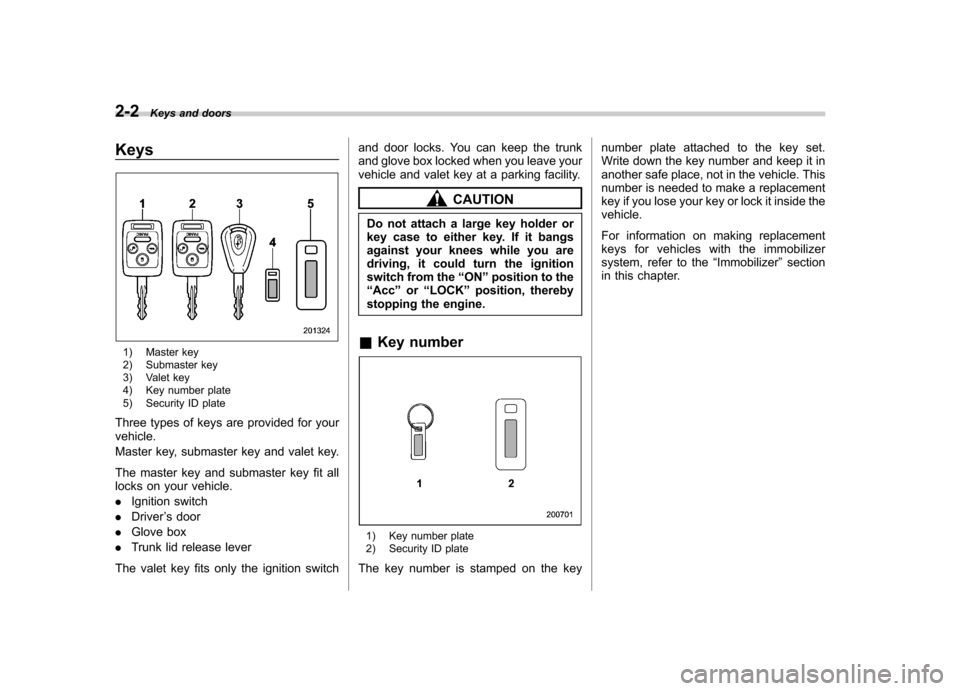
1) Master key
2) Submaster key
3) Valet key
4) Key number plate
5) Security ID plate
Three types of keys are provided for your vehicle.
Master key, submaster key and valet key.
The master key and submaster key fit all
locks on your vehicle. . Ignition switch
. Driver ’s door
. Glove box
. Trunk lid release lever
The valet key fits only the ignition switch and door locks. You can keep the trunk
and glove box locked when you leave your
vehicle and valet key at a parking facility.
CAUTION
Do not attach a large key holder or
key case to either key. If it bangs
against your knees while you are
driving, it could turn the ignition
switch from the “ON ”position to the
“ Acc ”or “LOCK ”position, thereby
stopping the engine.
& Key number
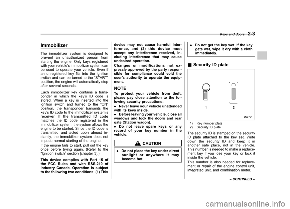
1) Key number plate
2) Security ID plate
The key number is stamped on the key number plate attached to the key set.
Write down the key number and keep it in
another safe place, not in the vehicle. This
number is needed to make a replacement
key if you lose your key or lock it inside thevehicle.
For information on making replacement
keys for vehicles with the immobilizer
system, refer to the
“Immobilizer ”section
in this chapter.
Page 92 of 444

Immobilizer
The immobilizer system is designed to
prevent an unauthorized person from
starting the engine. Only keys registered
with your vehicle’s immobilizer system can
be used to operate your vehicle. Even if
an unregistered key fits into the ignition
switch and can be turned to the “START ”
position, the engine will automatically stop
after several seconds.
Each immobilizer key contains a trans-
ponder in which the key ’s ID code is
stored. When a key is inserted into the
ignition switch and turned to the “ON ”
position, the transponder transmits thekey ’s ID code to the immobilizer system ’s
receiver. If the transmitted ID code
matches the ID code registered in the
immobilizer system, the system allows the
engine to be started. Since the ID code is
transmitted and acted upon almost in-
stantly, the immobilizer system does not
impede normal starting of the engine.
If the engine fails to start, pull out the key
once before trying again. (Refer to the“ Ignition switch ”section [chapter 3].)
This device complies with Part 15 of
the FCC Rules and with RSS-210 of
Industry Canada. Operation is subject
to the following two conditions: (1) This device may not cause harmful inter-
ference, and (2) this device must
accept any interference received, in-
cluding interference that may cause
undesired operation.
Changes or modifications not ex-
pressly approved by the party respon-
sible for compliance could void theuser
’s authority to operate the equip-
ment.
NOTE
To protect your vehicle from theft,
please pay close attention to the fol-
lowing security precautions: . Never leave your vehicle unattended
with its keys inside. . Before leaving your vehicle, close all
windows and lock the doors and rear
gate (Station wagon).. Do not leave spare keys or any
record of your key number in thevehicle.
CAUTION
. Do not place the key under direct
sunlight or anywhere it may
become hot. .
Do not get the key wet. If the key
gets wet, wipe it dry with a cloth
immediately.
& Security ID plate
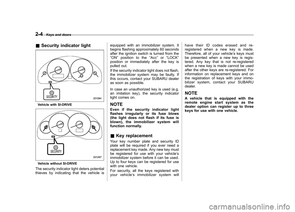
1) Key number plate
2) Security ID plate
The security ID is stamped on the security
ID plate attached to the key set. Write
down the security ID and keep it in
another safe place, not in the vehicle.
This number is needed to make a replace-
ment key if you lose your key or lock it
inside the vehicle.
This number is also needed for replace-
ment or repair of the engine control unit,
integrated unit, and combination meter. Keys and doors
2-3
– CONTINUED –
Page 93 of 444

2-4Keys and doors
& Security indicator light
Vehicle with SI-DRIVE
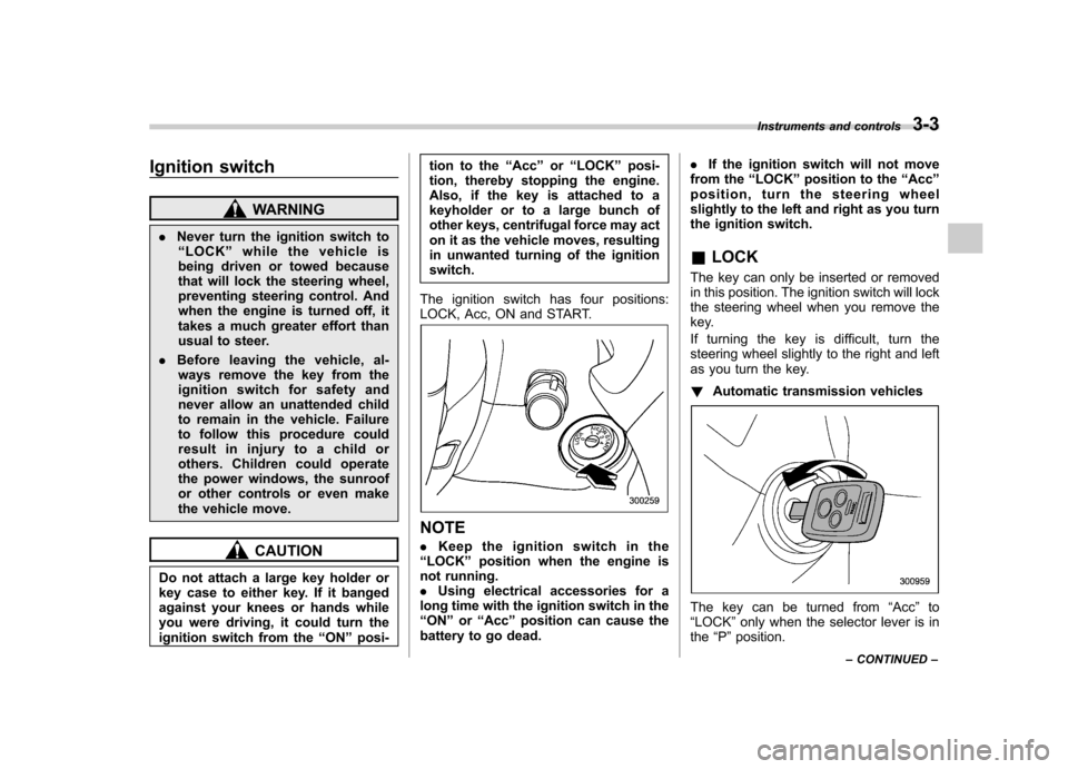
Vehicle without SI-DRIVE
The security indicator light deters potential
thieves by indicating that the vehicle is equipped with an immobilizer system. It
begins flashing approximately 60 seconds
after the ignition switch is turned from the“
ON ”position to the “Acc ”or “LOCK ”
position or immediately after the key is
pulled out.
If the security indicator light does not flash,
the immobilizer system may be faulty. If
this occurs, contact your SUBARU dealer
as soon as possible.
In case an unauthorized key is used (e.g.
an imitation key), the security indicator
light comes on.
NOTE
Even if the security indicator light
flashes irregularly or its fuse blows
(the light does not flash if its fuse is
blown), the immobilizer system will
function normally. & Key replacement
Your key number plate and security ID
plate will be required if you ever need a
replacement key made. Any new key must
be registered for use with your vehicle ’s
immobilizer system before it can be used.
Up to four keys can be registered for use
with one vehicle.
For security, all the keys registered with
your vehicle ’s immobilizer system will have their ID codes erased and re-
registered when a new key is made.
Therefore, all of your vehicle
’s keys must
be presented when a new key is regis-
tered. Any key that is not re-registered
when a new key is made cannot be used
after the other keys are re-registered. For
information on replacement keys and on
the registration of keys with your immo-
bilizer system, contact your SUBARU
dealer.
NOTE
A vehicle that is equipped with the
remote engine start system as the
dealer option can register up to three
keys for use with one vehicle.
Page 105 of 444

2-16Keys and doors
alarm: OFF ”and the horn sounds twice,
indicating that the system is now deacti- vated.
If the system was previously deacti- vated:
For a vehicle without SI-DRIVE, the
odometer/trip meter screen displays “AL
on ”, and for a vehicle with SI-DRIVE, the
multi-information display shows “Security
alarm: ON ”and the horn sounds once,
indicating that the system is now acti-vated.
NOTE
You may have the above setting
change done by your SUBARU dealer. & If you have accidentally trig-
gered the alarm system
! To stop the alarm
Do any of the following operations: . Insert the key in the door lock of the
driver ’s door and turn it to the unlock
position.. Press any button on the remote trans-
mitter.. Turn the ignition switch to the “ON ”
position. &
Arming the system
! To arm the system using remote transmitter
1. Close all windows and the moonroof (if
so equipped).
2. Remove the key from the ignition switch.
3. Open the doors and get out of the vehicle.
4. Make sure that the engine hood (and
the trunk lid on the Sedan) are locked.
5. Close all doors (and the rear gate on
the Station wagon).
: Press to Arm the system.: Press to Disarm the system.
Vehicle with SI-DRIVE
Vehicle without SI-DRIVE
6. Briefly press the “
”button (for less
than 2 seconds). All doors (and the rear
gate on the Station wagon) will lock, an
electronic chirp will sound once, the turn
Page 106 of 444

signal lights will flash once, and the
indicator lights will start flashing rapidly.
After rapid flashing for 30 seconds (stand-
by time), the indicator lights will then flash
slowly (twice approximately every 2 sec-
onds), indicating that the system has been
armed for surveillance.
If any of the doors, (rear gate or trunk lid)
is not fully closed, an electronic chirp
sounds five times, the turn signal lights
flash five times to alert you that the doors
(or the rear gate) are not properly closed.
When you close the door, the system will
automatically arm and doors will automa-
tically lock. !To arm the system using power
door locking switches
1. Close all windows.
2. Remove the key from the ignition switch.
3. Open the doors and get out of the vehicle.
4. Make sure that the engine hood is locked.
5. Close the doors (and the rear gate on
the station wagon) but leave only thedriver ’s door or the front passenger ’s door
open.
6. Push the front side ( “LOCK ”side) of
the power door locking switch to set the
door locks.
7. Close the door. An electronic chirp will
sound once, the turn signal lights will flash
once and the indicator lights will start
flashing rapidly. After rapid flashing for 30
seconds (standby time), the indicator
lights will then flash slowly (twice approxi-
mately every 2 seconds), indicating that
the system has been armed for surveil-lance.
NOTE . The system can be armed even if the
engine hood, the windows and/or
moonroofs are opened. Always make
sure that they are fully closed before
arming the system. .
The 30-second standby time can be
eliminated if you prefer. Have it per-
formed by your SUBARU dealer.. If your vehicle is a Sedan and you
unlock the trunk using the remote
transmitter ’s “
”buttonwiththe
alarm system armed, the system will
be temporarily placed in a standby
state. The system will go back to the
surveillance state upon locking thetrunk.. The system is in the standby mode
for a 30-second period after locking the
doors with the remote transmitter. The
security indicator light will flash at
short intervals during this period. . If any of the following actions is
done during the standby period, the
system will not switch to the surveil-
lance state.
.Doors are unlocked using the
remote transmitter. . Any door (including the rear gate
of a Station wagon or the trunk of a
Sedan) is opened. . Ignition switch is turned to the
“ ON ”position. Keys and doors
2-17
– CONTINUED –
Page 120 of 444

Ignition switch..................................................... 3-3
LOCK .................................................................. 3-3
Acc..................................................................... 3-4
ON...................................................................... 3-4
START ................................................................ 3-4
Key reminder chime ............................................ 3-5
Ignition switch light ............................................. 3-5
Hazard warning flasher ....................................... 3-5
Meters and gauges (Vehicle with SI-DRIVE) ...... 3-5
Combination meter illumination ........................... 3-5
Speedometer ....................................................... 3-6
Tachometer ......................................................... 3-6
Fuel gauge .......................................................... 3-6
Temperature gauge ............................................. 3-7
ECO gauge ......................................................... 3-8
Multi-information display (Vehicle with SI-DRIVE) .................................... 3-9
Display ............................................................... 3-9
Operation switch ................................................. 3-9
Odometer and trip meter .................................... 3-10
Current and average fuel consumption ............... 3-11
Outside temperature and journey time ................ 3-12
Driving range on remaining fuel .......................... 3-14
Clock (Vehicle with Navigation System) ............... 3-15
SI-DRIVE display ................................................ 3-15
Meter settings .................................................... 3-15
Warning messages and driver ’s information ........ 3-20
Meters and gauges (Vehicle without SI-DRIVE) ............................. 3-24
Combination meter illumination .......................... 3-24 Canceling the function for meter/gauge needle
movement upon turning on the ignition switch ............................................................. 3-24
Speedometer ..................................................... 3-24
Odometer .......................................................... 3-25
Double trip meter ............................................... 3-25
Tachometer ....................................................... 3-26
Fuel gauge ........................................................ 3-26
Temperature gauge ............................................ 3-27
Warning and indicator lights ............................. 3-28
Seatbelt warning light and chime ....................... 3-29
SRS airbag system warning light ........................ 3-30
Front passenger ’s frontal airbag ON and OFF
indicators ........................................................ 3-31
CHECK ENGINE warning light/Malfunction indicator lamp ................................................. 3-31
Charge warning light .......................................... 3-32
Oil pressure warning light .................................. 3-32
AT OIL TEMPerature warning light (AT models) ..................................................... 3-32
Low tire pressure warning light (U.S.-spec. models) ........................................................... 3-32
ABS warning light .............................................. 3-34
Brake system warning light ................................ 3-35
Low fuel warning light ....................................... 3-35
Door open warning light .................................... 3-36
All-Wheel Drive warning light (AT models) ..... ..... 3-36
Vehicle Dynamics Control operation indicator light (if equipped). ............................................ 3-36
Vehicle Dynamics Control warning light (if equipped)/Vehicle Dynamics Control OFF
indicator light (if equipped) .............................. 3-37
Instruments and controls
3
Page 122 of 444

Ignition switch
WARNING
. Never turn the ignition switch to
“ LOCK ”while the vehicle is
being driven or towed because
that will lock the steering wheel,
preventing steering control. And
when the engine is turned off, it
takes a much greater effort than
usual to steer.
. Before leaving the vehicle, al-
ways remove the key from the
ignition switch for safety and
never allow an unattended child
to remain in the vehicle. Failure
to follow this procedure could
result in injury to a child or
others. Children could operate
the power windows, the sunroof
or other controls or even make
the vehicle move.
CAUTION
Do not attach a large key holder or
key case to either key. If it banged
against your knees or hands while
you were driving, it could turn the
ignition switch from the “ON ”posi- tion to the
“Acc ”or “LOCK ”posi-
tion, thereby stopping the engine.
Also, if the key is attached to a
keyholder or to a large bunch of
other keys, centrifugal force may act
on it as the vehicle moves, resulting
in unwanted turning of the ignitionswitch.
The ignition switch has four positions:
LOCK, Acc, ON and START.
NOTE . Keep the ignition switch in the
“ LOCK ”position when the engine is
not running. . Using electrical accessories for a
long time with the ignition switch in the“ ON ”or “Acc ”position can cause the
battery to go dead. .
If the ignition switch will not move
from the “LOCK ”position to the “Acc ”
position, turn the steering wheel
slightly to the left and right as you turn
the ignition switch. & LOCK
The key can only be inserted or removed
in this position. The ignition switch will lock
the steering wheel when you remove the
key.
If turning the key is difficult, turn the
steering wheel slightly to the right and left
as you turn the key. ! Automatic transmission vehicles
The key can be turned from “Acc ”to
“ LOCK ”only when the selector lever is in
the “P ”position. Instruments and controls
3-3
– CONTINUED –