Page 49 of 258

Child safety47
Safety First
Operating instructions
Tips and Maintenance
Te c h n i c a l D a t a
Securing child seatsWays to secure a child seat
A child seat can be secured differently on th e rear seat and on the front passenger seat.You can secure a child seat to the rear seat or front passenger seat in the
following ways:•
Child seats in groups 0 to 3 can be secured with a seat belt.
•
Child seats from the groups 0, 0+ and 1 using the “ISOFIX” and
“Toptether” systems or the antirotation system may be secured without using
the adult seatbelt and using the “ISOFIX” and “Toptether” anchors or the anti-
rotation mechanism/brackets ⇒page 48.
U: Suitable for universal approved rest raining systems for use in this age
category (universal retention systems are those fitted using the adult
seat belt.
UF Suitable for universal forward-facing retention systems approved for use with this age group.
*: Move the passenger seat as far to rear as possible, as high as possible and always deactivate the airbag.
L: Suitable for retention systems us ing the “ISOFIX” and “Toptether”
anchors or antirotation mechanism/bracket
X Seat position not suitable for children in this age group.
WARNING
•
When travelling, children must be secured in the vehicle with a
restraint system suitable for age, weight and size.
•
Never install a child seat facing backwards (or rear-facing) on the front
passenger seat unless the front passenger airbag has been disabled. This
represents a risk of fatal injuries to the child! However, if a child must,
under exceptional circumstances, travel in the front passenger seat, the
passenger airbag must be deactivated ⇒page 40, “Deactivating airbags*”
and the seat put into the highest position where possible.
•
Read and always observe information and warnings concerning the use
of child seats ⇒ in “Safety notes on using child seats” on page 43.
Weight class
Weight Seat locations
Front passenger Rear outerRear centre
Group 0 <10 kgU*UU
Group 0+ <13 kgU*UU
Group 1 9-18 kgU*U/L U
Group 2 / 3 15-36 kgXUF UF
COR_ING_0707 Seite 47 Mittwoch, 1. August 2007 6:25 18
Page 50 of 258

Child safety
48Securing the child seat using the “ISOFIX” and “Toptether” system or the antirotation mechanism/system
Child seats with the “ISOFIX” and “Toptether” system can be
secured quickly, easily and safely on the rear outer seats.When removing or fitting the child seat, please be sure to follow the
manufacturer's instructions.
– Move the seat as far to rear as it will go.
– Press the child seat onto the “ISOFIX” retaining rings until the
child seat can be heard to engage securely. If the child seat is
equipped with “Toptether” anchor points, secure it to the corre-
spondent ring. If the child seat is fitted with any other antirota-
tion system, follow the manufacturer instructions carefully.
– Pull on both sides of the child se at to ensure that it is secure.
Two“ISOFIX” retaining rings are fitted on each rear seat. In some vehicles, the
rings are secured to the seat frame and in others they are secured to the rear
floor. Access to “ISOFIX” rings is between the rear back rest and the seat.
“Toptether” rings are located in the space behind the rear seats. They are
often located on the rear of the seat backs.
Child seats with “ISOFIX” and “Topteth er” mountings are available from the
Authorised Service Centres.
WARNING
•
The retaining rings are designed only for use with “ISOFIX” and
“Toptether” child seats.
•
Never secure child seats that do not have the “ISOFIX” or Toptether
system, retaining belts or objects to the fastening rings – this can result in
potentially fatal injuries to the child!
•
Ensure that the child seat is secu red correctly using the “ISOFIX” and
Toptether anchors.
Fig. 30 ISOFIX securing
rings
COR_ING_0707 Seite 48 Mittwoch, 1. August 2007 6:25 18
Page 51 of 258
49
Safety First
Operating instructions
Tips and Maintenance
Te c h n i c a l D a t a
COR_ING_0707 Seite 49 Mittwoch, 1. August 2007 6:25 18
Page 52 of 258
50
Fig. 31 Instrument panelCOR_ING_0707 Seite 50 Mittwoch, 1. August 2007 6:25 18
Page 53 of 258

Cockpit51
Safety First
Operating instructions
Tips and Maintenance
Te c h n i c a l D a t a
Operating instructionsCockpitOverviewOverview of the instrument panel
This overview will help you to familiarise yourself with the
controls and displays.
Door release lever
Air vent
Light switch . . . . . . . . . . . . . . . . . . . . . . . . . . . . . . . . . . . . . . . . .
Light dimmer for instrument panel ligh ting* . . . . . . . . . . . . . .
Headlight range control* . . . . . . . . . . . . . . . . . . . . . . . . . . . . . .
Turn signal and dipped beam lever and cruise control system*
Instrument panel an d warning lights:
− Instruments . . . . . . . . . . . . . . . . . . . . . . . . . . . . . . . . . . . . . . .
− Indication lamps . . . . . . . . . . . . . . . . . . . . . . . . . . . . . . . . . . .
Horn (works only when the igni tion is on)/ and driver front
airbag* . . . . . . . . . . . . . . . . . . . . . . . . . . . . . . . . . . . . . . . . . . . . .
Steering and starter lock . . . . . . . . . . . . . . . . . . . . . . . . . . . . . .
Windscreen wiper and windscreen wash lever and operation of
the multi-function display* . . . . . . . . . . . . . . . . . . . . . . . . . . . . .
Switch for hazard warning lights . . . . . . . . . . . . . . . . . . . . . . . .
Switch for heated rear window . . . . . . . . . . . . . . . . . . . . . . . . . .
Airbag disconnected warning light* . . . . . . . . . . . . . . . . . . . . .
Cup holder* . . . . . . . . . . . . . . . . . . . . . . . . . . . . . . . . . . . . . . . . . Radio casing*/Radio navigation system*
Passenger airbag* . . . . . . . . . . . . . . . . . . . . . . . . . . . . . . . . . . .
Glove box/Stowage compartment . . . . . . . . . . . . . . . . . . . . . . .
Switches for:
−
Heating and ventilation . . . . . . . . . . . . . . . . . . . . . . . . . . . . .
− Air conditioning* . . . . . . . . . . . . . . . . . . . . . . . . . . . . . . . . . .
− Climatronic* . . . . . . . . . . . . . . . . . . . . . . . . . . . . . . . . . . . . . .
Ashtray/ cigarette lighter/socket . . . . . . . . . . . . . . . . . . . . . . . .
Handbrake lever . . . . . . . . . . . . . . . . . . . . . . . . . . . . . . . . . . . . .
Automatic / manual gearbox lever* . . . . . . . . . . . . . . . . . . . . .
Pedals . . . . . . . . . . . . . . . . . . . . . . . . . . . . . . . . . . . . . . . . . . . . .
Controls on the steering wheel* . . . . . . . . . . . . . . . . . . . . . . . . .
Steering column control lever* . . . . . . . . . . . . . . . . . . . . . . . . .
Stowage compartment . . . . . . . . . . . . . . . . . . . . . . . . . . . . . . . .
Bonnet release lever . . . . . . . . . . . . . . . . . . . . . . . . . . . . . . . . . .
Control for adjusting electric wing mirrors* . . . . . . . . . . . . . . .
Central locking button* . . . . . . . . . . . . . . . . . . . . . . . . . . . . . . .
Electric window controls* . . . . . . . . . . . . . . . . . . . . . . . . . . . . .
Note
Some of the items of equipment listed here are fitted only on certain
models/model years or are optional extras.
A1A2A3
89
A4
90
A5
90
A6
92, 139
A7
52
60
A8
27
A9
129
A10
96, 55
A11
91
A12
90
A13
28
A14
110
A15A16
30
A17
108
A18
116
119
122
A19
111
A20
138
A21
134,133
A22
14
A23
68
A24
127
A25
108
A26
177
A27
100
A28
73
A29
84
COR_ING_0707 Seite 51 Mittwoch, 1. August 2007 6:25 18
Page 54 of 258
Cockpit
52InstrumentsInstrument overview
The instruments display the vehicle operating status.Fig. 32 Detailed view of dash panel instrument panelThe layout of the instruments depends upon the model and engine.
Rev counter* ⇒ page 53
Coolant temperature gauge ⇒page 53
Fuel gauge ⇒ page 54
Speedometer ⇒page 54 Digital clock*/Outside temperature display*/Multifunction display
⇒
page 54
Display field for selector lever position ⇒page 58
Distance display with service interval display* ⇒page 58A1A2A3A4
A5A6A7
COR_ING_0707 Seite 52 Mittwoch, 1. August 2007 6:25 18
Page 55 of 258

Cockpit53
Safety First
Operating instructions
Tips and Maintenance
Te c h n i c a l D a t a
Rev counter
The rev. counter displays the engine speed in revolutions per
minute.The start of the red zone on the dial ⇒ page 52, fig. 32 indicates the
maximum engine speed which may be used briefly when the engine is warm
and after it has been run in properly. However, it is advisable to change up a
gear or move the selector lever to D (or li ft your foot off the accelerator) before
the needle reaches the red zone.
Caution
The rev counter needle must never enter the red zone on the scale. Risk of
engine damage.
For the sake of the environment
Changing up a gear early will help you to save fuel and minimise engine
noise.
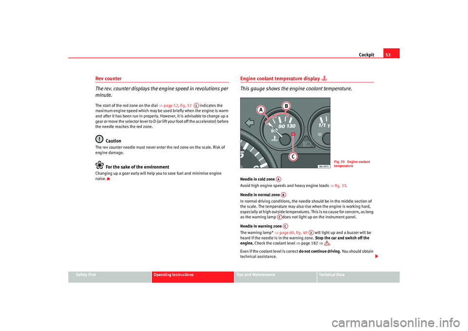
Engine coolant temperature display
This gauge shows the engine coolant temperature.
Needle in cold zone
Avoid high engine speeds and heavy engine loads ⇒fig. 33.
Needle in normal zone
In normal driving conditions, the needle should be in the middle section of
the scale. The temperature may also rise when the engine is working hard,
especially at high outside temperatures. This is no cause for concern, as long
as the warning lamp does not li ght up on the instrument panel.
Needle in warning zone
The warning lamp* ⇒page 60, fig. 40 will light up and a buzzer will be
heard if the needle is in the warning zone. Stop the car and switch off the
engine. Check the coolant level ⇒ page 182 ⇒.
Even if the coolant level is correct do not continue driving. You should obtain
technical assistance.
A1
Fig. 33 Engine coolant
temperature
AAABACAC
A2
COR_ING_0707 Seite 53 Mittwoch, 1. August 2007 6:25 18
Page 56 of 258

Cockpit
54
WARNING
When working in the engine compartment, always bear in mind the safety
warnings ⇒ page 175.
Caution
Accessories in front of the air inlet reduce the cooling effect of the coolant. At
high outside temperatures and high engine loads, there is a risk of the
engine overheating.Fuel gauge
and reserve indicator
Instrument panel: fuel gauge
The fuel tank has a capacity of approx. 45 litres. When the needle reaches the reserve zone
⇒fig. 34 the warning lamp will
light and an acoustic signal will sound reminding the driver to refuel. At this
point there are still about 7 litres of fuel in the tank.
SpeedometerThe speedometer is equipped with a digital odometer and a trip counter, in
addition to a service intervals display.
During the running-in period, the instructions shown on ⇒page 147 should
be followed.Digital display in the instrument panel Digital clock* – Turn the setting knob ⇒page 52, fig. 32 anti-clockwise to
the stop to set the hour. If the kn ob is turned briefly anti-clock-
wise the clock will advance one hour further.
– Turn the setting knob clockwise to the limit stop to set the minutes. If the knob is turned briefly clockwise the clock will
advance one minute further.
Fig. 34 Fuel gauge
A5
COR_ING_0707 Seite 54 Mittwoch, 1. August 2007 6:25 18