2008 RENAULT SCENIC steering column switch
[x] Cancel search: steering column switchPage 25 of 391

PASSENGER COMPARTMENT CONNECTION UNIT
Fault finding - System operation
87B
87B-25
PASSENGER COMPARTMENT CONNECTION UNIT
Fault finding - System operation
87B
87B-25V9 MR-372-J84-87B000$086.mif
UCH
Vdiag No.: 44, 48,
4C, 4D, 4F, 50
1.2.2 Unlocking/locking the steering column:
1Steering column lock
2multiplex line
3Supply
4Sensor Line
5Safety line
a/ Unlocking the steering column lock
Following authentication of the Renault card:
1/ The UCH sends a code to the electric steering column lock with an unlocking request via the multiplex network
(ET119 UCH request to steering column lock).
2/ If the electric steering column lock recognises the code, it unlocks and sends its unlocked status to the UCH
(ET073 Steering column lock sensor signal).
3/ When the UCH receives the "Steering column unlocking completed" signal, it orders the Protection and Switching
Unit to activate the + after ignition relay and the procedure continues.
The physical status of the column lock can be displayed by status ET072 Steering column lock and its
programming can be displayed by status ET071 Steering column lock blank.
The steering column lock remains locked if:
–There is excessive mechanical load on the steering column (e.g.: wheel jammed against a kerb),
–the battery voltage is too low,
–the power demanded by the column lock is too high (thermal protection of the column lock electric motor). Note:
After ignition feed can only be established if the steering column unlocking procedure is performed
correctly.
Page 33 of 391

PASSENGER COMPARTMENT CONNECTION UNIT
Fault finding - System operation
87B
87B-33
PASSENGER COMPARTMENT CONNECTION UNIT
Fault finding - System operation
87B
87B-33V9 MR-372-J84-87B000$086.mif
UCH
Vdiag No.: 44, 48,
4C, 4D, 4F, 50
1.4.1.6 The door locking motors:
These are direct current motors (12 V supply). The door locking motors are controlled by the UCH.
The deadlocking function requires a second motor per door.
1.4.2 Main components of the PROTECTION sub-function:
The protection sub-function is based on 4 main coded components:
–The Renault cards.
–The UCH.
–The electric steering column lock.
–The injection computer.
These parts are coded definitively: a part coded for one vehicle may not be used on another vehicle.
It is possible to replace a coded part with an uncoded part using special procedures in the CLIP tool and the vehicle
repair code (See Configuration and programming).
1.4.2.1 The Renault card:
The Renault card enables the vehicle to be started in two modes:
–starting by inserting the card into the reader:
–hands-free starting without insertion of the card into the card reader (hands-free vehicles).
The Renault card is powered by a 3 V battery. This battery is necessary to operate in standard and hands-free mode.
If the battery is too old, or if the vehicle is in an area of frequency interference, hands-free starting is not possible, but
always possible by inserting the Renault card into the reader.
1.4.2.2 The UCH:
a) The UCH detects the starting request (Start button pressed under starting conditions).
b) The UCH authenticates the Renault card via the starting aerials for hands-free mode, or via the card reader for
transponder mode.
c) The UCH manages the exchange with the steering column lock:
The UCH sends an unlocking request to the steering column via the vehicle's multiplex network, and the steering
column responds with the status of the lock bolt.
d) The UCH requests activation of the + after ignition feed from the Protection and Switching Unit.
e) The UCH manages the exchange with the injection computer:
The UCH and the injection computer exchange their codes via the vehicle's multiplex network to deactivate protection
and unlock the immobiliser.
f) The UCH requests the Protection and Switching Unit to supply the starter motor.
Page 34 of 391

PASSENGER COMPARTMENT CONNECTION UNIT
Fault finding - System operation
87B
87B-34
PASSENGER COMPARTMENT CONNECTION UNIT
Fault finding - System operation
87B
87B-34V9 MR-372-J84-87B000$086.mif
UCH
Vdiag No.: 44, 48,
4C, 4D, 4F, 50
1.4.2.3 The electric steering column lock:
The electric steering column lock is controlled by the UCH. The steering column lock works by inserting and
removing a lock bolt. It replaces the Neimann type lock.
The steering column lock is powered outside + after ignition feed. The steering column lock supply is via the after
ignition relay (located in the Protection and Switching Unit) in its rest position, from where it is distributed to the
column lock by the UCH.
The UCH sends an unlocking request and a code to the steering column lock, via the vehicle's multiplex network.
The multiplex network unlocks the steering column lock if the code is recognised.
A sensor located on the column lock bolt informs the UCH, via the multiplex network and by wire connection, that it
is unlocked.
When unlocking is confirmed, the UCH activates the + after ignition feed via the Protection and Switching Unit. The
column lock is no longer supplied.
The column lock has a "+ after ignition feed present on vehicle" wire signal which inhibits locking while the feed is
active.
1.4.2.4 The injection computer:
The injection computer is coded and unlocks following the encrypted challenge exchange with the UCH.
1.4.2.5 The starting aerials (hands-free vehicles):
There are 3 transmitter aerials located in the passenger compartment. They are controlled by the UCH to interrogate
the card during a starting request or in confirming the presence of the card in the vehicle (e.g. after a door is
opened).
The power used allows the whole passenger compartment to be covered, including the boot. Overspill outside the
passenger compartment is minimal.
1.4.2.6 The card reader:
The card reader is connected to the UCH by a wire connection. It provides the transponder function (like a key
recognition ring). It therefore allows authentication of a Renault card without a battery.
If the card is not detected or recognised during hands-free starting, the card reader flashes to tell the customer to
insert the Renault card.IMPORTANT IMPORTANT
The steering column lock is:
–not removable when the bolt is disengaged,
–fitted with a left-hand thread self-shearing mounting bolt.
Page 39 of 391

PASSENGER COMPARTMENT CONNECTION UNIT
Fault finding - System operation
87B
87B-39
PASSENGER COMPARTMENT CONNECTION UNIT
Fault finding - System operation
87B
87B-39V9 MR-372-J84-87B000$129.mif
UCH
Vdiag No.: 44, 48,
4C, 4D, 4F, 50
3.2 Sub-function: WIPER POWER
The UCH controls the rear screen wiper's power (and that of the headlight washers if the vehicle is fitted with xenon
headlights and a SIEMENS Vdiag 44 UPC).
Their operation can be checked using commands AC007 Rear screen wiper, AC030 Headlight washer relay 1
and AC031 Headlight washer relay 2.
Rain and light sensor
Information displays Multiplex network
Steering column
control
UCH Protection and
Switching Unit
Rear screen wiper Rear screen wiper
Windscreen and rear
screen washers
Headlight
washers
Page 40 of 391
PASSENGER COMPARTMENT CONNECTION UNIT
Fault finding - System operation
87B
87B-40
PASSENGER COMPARTMENT CONNECTION UNIT
Fault finding - System operation
87B
87B-40V9 MR-372-J84-87B000$129.mif
UCH
Vdiag No.: 44, 48,
4C, 4D, 4F, 50
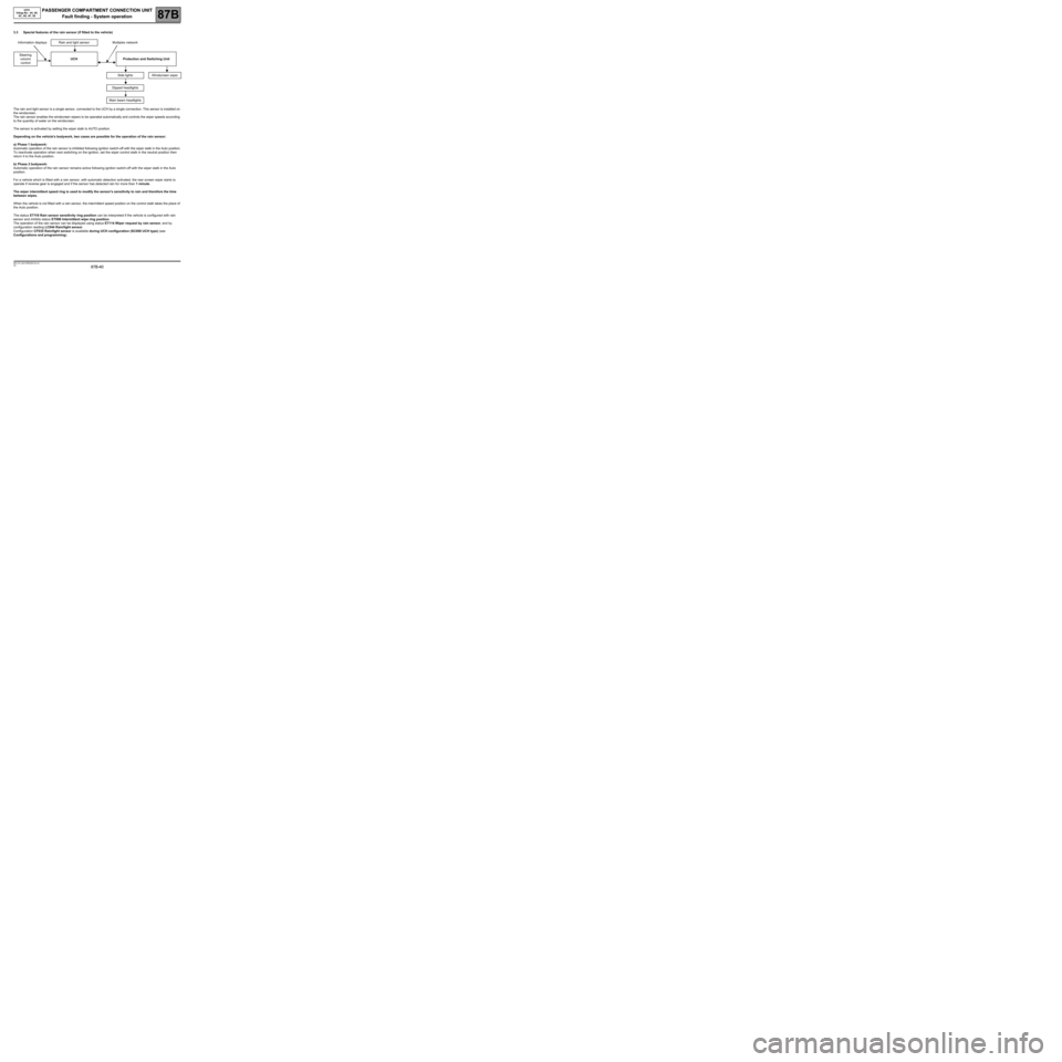
3.3 Special features of the rain sensor (if fitted to the vehicle)
The rain and light sensor is a single sensor, connected to the UCH by a single connection. This sensor is installed on
the windscreen.
The rain sensor enables the windscreen wipers to be operated automatically and controls the wiper speeds according
to the quantity of water on the windscreen.
The sensor is activated by setting the wiper stalk to AUTO position.
Depending on the vehicle's bodywork, two cases are possible for the operation of the rain sensor:
a) Phase 1 bodywork:
Automatic operation of the rain sensor is inhibited following ignition switch-off with the wiper stalk in the Auto position.
To reactivate operation when next switching on the ignition, set the wiper control stalk in the neutral position then
return it to the Auto position.
b) Phase 2 bodywork:
Automatic operation of the rain sensor remains active following ignition switch-off with the wiper stalk in the Auto
position.
For a vehicle which is fitted with a rain sensor, with automatic detection activated, the rear screen wiper starts to
operate if reverse gear is engaged and if the sensor has detected rain for more than 1 minute.
The wiper intermittent speed ring is used to modify the sensor's sensitivity to rain and therefore the time
between wipes.
When the vehicle is not fitted with a rain sensor, the intermittent speed position on the control stalk takes the place of
the Auto position.
The status ET118 Rain sensor sensitivity ring position can be interpreted if the vehicle is configured with rain
sensor and inhibits status ET096 Intermittent wipe ring position.
The operation of the rain sensor can be displayed using status ET114 Wiper request by rain sensor, and by
configuration reading LC044 Rain/light sensor.
Configuration CF035 Rain/light sensor is available during UCH configuration (SC008 UCH type) (see
Configurations and programming). Information displays Rain and light sensor Multiplex network
Steering
column
control UCH Protection and Switching Unit
Side lights Windscreen wiper
Dipped headlights
Main beam headlights
Page 43 of 391

PASSENGER COMPARTMENT CONNECTION UNIT
Fault finding - System operation
87B
87B-43
PASSENGER COMPARTMENT CONNECTION UNIT
Fault finding - System operation
87B
87B-43V9 MR-372-J84-87B000$129.mif
UCH
Vdiag No.: 44, 48,
4C, 4D, 4F, 50
4FUNCTION: LIGHTING
4.1 Sub-function: LIGHTING CONTROL
The UCH receives the request from the driver, from the lighting stalk, from the hazard warning lights button and, if
fitted to the vehicle, from the light detector.
The UCH requests the Protection and Switching Unit, via the multiplex network, to provide power to the side lights,
dipped headlights, main beam headlights and fog lights (front).
If a request to activate the lighting is made, the UPC provides power to the xenon bulb computers.
The dipped headlights are still supplied when the main beam headlights are activated.
The following statuses can be displayed:
ET081 Lighting stalk position.
ET082 Rear fog lights request.
ET085 Hazard warning lights switch.
ET083 Left-hand direction indicator request.
ET084 Right-hand indicator request.
If the UCH cannot determine the position of the control stalk, or inform the Protection and Switching Unit of the
control stalk's position, the Protection and Switching Unit will activate the dipped headlights.
4.2 Sub-function: LIGHTING POWER
The UCH controls the power supply for the rear fog light (a single one), direction indicators and interior lighting (roof
lights and footwell/floor lights).
The interior lighting request can be displayed using the ET112 Interior lighting control status.
Operation of the lights powered by the UCH can be checked using the actuator commands AC009 Rear fog lights,
AC022 Left-hand direction indicator, AC023 Right-hand direction indicator, AC021 Interior lights and AC027
Footwell/floor lighting.
Information displays Rain and light sensor Multiplex network
Steering column
controlUCHProtection and Switching
Unit
Rear fog light
Direction indicators
Interior lighting
Side lightsMain beam
headlights
Dipped
headlightsFront fog lights
Page 45 of 391

PASSENGER COMPARTMENT CONNECTION UNIT
Fault finding - System operation
87B
87B-45
PASSENGER COMPARTMENT CONNECTION UNIT
Fault finding - System operation
87B
87B-45V9 MR-372-J84-87B000$129.mif
4.4 Special features of the light sensor (if fitted to the vehicle).
Information displays Rain and light sensor Multiplex network
Steering column
controlUCHProtection and Switching
Unit
The rain and light sensor is a single sensor, connected to the UCH by a single connection. This sensor is installed on
the windscreen.
The light sensor enables the side lights and dipped headlights to be operated automatically as soon as the vehicle is
in a dark place (tunnel, night, gloomy weather conditions, etc.).
The status of the light sensor can be displayed using ET115 Lights on request by light sensor, and by configuration
reading LC044 Rain/light sensor.
Configuration CF035 Rain/light sensor is available during UCH configuration SC008 UCH type (see
Configurations and programming).
To activate the automatic lighting function, press the AUTO button on the lighting stalk for at least 4 seconds. This
action is confirmed by two beeps.
To deactivate the automatic lighting function, switch the engine off and press the AUTO button on the lighting stalk
for at least 4 seconds. A beep confirms this action and the message Automatic lighting OFF appears on the
instrument panel.
Any other operation on the lighting stalk overrides and cancels automatic operation.
UCH
Vdiag No.: 44, 48,
4C, 4D, 4F, 50
Side lightsWindscreen
wiper
Dipped
headlights
Main beam
headlights
Page 51 of 391

PASSENGER COMPARTMENT CONNECTION UNIT
Fault finding - Configurations and programming
87B
87B-51
PASSENGER COMPARTMENT CONNECTION UNIT
Fault finding - Configurations and programming
87B
87B-51V9 MR-372-J84-87B000$215.mif
UCH
Vdiag No.: 44, 48,
4C, 4D, 4F, 50PASSENGER COMPARTMENT CONNECTION UNIT
Fault finding - Configurations and programming
1/ GENERAL INFORMATION
The engine immobiliser protection system is controlled by a RENAULT card recognition system with random rolling
code.
A coded transponder chip (operating without a battery) independent of the remote control function is built into each
of the vehicle's RENAULT Cards.
The engine immobiliser is active a few seconds after the RENAULT Card is removed from the card reader. Its status
is shown by the flashing warning light on the instrument panel and by locking of the steering column lock.
To obtain the immobiliser code, see Technical Note 5037A, Code delivery procedure.
There are two programming methods: "Not connected" to the code server mode and "connected" to the code
server mode.
–In the "not connected" mode, the CLIP diagnostic tool supplies a programming key and the user enters the
immobiliser code.
–In the "connected" mode, the CLIP diagnostic tool automatically exchanges the programming key and the
immobiliser code.
IMPORTANT
If not all of the Renault cards are available, reallocate all Renault cards later. Cards not inserted will no longer be
allocated to this vehicle.
IMPORTANT
In "not connected" mode, once the tool has issued the programming key, the user has a limited amount of time
in which to enter the immobiliser code.
If this time expires, the CLIP diagnostic tool displays the message "Time expired. Restart the procedure.
Note:
When only the UCH is replaced, there is no operation to perform on the injection computer or the steering column
lock, they retain the same immobiliser code.
IMPORTANT
Once a part is programmed with a code, it is allocated to the vehicle; the code cannot be deleted and the part
cannot be reprogrammed with another code. The programmed code cannot be erased.
IMPORTANT
In "connected" mode, the exchange of the programming key and the entry of the immobiliser code is done
automatically.
If the connection parameters are not met, "connected" mode switches automatically to "not connected" mode.
MR-372-J84-87B000$215.mif