2008 RENAULT SCENIC brake light
[x] Cancel search: brake lightPage 69 of 391

PASSENGER COMPARTMENT CONNECTION UNIT
Fault finding - Fault summary table
87B
87B-69
PASSENGER COMPARTMENT CONNECTION UNIT
Fault finding - Fault summary table
87B
87B-69V9 MR-372-J84-87B000$258.mif
UCH
Vdiag No.: 44, 48,
4C, 4D, 4F, 50PASSENGER COMPARTMENT CONNECTION UNIT
Fault finding - Fault summary table
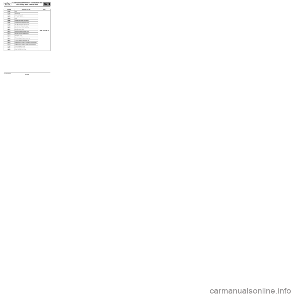
Tool fault Diagnostic tool title Vdiag
DF001UCH
44, 48, 4C, 4D, 4F, 50 DF002Steering lock
DF003Clutch switch circuit'
DF004Brake light switch circuit
DF005Card
DF006Front left-hand wheel valve sensor
DF007Front right-hand wheel valve sensor
DF008Rear right-hand wheel valve sensor
DF009Rear left-hand wheel valve sensor
DF010Steering column control unit circuit
DF011Rain/light sensor circuit
DF012Right-hand direction indicator circuit
DF013Left-hand direction indicator circuit
DF014Card reader circuit
DF015Optical sensor circuit
DF016At least 2 identical codes/summer set
DF017At least 2 identical codes/winter set
DF018Programming of 4 codes in summer set not performed
DF019Programming of 4 codes in winter set not performed
DF020Front internal aerial circuit
DF021Rear internal aerial circuit
DF022Centre internal aerial circuit
MR-372-J84-87B000$258.mif
Page 76 of 391

PASSENGER COMPARTMENT CONNECTION UNIT
Fault finding - Interpretation of faults
87B
87B-76
PASSENGER COMPARTMENT CONNECTION UNIT
Fault finding - Interpretation of faults
87B
87B-76V9 MR-372-J84-87B000$301.mif
UCH
Vdiag No.: 44, 48,
4C, 4D, 4F, 50
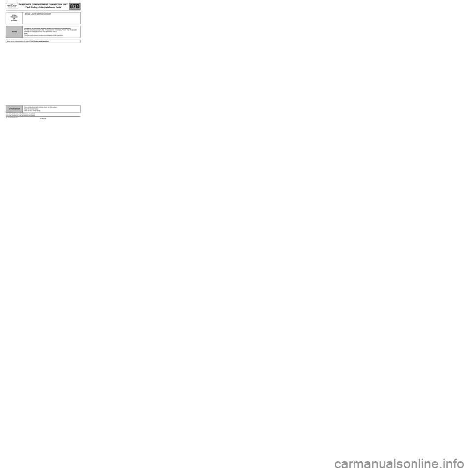
DF004
PRESENT
OR
STOREDBRAKE LIGHT SWITCH CIRCUIT
NOTESConditions for applying the fault finding procedure to a stored fault:
The fault becomes present after 10 successive transitions of more than 1 second
between the released status and depressed status.
Note:
The fault could prevent cruise control/speed limiter operation.
Refer to the interpretation of status ET047 Brake pedal position.
AFTER REPAIRCarry out another fault finding check on the system.
Clear the stored faults.
Deal with any other faults.
UCH_V44_DF004 /UCH_V48_DF004/UCH_V4C_DF004/
UCH_V4D_DF004/UCH_V4F_DF004/UCH_V50_DF004
Page 167 of 391

PASSENGER COMPARTMENT CONNECTION UNIT
Fault finding - Interpretation of statuses
87B
87B -167
PASSENGER COMPARTMENT CONNECTION UNIT
Fault finding - Interpretation of statuses
87B
87B -167V9 MR-372-J84-87B000$473.mif
UCH
Vdiag No.: 44, 48,
4C, 4D, 4F, 50
ET047
CONTINUED 1
ET047 Undetermined without depressing the pedal.
Check the condition and connection of the brake pedal switch connector.
If the connector is faulty and if there is a repair method (see Technical Note 6015A, Repairing electrical wiring,
Wiring: Precautions for repair), repair the connector; otherwise, replace the wiring.
Check for + 12 V on connection BPT of component 160.
If not correct:
–Check the condition and connection UCH connectorPP3. If the connector is faulty and if there is a repair method
(see Technical Note 6015A, Repairing electrical wiring, Wiring: Precautions for repair), repair the
connector; otherwise, replace the wiring.
–With the UCH and the brake pedal switch disconnected, check the insulation in relation to earth and the
continuity of the following connection:
●Connection code BPT between components 645 and 160.
If the connection is faulty and if there is a repair procedure (see Technical Note 6015A, Electrical wiring repair,
Wiring: Precautions for repair), repair the wiring, otherwise replace the wiring.
Remove the brake pedal switch and check the continuity between connections BPT and 5A of component 160
(switch piston pressed).
Only replace the brake pedal switch if it is not correct.
Check the condition and connection of the UCH connector PE2.
If the connector is faulty and if there is a repair method (see Technical Note 6015A, Repairing electrical wiring,
Wiring: Precautions for repair), repair the connector; otherwise, replace the wiring.
With the UCH and brake light switch disconnected:
Check the insulation and continuity of the following connection:
●Connection code 5A, between components 645 and 160.
If the connection is faulty and there is a repair procedure (see Technical Note 6015A, Electrical wiring repair,
Wiring: Precautions for repair), repair the wiring, otherwise replace it.
The line is shared with the injection computer and the automatic transmission computer (if the vehicle is fitted with
an automatic transmission).
In the event of faulty insulation, it is therefore necessary, using a wiring diagram, to check the connections between
the brake pedal switch connector and these computers.
If the fault is still present, contact the Techline.
AFTER REPAIRCarry out another fault finding check on the system.
Clear the stored faults.
Deal with any other faults.
Page 168 of 391

PASSENGER COMPARTMENT CONNECTION UNIT
Fault finding - Interpretation of statuses
87B
87B -168
PASSENGER COMPARTMENT CONNECTION UNIT
Fault finding - Interpretation of statuses
87B
87B -168V9 MR-372-J84-87B000$473.mif
UCH
Vdiag No.: 44, 48,
4C, 4D, 4F, 50
ET047
CONTINUED 2
ET047 Inconsistency without depressing the pedal.
Check the condition and connection of the brake pedal switch connector.
If the connector is faulty and if there is a repair method (see Technical Note 6015A, Repairing electrical wiring,
Wiring: Precautions for repair), repair the connector; otherwise, replace the wiring.
With the brake pedal switch disconnected:
Check the insulation between connections 65A and SP17 of component 160 (brake light switch piston pressed).
Only replace the brake pedal switch if it is not correct.
Check the condition and connection of the UCH connector PE2.
If the connector is faulty and if there is a repair method (see Technical Note 6015A, Repairing electrical wiring,
Wiring: Precautions for repair), repair the connector; otherwise, replace the wiring.
With the UCH and brake pedal switch disconnected:
Check the insulation in relation to + 12 V of connection 5A between components 645 and 160.
The line is shared with the ABS computer or the electronic stability program (ESP) relay (depending on equipment)
and the brake lights.
In the event of faulty insulation, use a wiring diagram to check the connections between the brake pedal switch
connector and these components.
If the fault is still present, contact the Techline.
AFTER REPAIRCarry out another fault finding check on the system.
Clear the stored faults.
Deal with any other faults.
Page 169 of 391

PASSENGER COMPARTMENT CONNECTION UNIT
Fault finding - Interpretation of statuses
87B
87B -169
PASSENGER COMPARTMENT CONNECTION UNIT
Fault finding - Interpretation of statuses
87B
87B -169V9 MR-372-J84-87B000$473.mif
UCH
Vdiag No.: 44, 48,
4C, 4D, 4F, 50
ET047
CONTINUED 3
ET047 Undetermined with the pedal depressed.
Check the condition and connection of the brake pedal switch connector.
If the connector is faulty and if there is a repair method (see Technical Note 6015A, Repairing electrical wiring,
Wiring: Precautions for repair), repair the connector; otherwise, replace the wiring.
With the brake pedal switch disconnected:
Check for + 12 V on component 160 on connection SP17.
If not correct:
–Check the condition and connection of fuse 1H in the passenger compartment relay and fuse box.
–Check the condition and the connection of the passenger compartment fuse and relay box connector. If the
connector is faulty and if there is a repair method (see Technical Note 6015A, Repairing electrical wiring,
Wiring: Precautions for repair), repair the connector; otherwise, replace the wiring.
–Check the insulation and continuity of connection SP17 between components 160 and 260. If the connection
is faulty and there is a repair procedure (see Technical Note 6015A, Electrical wiring repair, Wiring:
Precautions for repair), repair the wiring, otherwise replace it.
If it is still faulty, contact Techline.
With the brake pedal switch disconnected:
Check the continuity of the following connections:
●Connection code 65A,
●Connection code SP17 of component 160 (brake pedal switch piston free).
Only replace the brake pedal switch if it is not correct.
Check the condition and connection of the UCH connector PE2.
If the connector is faulty and if there is a repair method (see Technical Note 6015A, Repairing electrical wiring,
Wiring: Precautions for repair), repair the connector; otherwise, replace the wiring.
With the UCH and brake pedal switch disconnected:
Check the insulation and continuity of the following connection:
●Connection code 65A between components 645 and 160.
If the connection is faulty and there is a repair procedure (see Technical Note 6015A, Electrical wiring repair,
Wiring: Precautions for repair), repair the wiring, otherwise replace it.
The line is shared with the ABS computer or the ESP relay (depending on equipment) and the brake lights. In the
event of faulty insulation, it is therefore necessary, using a wiring diagram, to check the connections between the
brake pedal switch connector and these components.
AFTER REPAIRCarry out another fault finding check on the system.
Clear the stored faults.
Deal with any other faults.
Page 373 of 391

PASSENGER COMPARTMENT CONNECTION UNIT
Fault finding - Fault Finding Chart
87B
87B -373
PASSENGER COMPARTMENT CONNECTION UNIT
Fault finding - Fault Finding Chart
87B
87B -373V9 MR-372-J84-87B000$989mif
UCH
Vdiag No.: 44, 48,
4C, 4D, 4F, 50
Manual gearbox
Automatic gearbox
ALP48 Erratic starting
NOTESOnly consult this customer complaint after a complete check with the diagnostic
tool.
Make sure that the clutch pedal switch is working correctly.
To do this, check the consistency of status ET048 Clutch pedal position in the UCH.
In the event of a problem, use the fault-finding procedure DF003 "Clutch switch circuit".
Make sure that the brake pedal switch is working correctly.
To do this, check the consistency of status ET047 Brake pedal position in the UCH.
In the event of a problem, use the fault-finding procedure DF004 "Brake light switch circuit".
Make sure that the gear selector lever is working correctly.
To do this, check the consistency of status ET005 Manual gearbox lever position in the Protection and Switching
Unit.
In the event of a fault, use the fault finding procedure for status ET005.
If the fault is still present, contact the Techline.
Make sure that the brake pedal switch is working correctly.
To do this, check the consistency of status ET047 Brake pedal position in the UCH.
In the event of a problem, use the fault-finding procedure DF004 "Brake light switch circuit".
Make sure that the clutch pedal switch is working correctly.
Particularly by checking the consistency of status ET108 Automatic transmission lever position in the UCH.
In the event of a fault, use fault finding procedure for status ET108.
If the fault is still present, contact the Techline.
AFTER REPAIRCarry out a complete check with the diagnostic tool.
UCH_V44_ALP48 /UCH_V48_ALP48/UCH_V4C_ALP48/
UCH_V4D_ALP48/UCH_V4F_ALP48/UCH_V50_ALP48