2008 RENAULT SCENIC wiring
[x] Cancel search: wiringPage 47 of 128

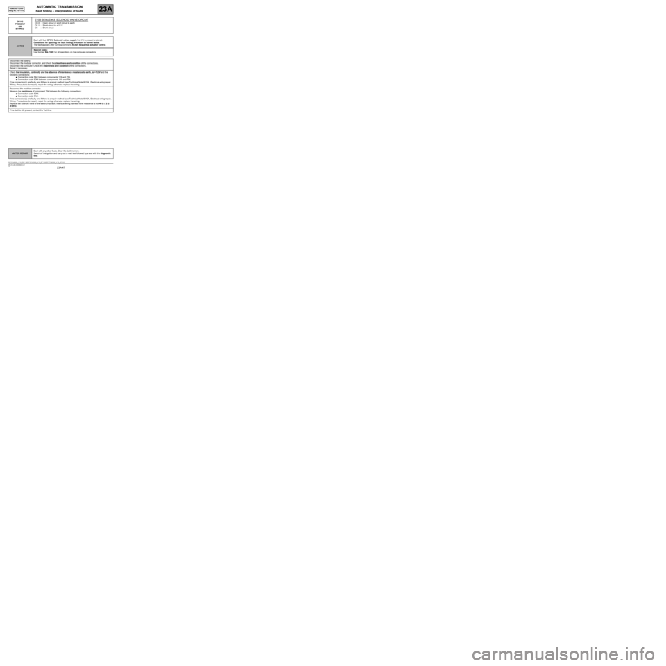
AUTOMATIC TRANSMISSION
Fault finding – Interpretation of faults23A
23A-47V4 MR-372-J84-23A050$330.mif
SIEMENS TA2000
Vdiag No.: 10-11-15
DF112
PRESENT
OR
STOREDEVS6 SEQUENCE SOLENOID VALVE CIRCUIT
CO.0 : Open circuit or short circuit to earth
CC.1 : Short-circuit to + 12 V
CC : Short circuit
NOTESDeal with fault DF012 Solenoid valves supply first if it is present or stored.
Conditions for applying the fault finding procedure to stored faults:
The fault appears after running command AC024 Sequential actuator control.
Special notes:
Use bornier Elé. 1681 for all operations on the computer connectors.
Disconnect the battery.
Disconnect the modular connector, and check the cleanliness and condition of the connections.
Disconnect the computer. Check the cleanliness and condition of the connections.
Repair if necessary.
Check the insulation, continuity and the absence of interference resistance to earth, to + 12 V and the
following connections:
●Connection code 5AU between components 119 and 754.
●Connection code 5DM between components 119 and 754.
If the connection(s) are faulty and if there is a repair method (see Technical Note 6015A, Electrical wiring repair,
Wiring: Precautions for repair), repair the wiring, otherwise replace the wiring.
Reconnect the modular connector.
Measure the resistance of component 754 between the following connections:
●Connection code 5DM.
●Connection code 5AU.
If the connection(s) are faulty and if there is a repair method (see Technical Note 6015A, Electrical wiring repair,
Wiring: Precautions for repair), repair the wiring, otherwise replace the wiring.
Replace the solenoid valve or the electric/hydraulic interface wiring harness if the resistance is not 40 ΩΩ Ω Ω
± 2 ΩΩ Ω Ω
at 20˚C.
If the fault is still present, contact the Techline.
AFTER REPAIRDeal with any other faults. Clear the fault memory.
Switch off the ignition and carry out a road test followed by a test with the diagnostic
tool.
DP0TA2000_V10_DF112/DP0TA2000_V11_DF112/DP0TA2000_V15_DF112
Page 55 of 128

AUTOMATIC TRANSMISSION
Fault finding – Interpretation of faults23A
23A-55V4 MR-372-J84-23A050$396.mif
SIEMENS TA2000
Vdiag No.: 10-11-15
DF126
PRESENT
OR
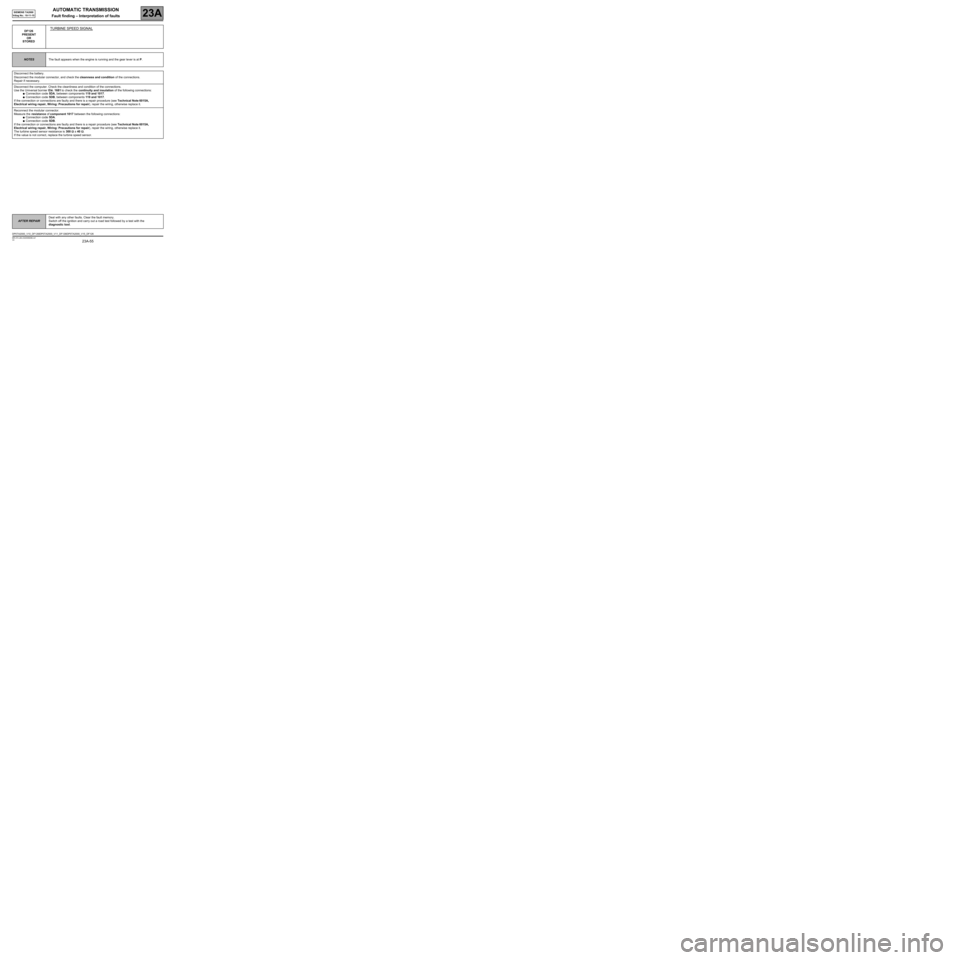
STOREDTURBINE SPEED SIGNAL
NOTESThe fault appears when the engine is running and the gear lever is at P.
Disconnect the battery.
Disconnect the modular connector, and check the cleanness and condition of the connections.
Repair if necessary.
Disconnect the computer. Check the cleanliness and condition of the connections.
Use the Universal bornier Elé. 1681 to check the continuity and insulation of the following connections:
●Connection code 5DA, between components 119 and 1017.
●Connection code 5DB, between components 119 and 1017.
If the connection or connections are faulty and there is a repair procedure (see Technical Note 6015A,
Electrical wiring repair, Wiring: Precautions for repair), repair the wiring, otherwise replace it.
Reconnect the modular connector.
Measure the resistance of component 1017 between the following connections:
●Connection code 5DA.
●Connection code 5DB.
If the connection or connections are faulty and there is a repair procedure (see Technical Note 6015A,
Electrical wiring repair, Wiring: Precautions for repair), repair the wiring, otherwise replace it.
The turbine speed sensor resistance is 300 ΩΩ Ω Ω
± 40 ΩΩ Ω Ω
.
If the value is not correct, replace the turbine speed sensor.
AFTER REPAIRDeal with any other faults. Clear the fault memory.
Switch off the ignition and carry out a road test followed by a test with the
diagnostic tool.
DP0TA2000_V10_DF126/DP0TA2000_V11_DF126/DP0TA2000_V15_DF126
Page 77 of 128

AUTOMATIC TRANSMISSION
Fault finding – Interpretation of statuses23A
23A-77V4 MR-372-J84-23A050$594.mif
SIEMENS TA2000
Vdiag No.: 10-11-15AUTOMATIC TRANSMISSION
Fault finding – Interpretation of statuses
ET001
SOLENOID VALVE SUPPLY
NOTESThere must be no present or stored faults.
Force the solenoid valves supply by running command AC024 Sequential actuator control (see Interpretation
of commands).
Disconnect the electric/hydraulic interface connector and check:
●Check for earth on connection 5AU of component 757.
●Check for earth on connection 5DN of component 1019.
●Check for earth on connection 5AZ of component 754.
If the connection or connections are faulty and there is a repair procedure (see Technical Note 6015A, Electrical
wiring repair, Wiring: Precautions for repair), repair the wiring, otherwise replace it.
The solenoid valves feed status is PRESENT at a voltage of + 12 V.
If the status is not correct, apply the interpretation of fault DF012 Solenoid valves supply.
Repair if necessary.
AFTER REPAIRRepeat the conformity check from the start.
DP0TA2000_V10_ET001/DP0TA2000_V11_ET001/DP0TA2000_V15_ET001
MR-372-J84-23A050$594.mif
Page 78 of 128

AUTOMATIC TRANSMISSION
Fault finding – Interpretation of statuses23A
23A-78V4 MR-372-J84-23A050$594.mif
SIEMENS TA2000
Vdiag No.: 10-11-15
ET003
BRAKE LIGHT SWITCH (OPENING)
NOTESThere must be no present or stored faults.
The status displays OPEN with the pedal released and changes to CLOSED with the brake pedal depressed.
Check the cleanliness and the condition of the brake light switch connections.
Check the positioning, setting and correct operation of the brake light switch (Pay attention to the floor carpet which
can block the switch).
Disconnect the battery.
Disconnect the computer. Check the cleanliness and condition of the connections.
Use the Universal bornier Elé. 1681 to check the insulation, continuity and the absence of interference resistance
on the following connection:
●Connection code 5A, between components 119 and 160.
If the connection is faulty and there is a repair procedure (see Technical Note 6015A, Electrical wiring repair,
Wiring: Precautions for repair), repair the wiring, otherwise replace it.
If the correct status is not displayed, replace the switch.
AFTER REPAIRRepeat the conformity check from the start.
DP0TA2000_V10_ET003/DP0TA2000_V11_ET003/DP0TA2000_V15_ET003
Page 79 of 128

AUTOMATIC TRANSMISSION
Fault finding – Interpretation of statuses23A
23A-79V4 MR-372-J84-23A050$594.mif
SIEMENS TA2000
Vdiag No.: 10-11-15
ET004
STOP LIGHT SWITCH (CLOSURE)
NOTESThere must be no present or stored faults.
The status displays CLOSED with the pedal released and changes to OPEN with the brake pedal depressed.
Check the cleanliness and the condition of the brake light switch connections.
Check the positioning, setting and correct operation of the brake light switch (Pay attention to the floor carpet
which can block the switch).
Disconnect the battery.
Disconnect the computer. Check the cleanliness and condition of the connections.
Use the Universal bornier Elé. 1681 to check the insulation, continuity and the absence of interference
resistance on the following connection:
●Connection code 5A, between components 119 and 160.
If the connection is faulty and there is a repair procedure (see Technical Note 6015A, Electrical wiring repair,
Wiring: Precautions for repair), repair the wiring, otherwise replace it.
Repair if necessary.
If the correct status is not displayed, replace the switch.
AFTER REPAIRRepeat the conformity check from the start.
DP0TA2000_V10_ET004/DP0TA2000_V11_ET004/DP0TA2000_V15_ET004
Page 81 of 128

AUTOMATIC TRANSMISSION
Fault finding – Interpretation of statuses23A
23A-81V4 MR-372-J84-23A050$594.mif
SIEMENS TA2000
Vdiag No.: 10-11-15
ET012
GEAR LEVER POSITION
NOTESThere must be no present or stored faults.
SIDE LEVER
"P"-"R"- "N"-"D"
Check the cleanliness, condition and mounting of the automatic transmission
multifunction switch.
Check the control setting (see MR 370 Mechanical, 23A Automatic transmission,
Multifunction switch, Adjustment (for Mégane II and Scénic II)).
Disconnect the battery.
Disconnect the modular connector and check the cleanliness and condition
of the connector A connections.
If one of the connectors is faulty and there is a repair method (see Technical Note
6015A, Electrical wiring repair, wiring: precautions for repair), repair the connector,
otherwise replace the wiring.
Check the continuity of the following connections:
Lever in position P
●Connection codes 5DG and 5DK between components 119 and 485.
Lever in position R
●Connection codes 5DG, 5DH, DJ et 5DK between components 119 and 485.
Lever in position N
●Connection code 5DH between components 119 and 485.
Lever in position D
●Connection code 5DJ between components 119 and 485.
Check the insulation from + 12 V of the following connections:
Lever in position P
●Connection codes 5DH, 5DJ and 5DK between components 119 and 485.
Lever in position N
●Connection codes 5DH, 5DJ and 5DK between components 119 and 485.
Lever in position D
●Connection codes 5DG, 5DH and 5DK between components 119 and 485.
If the connection or connections are faulty and there is a repair procedure
(see Technical Note 6015A, Electrical wiring repair, Wiring: Precautions for
repair), repair the wiring, otherwise replace it.
AFTER REPAIRRepeat the conformity check from the start.
DP0TA2000_V10_ET012/DP0TA2000_V11_ET012/DP0TA2000_V15_ET012
Page 82 of 128

AUTOMATIC TRANSMISSION
Fault finding – Interpretation of statuses23A
23A-82V4 MR-372-J84-23A050$594.mif
SIEMENS TA2000
Vdiag No.: 10-11-15
ET012
CONTINUED
SIDE LEVER
"P"-"R"- "N"-"D"
(continued)
LEVER POSITION
M, M+ AND M-
incremental shift
Disconnect the multifunction switch.
Use the universal bornier Elé. 1681 to check the insulation, continuity and
the absence of interference resistance on the following connections:
●Connection code 5DG between components 119 and 485.
●Connection code 5DH between components 119 and 485.
●Connection code 5DJ between components 119 and 485.
●Connection code 5DK between components 119 and 485.
If the connection or connections are faulty and there is a repair procedure (see Technical
Note 6015A, Electrical wiring repair, Wiring: Precautions for repair), repair the wiring,
otherwise replace it.
Repair if necessary.
Check the cleanliness and the condition of the sequential lever module connections.
Disconnect the battery. Disconnect the computer.
Check the cleanliness and condition of the connections.
Use the Universal bornier Elé. 1681.
Check the insulation, continuity and absence of interference resistance
on the following connections:
●Connection code 5FM between components 119 and 129.
If the connection is faulty and there is a repair procedure (see Technical Note 6015A,
Electrical wiring repair, Wiring: Precautions for repair), repair the wiring, otherwise
replace it.
●Connection code 5H between components 119 and 129.
If the connection is faulty and there is a repair procedure (see Technical Note 6015A,
Electrical wiring repair, Wiring: Precautions for repair), repair the wiring, otherwise
replace it.
●Connection code N between components 129 and 107.
If the connection is faulty and there is a repair procedure (see Technical Note 6015A,
Electrical wiring repair, Wiring: Precautions for repair), repair the wiring, otherwise
replace it.
Repair if necessary.
AFTER REPAIRRepeat the conformity check from the start.
Page 85 of 128

AUTOMATIC TRANSMISSION
Fault finding – Interpretation of statuses23A
23A-85V4 MR-372-J84-23A050$594.mif
SIEMENS TA2000
Vdiag No.: 10-11-15
ET021
SEQUENCE SOLENOID VALVE 1 CONTROL
NOTESThere must be no present or stored faults.
This status displays ACTIVE when the gear engaged is 3 or 4 and INACTIVE when other gears are engaged.
Disconnect the computer. Check the cleanliness and condition of the connectors.
Check the continuity between track 10 of the computer connector and track B8 of the modular connector.
Check the continuity of the following connections:
●Connection code 5AV between components 119 and 754.
If the connection is faulty and there is a repair procedure (see Technical Note 6015A, Electrical wiring repair,
Wiring: Precautions for repair), repair the wiring, otherwise replace it.
Measure the resistance of component 754 between the following connections:
●Connection code 5AV.
●Connection code 5AU.
The value should be 40 ΩΩ Ω Ω
± 2 ΩΩ Ω Ω
at approximately 20˚C.
Repair if necessary.
If the connection or connections are faulty and there is a repair procedure (see Technical Note 6015A, Electrical
wiring repair, Wiring: Precautions for repair), repair the wiring, otherwise replace it.
If the resistance is greater than 50 ΩΩ Ω Ω
, check the wiring harness, computer connector and modular connector.
Reconnect the computer.
Activate the solenoid valves with command AC024 Actuator sequential control and measure the current
in the solenoid valves.
If the current is 250 mA, the solenoid valve is working properly.
If the current is weaker, check the computer connections and harness up to the solenoid valve.
If the status does not function as specified, use the interpretation of fault DF085 EVS1 Sequence solenoid valve
circuit.
If the fault is still present, replace the electric/hydraulic interface.
AFTER REPAIRRepeat the conformity check from the start.
Make sure that shifting up and down through each gear works properly.
DP0TA2000_V10_ET021/DP0TA2000_V11_ET021/DP0TA2000_V15_ET021