Page 22 of 2771
AT-10
< SERVICE INFORMATION >
PREPARATION
PREPARATION
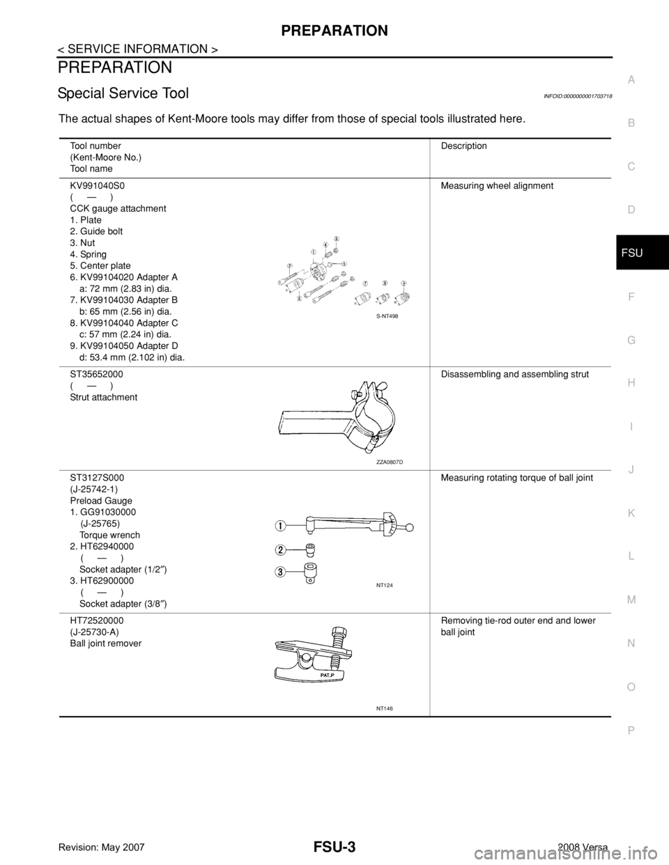
Special Service ToolINFOID:0000000001703156
The actual shapes of Kent-Moore tools may differ from those of special service tools illustrated here.
Tool number
(Kent-Moore No.)
Tool nameDescription
ST2505S001
(J-34301)
Oil pressure gauge set
1. ST25051001
(J-34301)
Oil pressure gauge
2. ST25052000
(J-34301)
Hose
3. ST25053000
(J-25695-3)
Joint pipe
4. ST25054000
(J-25695-4)
Adapter
5. ST25055000
(J-25695-5)
AdapterMeasuring line pressure
ST35325000
( — )
DriftInstalling LH differential side oil seal
(Use with KV31103000)
a: 215 mm (8.46 in)
b: 25 mm (0.98 in) dia.
c: M12 X 1.5P
KV31103000
(J-38982)
DriftInstalling LH differential side oil seal
(Use with ST35325000)
a: 59 mm (2.32 in) dia.
b: 49 mm (1.93 in) dia.
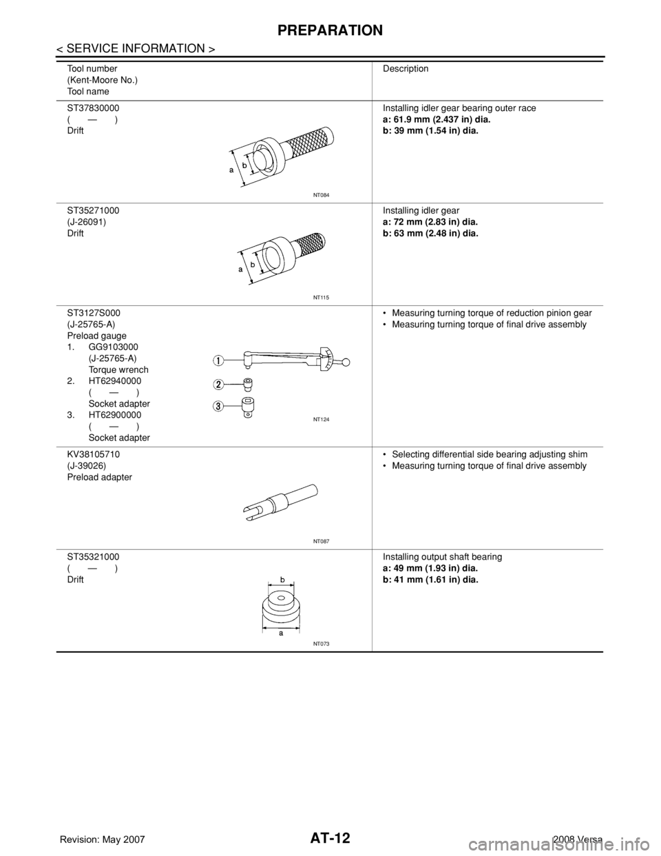
ST37830000
( — )
DriftInstalling idler gear bearing outer race
a: 61.9 mm (2.437 in) dia.
b: 39 mm (1.54 in) dia.
ST27180001
(J-25726-A)
PullerRemoving idler gear
a: 100 mm (3.94 in)
b: 110 mm (4.33 in)
c: M8 X 1.25P
NT097
SCIA7102E
SCIA7103E
NT084
NT424
Page 24 of 2771
AT-12
< SERVICE INFORMATION >
PREPARATION
ST37830000
( — )
DriftInstalling idler gear bearing outer race
a: 61.9 mm (2.437 in) dia.
b: 39 mm (1.54 in) dia.
ST35271000
(J-26091)
DriftInstalling idler gear
a: 72 mm (2.83 in) dia.
b: 63 mm (2.48 in) dia.
ST3127S000
(J-25765-A)
Preload gauge
1. GG9103000
(J-25765-A)
Torque wrench
2. HT62940000
( — )
Socket adapter
3. HT62900000
( — )
Socket adapter• Measuring turning torque of reduction pinion gear
• Measuring turning torque of final drive assembly
KV38105710
(J-39026)
Preload adapter• Selecting differential side bearing adjusting shim
• Measuring turning torque of final drive assembly
ST35321000
( — )
DriftInstalling output shaft bearing
a: 49 mm (1.93 in) dia.
b: 41 mm (1.61 in) dia. Tool number
(Kent-Moore No.)
Tool nameDescription
NT084
NT115
NT124
NT087
NT073
Page 236 of 2771
AT-224
< SERVICE INFORMATION >
ON-VEHICLE SERVICE
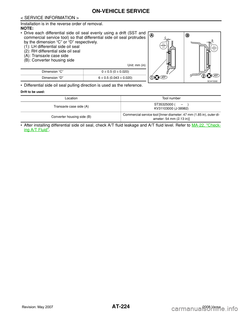
Installation is in the reverse order of removal.
NOTE:
• Drive each differential side oil seal evenly using a drift (SST and
commercial service tool) so that differential side oil seal protrudes
by the dimension “C” or “D” respectively.
(1): LH differential side oil seal
(2): RH differential side oil seal
(A): Transaxle case side
(B): Converter housing side
Unit: mm (in)
• Differential side oil seal pulling direction is used as the reference.
Drift to be used:
• After installing differential side oil seal, check A/T fluid leakage and A/T fluid level. Refer to MA-22, "Check-
ing A/T Fluid".
Dimension “C” 0 ± 0.5 (0 ± 0.020)
Dimension “D” 6 ± 0.5 (0.043 ± 0.020)
SCIA7226E
Location Tool number
Transaxle case side (A)ST35325000 ( – )
KV31103000 (J-38982)
Converter housing side (B)Commercial service tool [Inner diameter: 47 mm (1.85 in), outer di-
ameter: 54 mm (2.13 in)]
Page 330 of 2771
AT-318
< SERVICE INFORMATION >
ASSEMBLY
ASSEMBLY
Assembly (1)INFOID:0000000001703391
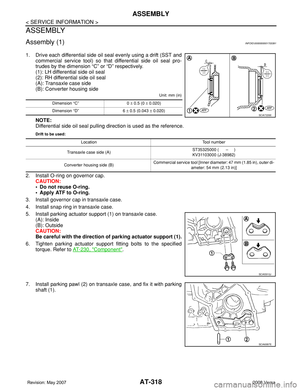
1. Drive each differential side oil seal evenly using a drift (SST and
commercial service tool) so that differential side oil seal pro-
trudes by the dimension “C” or “D” respectively.
(1): LH differential side oil seal
(2): RH differential side oil seal
(A): Transaxle case side
(B): Converter housing side
Unit: mm (in)
NOTE:
Differential side oil seal pulling direction is used as the reference.
Drift to be used:
2. Install O-ring on governor cap.
CAUTION:
• Do not reuse O-ring.
• Apply ATF to O-ring.
3. Install governor cap in transaxle case.
4. Install snap ring in transaxle case.
5. Install parking actuator support (1) on transaxle case.
(A): Inside
(B): Outside
CAUTION:
Be careful with the direction of parking actuator support (1).
6. Tighten parking actuator support fitting bolts to the specified
torque. Refer to AT-230, "
Component".
7. Install parking pawl (2) on transaxle case, and fix it with parking
shaft (1).
Dimension “C” 0 ± 0.5 (0 ± 0.020)
Dimension “D” 6 ± 0.5 (0.043 ± 0.020)
SCIA7226E
Location Tool number
Transaxle case side (A)ST35325000 ( – )
KV31103000 (J-38982)
Converter housing side (B)Commercial service tool [Inner diameter: 47 mm (1.85 in), outer di-
ameter: 54 mm (2.13 in)]
SCIA5910J
SCIA6997E
Page 1685 of 2771
EM-8
< SERVICE INFORMATION >
PREPARATION
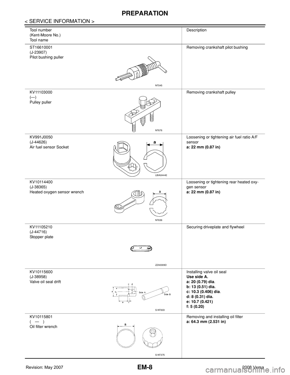
ST16610001
(J-23907)
Pilot bushing pullerRemoving crankshaft pilot bushing
KV11103000
(—)
Pulley pullerRemoving crankshaft pulley
KV991J0050
(J-44626)
Air fuel sensor SocketLoosening or tightening air fuel ratio A/F
sensor
a: 22 mm (0.87 in)
KV10114400
(J-38365)
Heated oxygen sensor wrenchLoosening or tightening rear heated oxy-
gen sensor
a: 22 mm (0.87 in)
KV11105210
(J-44716)
Stopper plateSecuring driveplate and flywheel
KV10115600
(J-38958)
Valve oil seal driftInstalling valve oil seal
Use side A.
a: 20 (0.79) dia.
b: 13 (0.51) dia.
c: 10.3 (0.406) dia.
d: 8 (0.31) dia.
e: 10.7 (0.421)
f: 5 (0.20)
KV10115801
(—)
Oil filter wrenchRemoving and installing oil filter
a: 64.3 mm (2.531 in) Tool number
(Kent-Moore No.)
Tool nameDescription
NT045
NT676
LBIA0444E
NT636
ZZA0009D
S-NT603
S-NT375
Page 1716 of 2771
TIMING CHAIN
EM-39
< SERVICE INFORMATION >
C
D
E
F
G
H
I
J
K
L
MA
EM
N
P O
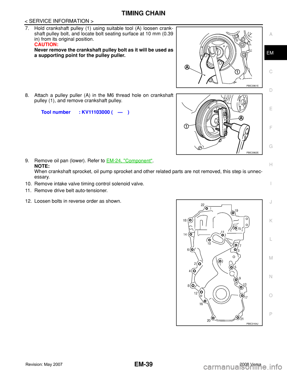
7. Hold crankshaft pulley (1) using suitable tool (A) loosen crank-
shaft pulley bolt, and locate bolt seating surface at 10 mm (0.39
in) from its original position.
CAUTION:
Never remove the crankshaft pulley bolt as it will be used as
a supporting point for the pulley puller.
8. Attach a pulley puller (A) in the M6 thread hole on crankshaft
pulley (1), and remove crankshaft pulley.
9. Remove oil pan (lower). Refer to EM-24, "
Component".
NOTE:
When crankshaft sprocket, oil pump sprocket and other related parts are not removed, this step is unnec-
essary.
10. Remove intake valve timing control solenoid valve.
11. Remove drive belt auto-tensioner.
12. Loosen bolts in reverse order as shown.
PBIC3961E
Tool number : KV11103000 ( — )
PBIC3962E
PBIC3164J
Page 1837 of 2771
PREPARATION
FSU-3
< SERVICE INFORMATION >
C
D
F
G
H
I
J
K
L
MA
B
FSU
N
O
P
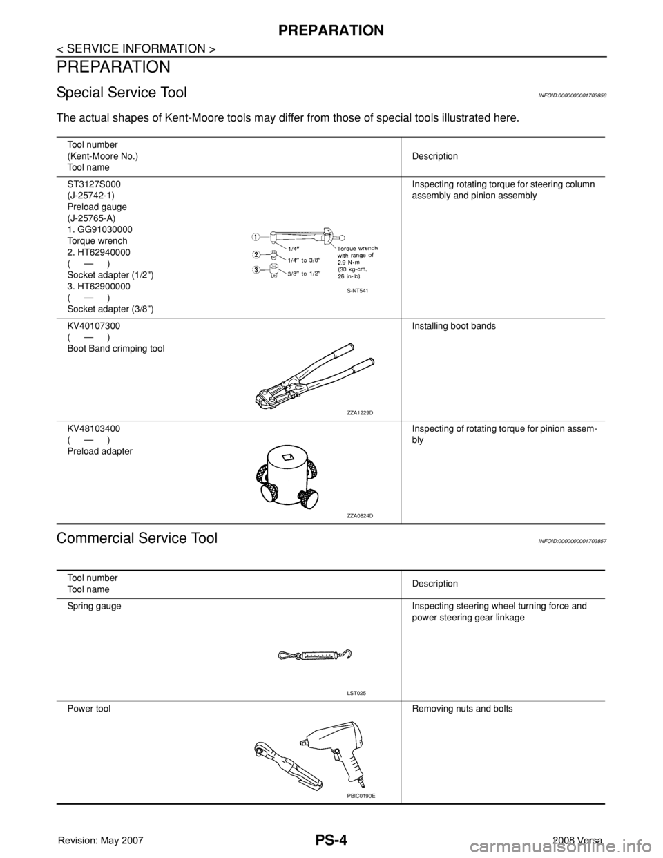
PREPARATION
Special Service ToolINFOID:0000000001703718
The actual shapes of Kent-Moore tools may differ from those of special tools illustrated here.
Tool number
(Kent-Moore No.)
Tool nameDescription
KV991040S0
(—)
CCK gauge attachment
1. Plate
2. Guide bolt
3. Nut
4. Spring
5. Center plate
6. KV99104020 Adapter A
a: 72 mm (2.83 in) dia.
7. KV99104030 Adapter B
b: 65 mm (2.56 in) dia.
8. KV99104040 Adapter C
c: 57 mm (2.24 in) dia.
9. KV99104050 Adapter D
d: 53.4 mm (2.102 in) dia.Measuring wheel alignment
ST35652000
(—)
Strut attachmentDisassembling and assembling strut
ST3127S000
(J-25742-1)
Preload Gauge
1. GG91030000
(J-25765)
Torque wrench
2. HT62940000
( — )
Socket adapter (1/2″)
3. HT62900000
( — )
Socket adapter (3/8″)Measuring rotating torque of ball joint
HT72520000
(J-25730-A)
Ball joint removerRemoving tie-rod outer end and lower
ball joint
S-NT498
ZZA0807D
NT124
NT146
Page 2510 of 2771
PS-4
< SERVICE INFORMATION >
PREPARATION
PREPARATION
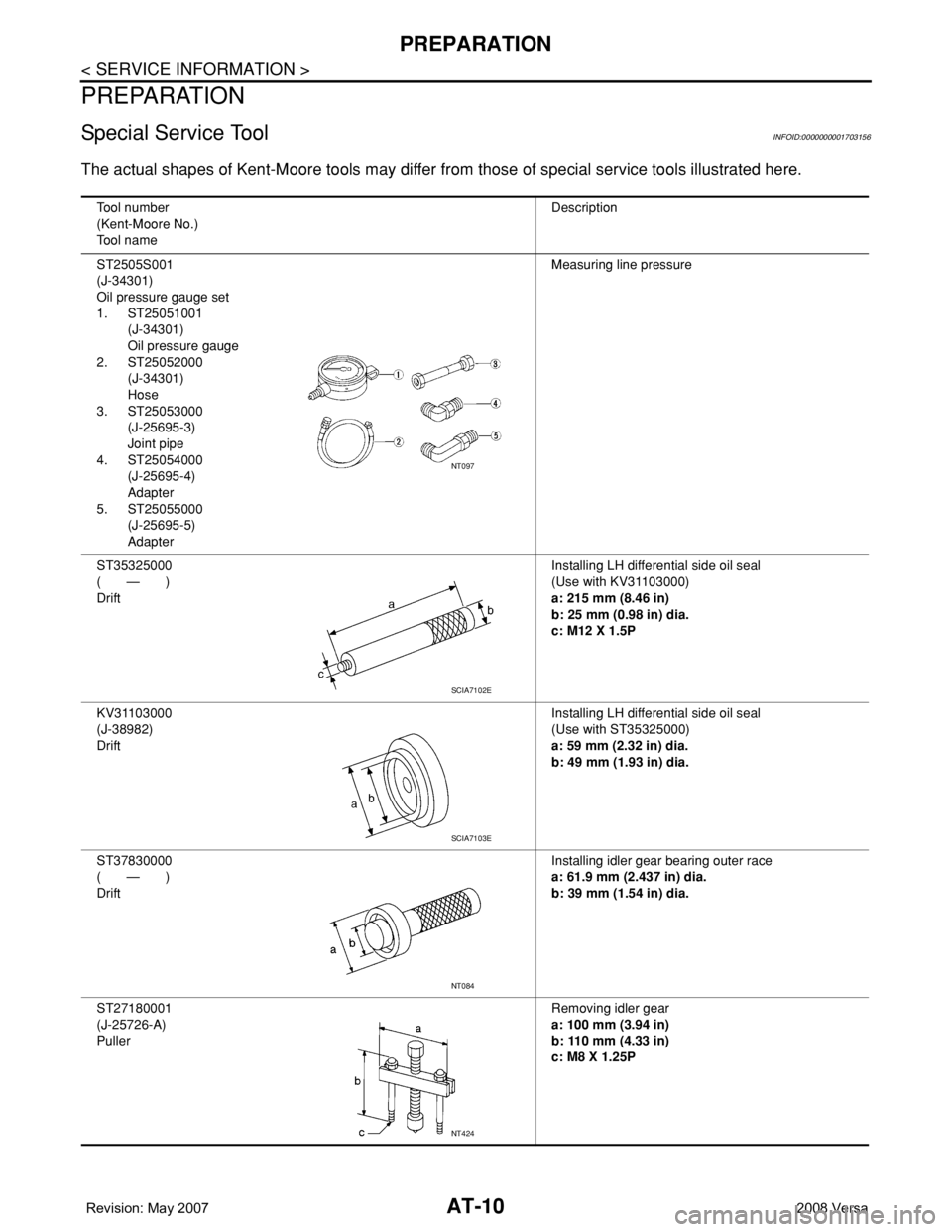
Special Service ToolINFOID:0000000001703856
The actual shapes of Kent-Moore tools may differ from those of special tools illustrated here.
Commercial Service ToolINFOID:0000000001703857
Tool number
(Kent-Moore No.)
Tool nameDescription
ST3127S000
(J-25742-1)
Preload gauge
(J-25765-A)
1. GG91030000
Torque wrench
2. HT62940000
(—)
Socket adapter (1/2")
3. HT62900000
(—)
Socket adapter (3/8")Inspecting rotating torque for steering column
assembly and pinion assembly
KV40107300
(—)
Boot Band crimping toolInstalling boot bands
KV48103400
(—)
Preload adapterInspecting of rotating torque for pinion assem-
bly
S-NT541
ZZA1229D
ZZA0824D
Tool number
Tool nameDescription
Spring gauge Inspecting steering wheel turning force and
power steering gear linkage
Power toolRemoving nuts and bolts
LST025
PBIC0190E