2008 NISSAN TIIDA Engine
[x] Cancel search: EnginePage 1574 of 2771
 sensor 1 is a planar one-cell limit current sen-
sor.")
EC-500
< SERVICE INFORMATION >
DTC P2A00 A/F SENSOR 1
DTC P2A00 A/F SENSOR 1
Component DescriptionINFOID:0000000001703041
The air fuel ratio (A/F) sensor 1 is a planar one-cell limit current sen-
sor. The sensor element of the A/F sensor 1 is composed an elec-
trode layer, which transports ions. It has a heater in the element.
The sensor is capable of precise measurement = 1, but also in the
lean and rich range. Together with its control electronics, the sensor
outputs a clear, continuous signal throughout a wide range.
The exhaust gas components diffuse through the diffusion layer at
the sensor cell. An electrode layer is applied voltage, and this current
relative oxygen density in lean. Also this current relative hydrocar-
bon density in rich.
Therefore, the A/F sensor 1 is able to indicate air fuel ratio by this
electrode layer of current. In addition, a heater is integrated in the
sensor to ensure the required operating temperature of about 800°C
(1,472°F).
CONSULT-II Reference Value in Data Monitor ModeINFOID:0000000001703042
Specification data are reference values.
On Board Diagnosis LogicINFOID:0000000001703043
To judge the malfunction, the A/F signal computed by ECM from the A/F sensor 1 signal is monitored not to be
shifted to LEAN side or RICH side.
DTC Confirmation ProcedureINFOID:0000000001703044
NOTE:
If DTC Confirmation Procedure has been previously conducted, always turn ignition switch OFF and wait at
least 10 seconds before conducting the next test.
TESTING CONDITION:
Before performing the following procedure, confirm that battery voltage is more than 11V at idle.
WITH CONSULT-II
1. Start engine and warm it up to normal operating temperature.
2. Turn ignition switch OFF and wait at least 10 seconds.
PBIB3353E
PBIB3354E
MONITOR ITEM CONDITION SPECIFICATION
A/F SEN1 (B1) • Engine: After warming upMaintaining engine speed at
2,000 rpmFluctuates around 2.2V
DTC No. Trouble diagnosis name DTC detecting condition Possible Cause
P2A00
2A00Air fuel ratio (A/F) sensor 1
circuit range/performance• The output voltage computed by ECM from the
A/F sensor 1 signal is shifted to the lean side for
a specified period.
• The A/F signal computed by ECM from the A/F
sensor 1 signal is shifted to the rich side for a
specified period.• Air fuel ratio (A/F) sensor 1
• Air fuel ratio (A/F) sensor 1 heater
• Fuel pressure
• Fuel injector
• Intake air leaks
Page 1575 of 2771

DTC P2A00 A/F SENSOR 1
EC-501
< SERVICE INFORMATION >
C
D
E
F
G
H
I
J
K
L
MA
EC
N
P O
3. Turn ignition switch ON and select “SELF-LEARNING CONT” in “WORK SUPPORT” mode with CON-
SULT-II.
4. Clear the self-learning coefficient by touching “CLEAR”.
5. Turn ignition switch OFF and wait at least 10 seconds.
6. Start engine and keep the engine speed between 3,500 and
4,000 rpm for 1 minute under no load.
7. Let engine idle for 1 minute.
8. Keep engine speed between 2,500 and 3,000 rpm for 20 min-
utes.
9. If 1st trip DTC is detected, go to EC-503, "
Diagnosis Procedure".
WITH GST
1. Start engine and warm it up to normal operating temperature.
2. Turn ignition switch OFF and wait at least 10 seconds.
3. Disconnect mass air flow sensor harness connector.
4. Start engine and let it idle for at least 5 seconds.
5. Stop engine and reconnect mass air flow sensor (1) harness
connector.
6. Select Service $03 with GST and make sure that DTC P0102 is
detected.
7. Select Service $04 with GST and erase the DTC P0102.
8. Start engine and keep the engine speed between 3,500 and
4,000 rpm for 1 minute under no load.
9. Let engine idle for 1 minute.
10. Keep engine speed between 2,500 and 3,000 rpm for 20 min-
utes.
11. Select Service $07 with GST.
If 1st trip DTC is detected, go to EC-503, "
Diagnosis Procedure".
PBIB2035E
BBIA0701E
Page 1577 of 2771
DTC P2A00 A/F SENSOR 1
EC-503
< SERVICE INFORMATION >
C
D
E
F
G
H
I
J
K
L
MA
EC
N
P O
Do not use ECM ground terminals when measuring input/output voltage. Doing so may result in dam-
age to the ECM's transistor. Use a ground other than ECM terminals, such as the ground.
: Average voltage for pulse signal (Actual pulse signal can be confirmed by oscilloscope.)
Diagnosis ProcedureINFOID:0000000001703046
1.CHECK GROUND CONNECTIONS
1. Turn ignition switch OFF.
2. Loosen and retighten ground screws on the body.
Refer to EC-142, "
Ground Inspection".
OK or NG
OK >> GO TO 2.
NG >> Repair or replace ground connections.
2.RETIGHTEN AIR FUEL RATIO (A/F) SENSOR 1
Loosen and retighten the air fuel ratio (A/F) sensor 1 (2).
• Air fuel ratio (A/F) sensor harness connector (1)
>> GO TO 3.
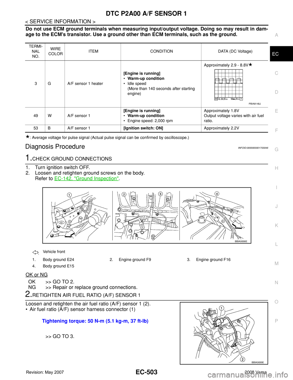
TERMI-
NAL
NO.WIRE
COLORITEM CONDITION DATA (DC Voltage)
3 G A/F sensor 1 heater[Engine is running]
•Warm-up condition
• Idle speed
(More than 140 seconds after starting
engine)Approximately 2.9 - 8.8V
49 W A/F sensor 1[Engine is running]
•Warm-up condition
• Engine speed: 2,000 rpmApproximately 1.8V
Output voltage varies with air fuel
ratio.
53 B A/F sensor 1[Ignition switch: ON]Approximately 2.2V
PBIA8148J
:Vehicle front
1. Body ground E24 2. Engine ground F9 3. Engine ground F16
4. Body ground E15
BBIA0698E
Tightening torque: 50 N-m (5.1 kg-m, 37 ft-lb)
BBIA0699E
Page 1578 of 2771

EC-504
< SERVICE INFORMATION >
DTC P2A00 A/F SENSOR 1
3.CHECK FOR INTAKE AIR LEAK
1. Start engine and run it at idle.
2. Listen for an intake air leak after the mass air flow sensor.
OK or NG
OK >> GO TO 4.
NG >> Repair or replace.
4.CLEAR THE SELF-LEARNING DATA
With CONSULT-II
1. Start engine and warm it up to normal operating temperature.
2. Select “SELF-LEARNING CONT” in “WORK SUPPORT” mode with CONSULT-II.
3. Clear the self-learning control coefficient by touching “CLEAR”.
4. Run engine for at least 10 minutes at idle speed.
Is the 1st trip DTC P0171 and P0172 detected?
Is it difficult to start engine?
Without CONSULT-II
1. Start engine and warm it up to normal operating temperature.
2. Turn ignition switch OFF.
3. Disconnect mass air flow sensor (1) harness connector.
4. Restart engine and let it idle for at least 5 seconds.
5. Stop engine and reconnect mass air flow sensor harness con-
nector.
6. Make sure DTC P0102 is displayed.
7. Erase the DTC memory. Refer to EC-47, "
Emission-related
Diagnostic Information".
8. Make sure DTC P0000 is displayed.
9. Run engine for at least 10 minutes at idle speed.
Is the 1st trip DTC P0171 and P0172 detected?
Is it difficult to start engine?
Ye s o r N o
Yes >> Perform trouble diagnosis for DTC P0171 or P0172. Refer to EC-257 or EC-264.
No >> GO TO 5.
5.CHECK HARNESS CONNECTOR
1. Turn ignition switch OFF.
2. Disconnect A/F sensor 1 harness connector (1).
- Air fuel ratio (A/F) sensor (2)
3. Check harness connector for water.
OK or NG
OK >> GO TO 6.
NG >> Repair or replace harness connector.
6.CHECK AIR FUEL RATIO (A/F) SENSOR 1 POWER SUPPLY CIRCUIT
1. Turn ignition switch ON.
PBIB2035E
BBIA0701E
Water should no exist.
BBIA0699E
Page 1580 of 2771
 sensor, clean exhaust system threads using Heated Oxygen
Sensor Thread Cleaner tool J-43897-18 or J")
EC-506
< SERVICE INFORMATION >
DTC P2A00 A/F SENSOR 1
• Before installing new air fuel ratio (A/F) sensor, clean exhaust system threads using Heated Oxygen
Sensor Thread Cleaner tool J-43897-18 or J-43897-12 and approved anti-seize lubricant.
>> GO TO 12.
12.CONFIRM A/F ADJUSTMENT DATA
1. Turn ignition switch ON.
2. Select “A/F ADJ-B1” in “DATA MONITOR” mode with CON-
SULT-II.
3. Make sure that “0.000” is displayed on CONSULT-II screen.
OK or NG
OK >>INSPECTION END
NG >> GO TO 13.
13.CLEAR THE SELF-LEARNGIN DATA
With CONSULT-II
1. Start engine and warm it up to normal operating temperature.
2. Select “SELF-LEARNING CONT” in “WORK SUPPORT” mode with CONSULT-II.
3. Clear the self-learning control coefficient by touching “CLEAR”.
Without CONSULT-II
1. Start engine and warm it up to normal operating temperature.
2. Turn ignition switch OFF.
3. Disconnect mass air flow sensor harness (1) connector.
4. Restart engine and let it idle for at least 5 seconds.
5. Stop engine and reconnect mass air flow sensor harness con-
nector.
6. Make sure DTC P0102 is displayed.
7. Erase the DTC memory. Refer to EC-47, "
Emission-related
Diagnostic Information".
8. Make sure DTC P0000 is displayed.
>> GO TO 14.
14.CONFIRM A/F ADJUSTMENT DATA
1. Turn ignition switch OFF and then ON.
PBIB3201E
PBIB2035E
BBIA0701E
Page 1595 of 2771

FUEL INJECTOR
EC-521
< SERVICE INFORMATION >
C
D
E
F
G
H
I
J
K
L
MA
EC
N
P O
FUEL INJECTOR
Component DescriptionINFOID:0000000001703059
The fuel injector is a small, precise solenoid valve. When the ECM
supplies a ground to the fuel injector circuit, the coil in the fuel injec-
tor is energized. The energized coil pulls the ball valve back and
allows fuel to flow through the fuel injector into the intake manifold.
The amount of fuel injected depends upon the injection pulse dura-
tion. Pulse duration is the length of time the fuel injector remains
open. The ECM controls the injection pulse duration based on
engine fuel needs.
CONSULT-II Reference Value in Data Monitor ModeINFOID:0000000001703060
Specification data are reference values.
PBIA9664J
MONITOR ITEM CONDITION SPECIFICATION
B/FUEL SCHDL See EC-127
.
INJ PULSE-B1• Engine: After warming up
• Air conditioner switch: OFF
• Shift lever: P or N (A/T, CVT),
Neutral (M/T)
•No loadIdle 2.0 - 3.0 msec
2,000 rpm 1.9 - 2.9 msec
Page 1597 of 2771

FUEL INJECTOR
EC-523
< SERVICE INFORMATION >
C
D
E
F
G
H
I
J
K
L
MA
EC
N
P O
Do not use ECM ground terminals when measuring input/output voltage. Doing so may result in dam-
age to the ECM's transistor. Use a ground other than ECM terminals, such as the ground.
: Average voltage for pulse signal (Actual pulse signal can be confirmed by oscilloscope.)
Diagnosis ProcedureINFOID:0000000001703062
1.INSPECTION START
Turn ignition switch to START.
Is any cylinder ignited?
Ye s o r N o
Yes >> GO TO 2.
No >> GO TO 3.
2.CHECK OVERALL FUNCTION
With CONSULT-II
1. Start engine.
2. Perform “POWER BALANCE” in “ACTIVE TEST” mode with
CONSULT-II.
3. Make sure that each circuit produces a momentary engine
speed drop.
Without CONSULT-II
1. Start engine.
TERMI-
NAL
NO.WIRE
COLORITEM CONDITION DATA (DC Voltage)
25
29
30
31V
Y
O
LFuel injector No. 4
Fuel injector No. 3
Fuel injector No. 2
Fuel injector No. 1[Engine is running]
•Warm-up condition
• Idle speed
NOTE:
The pulse cycle changes depending on rpm at
idleBATTERY VOLTAGE
(11 - 14V)
[Engine is running]
•Warm-up condition
• Engine speed: 2,000 rpmBATTERY VOLTAGE
(11 - 14V)
PBIB0529E
PBIA4943J
PBIB0133E
Page 1600 of 2771

EC-526
< SERVICE INFORMATION >
FUEL PUMP
FUEL PUMP
DescriptionINFOID:0000000001703065
SYSTEM DESCRIPTION
*: ECM determines the start signal status by the signals of engine speed and battery voltage.
The ECM activates the fuel pump for several seconds after the ignition switch is turned ON to improve engine
startability. If the ECM receives a engine speed signal from the crankshaft position sensor (POS) and cam-
shaft position sensor (PHASE), it knows that the engine is rotating, and causes the pump to operate. If the
engine speed signal is not received when the ignition switch is ON, the engine stalls. The ECM stops pump
operation and prevents battery discharging, thereby improving safety. The ECM does not directly drive the fuel
pump. It controls the ON/OFF fuel pump relay, which in turn controls the fuel pump.
COMPONENT DESCRIPTION
A turbine type design fuel pump is used in the fuel tank.
• Fuel level sensor unit and fuel pump (1)
• Fuel pressure regulator (2)
• Fuel level sensor (3)
• Fuel tank temperature sensor (4)
CONSULT-II Reference Value in Data Monitor ModeINFOID:0000000001703066
Specification data are reference values.
Sensor Input Signal to ECM ECM Function Actuator
Crankshaft position sensor (POS)
Camshaft position sensor (PHASE)Engine speed*
Fuel pump control Fuel pump relay
Battery Battery voltage*
Condition Fuel pump operation
Ignition switch is turned to ON Operates for 1 second
Engine running and crankingOperates
Engine: StoppedStops in 1.5 seconds
Except as shown aboveSt ops
BBIA0704E
MONITOR ITEM CONDITION SPECIFICATION
FUEL PUMP RLY• For 1 second after turning ignition switch ON
• Engine running or crankingON
• Except above conditions OFF