2008 NISSAN TIIDA warning lamps
[x] Cancel search: warning lampsPage 1112 of 2771

EC-38
< SERVICE INFORMATION >
ON BOARD REFUELING VAPOR RECOVERY (ORVR)
ON BOARD REFUELING VAPOR RECOVERY (ORVR)
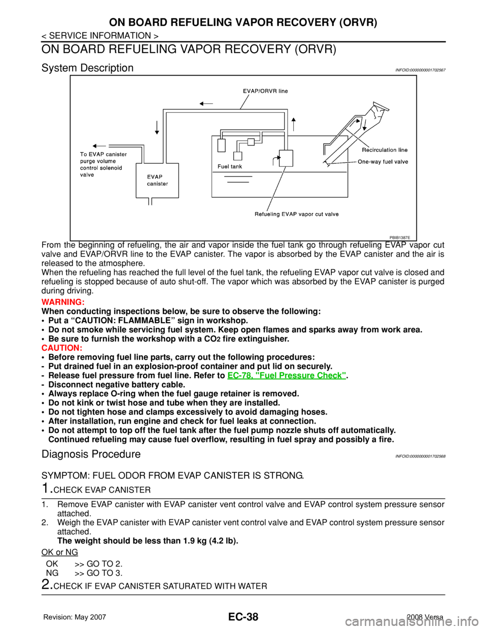
System DescriptionINFOID:0000000001702567
From the beginning of refueling, the air and vapor inside the fuel tank go through refueling EVAP vapor cut
valve and EVAP/ORVR line to the EVAP canister. The vapor is absorbed by the EVAP canister and the air is
released to the atmosphere.
When the refueling has reached the full level of the fuel tank, the refueling EVAP vapor cut valve is closed and
refueling is stopped because of auto shut-off. The vapor which was absorbed by the EVAP canister is purged
during driving.
WARNING:
When conducting inspections below, be sure to observe the following:
• Put a “CAUTION: FLAMMABLE” sign in workshop.
• Do not smoke while servicing fuel system. Keep open flames and sparks away from work area.
• Be sure to furnish the workshop with a CO
2 fire extinguisher.
CAUTION:
• Before removing fuel line parts, carry out the following procedures:
- Put drained fuel in an explosion-proof container and put lid on securely.
- Release fuel pressure from fuel line. Refer to EC-78, "
Fuel Pressure Check".
- Disconnect negative battery cable.
• Always replace O-ring when the fuel gauge retainer is removed.
• Do not kink or twist hose and tube when they are installed.
• Do not tighten hose and clamps excessively to avoid damaging hoses.
• After installation, run engine and check for fuel leaks at connection.
• Do not attempt to top off the fuel tank after the fuel pump nozzle shuts off automatically.
Continued refueling may cause fuel overflow, resulting in fuel spray and possibly a fire.
Diagnosis ProcedureINFOID:0000000001702568
SYMPTOM: FUEL ODOR FROM EVAP CANISTER IS STRONG.
1.CHECK EVAP CANISTER
1. Remove EVAP canister with EVAP canister vent control valve and EVAP control system pressure sensor
attached.
2. Weigh the EVAP canister with EVAP canister vent control valve and EVAP control system pressure sensor
attached.
The weight should be less than 1.9 kg (4.2 lb).
OK or NG
OK >> GO TO 2.
NG >> GO TO 3.
2.CHECK IF EVAP CANISTER SATURATED WITH WATER
PBIB1387E
Page 1824 of 2771

FL-4
< SERVICE INFORMATION >
FUEL SYSTEM
FUEL SYSTEM
Checking Fuel LineINFOID:0000000001703097
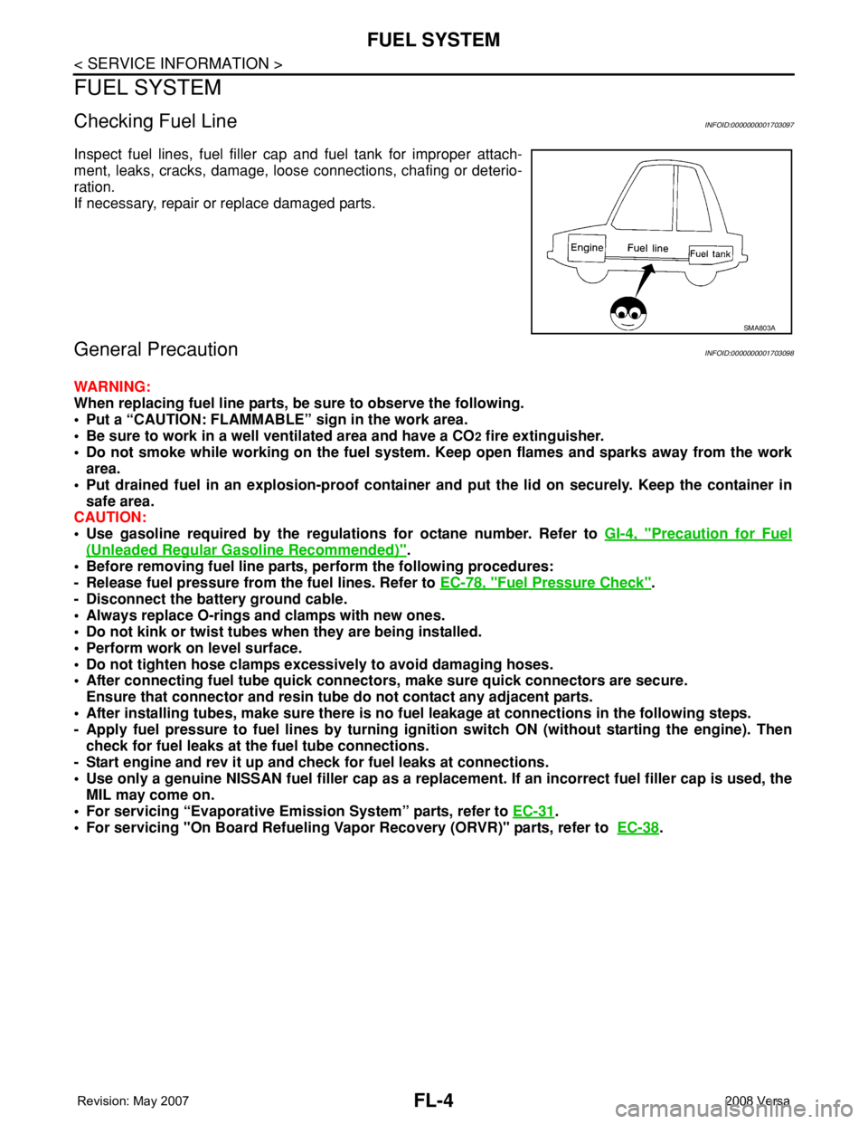
Inspect fuel lines, fuel filler cap and fuel tank for improper attach-
ment, leaks, cracks, damage, loose connections, chafing or deterio-
ration.
If necessary, repair or replace damaged parts.
General PrecautionINFOID:0000000001703098
WARNING:
When replacing fuel line parts, be sure to observe the following.
• Put a “CAUTION: FLAMMABLE” sign in the work area.
• Be sure to work in a well ventilated area and have a CO
2 fire extinguisher.
• Do not smoke while working on the fuel system. Keep open flames and sparks away from the work
area.
• Put drained fuel in an explosion-proof container and put the lid on securely. Keep the container in
safe area.
CAUTION:
• Use gasoline required by the regulations for octane number. Refer to GI-4, "
Precaution for Fuel
(Unleaded Regular Gasoline Recommended)".
• Before removing fuel line parts, perform the following procedures:
- Release fuel pressure from the fuel lines. Refer to EC-78, "
Fuel Pressure Check".
- Disconnect the battery ground cable.
• Always replace O-rings and clamps with new ones.
• Do not kink or twist tubes when they are being installed.
• Perform work on level surface.
• Do not tighten hose clamps excessively to avoid damaging hoses.
• After connecting fuel tube quick connectors, make sure quick connectors are secure.
Ensure that connector and resin tube do not contact any adjacent parts.
• After installing tubes, make sure there is no fuel leakage at connections in the following steps.
- Apply fuel pressure to fuel lines by turning ignition switch ON (without starting the engine). Then
check for fuel leaks at the fuel tube connections.
- Start engine and rev it up and check for fuel leaks at connections.
• Use only a genuine NISSAN fuel filler cap as a replacement. If an incorrect fuel filler cap is used, the
MIL may come on.
• For servicing “Evaporative Emission System” parts, refer to EC-31
.
• For servicing "On Board Refueling Vapor Recovery (ORVR)" parts, refer to EC-38
.
SMA803A
Page 2001 of 2771
![NISSAN TIIDA 2008 Service Repair Manual LAN-10
< FUNCTION DIAGNOSIS >[CAN FUNDAMENTAL]
TROUBLE DIAGNOSIS
Example: Data link connector branch line open circuit
NOTE:
• When data link connector branch line is open, transmission and receptio NISSAN TIIDA 2008 Service Repair Manual LAN-10
< FUNCTION DIAGNOSIS >[CAN FUNDAMENTAL]
TROUBLE DIAGNOSIS
Example: Data link connector branch line open circuit
NOTE:
• When data link connector branch line is open, transmission and receptio](/manual-img/5/57399/w960_57399-2000.png)
LAN-10
< FUNCTION DIAGNOSIS >[CAN FUNDAMENTAL]
TROUBLE DIAGNOSIS
Example: Data link connector branch line open circuit
NOTE:
• When data link connector branch line is open, transmission and reception of CAN communication signals
are not affected. Therefore, no symptoms occur. However, be sure to repair malfunctioning circuit.
• The model (all units on CAN communication system are Diag on CAN) cannot perform CAN diagnosis with
CONSULT-III if the following error occurs. The error is judged by the symptom.
EPS control unit Normal operation.
Combination meter• Shift position indicator and OD OFF indicator turn OFF.
• Warning lamps turn ON.
ABS actuator and electric unit (control unit) Normal operation.
TCM No impact on operation.
IPDM E/R Normal operation.Unit name Symptom
SKIB8739E
Unit name Symptom
ECM
Normal operation. BCM
EPS control unit
Combination meter
ABS actuator and electric unit (control unit)
TCM
IPDM E/R
Error Difference of symptom
Data link connector branch line open circuit Normal operation.
CAN-H, CAN-L harness short-circuitMost of the units which are connected to the CAN communication
system enter fail-safe mode or are deactivated.
Page 2002 of 2771
![NISSAN TIIDA 2008 Service Repair Manual TROUBLE DIAGNOSIS
LAN-11
< FUNCTION DIAGNOSIS >[CAN FUNDAMENTAL]
C
D
E
F
G
H
I
J
L
MA
B
LAN
N
O
P Example: Main Line Between Data Link Connector and ABS Actuator and Electric Unit (Control Unit) Open NISSAN TIIDA 2008 Service Repair Manual TROUBLE DIAGNOSIS
LAN-11
< FUNCTION DIAGNOSIS >[CAN FUNDAMENTAL]
C
D
E
F
G
H
I
J
L
MA
B
LAN
N
O
P Example: Main Line Between Data Link Connector and ABS Actuator and Electric Unit (Control Unit) Open](/manual-img/5/57399/w960_57399-2001.png)
TROUBLE DIAGNOSIS
LAN-11
< FUNCTION DIAGNOSIS >[CAN FUNDAMENTAL]
C
D
E
F
G
H
I
J
L
MA
B
LAN
N
O
P Example: Main Line Between Data Link Connector and ABS Actuator and Electric Unit (Control Unit) Open Circuit
Example: CAN-H, CAN-L Harness Short Circuit
SKIB8740E
Unit name Symptom
ECM Engine torque limiting is affected, and shift harshness increases.
BCM• Reverse warning chime does not sound.
• The front wiper moves under continuous operation mode even though the front wip-
er switch being in the intermittent position.
EPS control unit The steering effort increases.
Combination meter• The shift position indicator and OD OFF indicator turn OFF.
• The speedometer is inoperative.
• The odo/trip meter stops.
ABS actuator and electric unit (control unit) Normal operation.
TCM No impact on operation.
IPDM E/RWhen the ignition switch is ON,
• The headlamps (Lo) turn ON.
• The cooling fan continues to rotate.
SKIB8741E
Page 2003 of 2771
![NISSAN TIIDA 2008 Service Repair Manual LAN-12
< FUNCTION DIAGNOSIS >[CAN FUNDAMENTAL]
TROUBLE DIAGNOSIS
CAN Diagnosis with CONSULT-III
INFOID:0000000001711207
CAN diagnosis on CONSULT-III extracts the root cause by receiving the following NISSAN TIIDA 2008 Service Repair Manual LAN-12
< FUNCTION DIAGNOSIS >[CAN FUNDAMENTAL]
TROUBLE DIAGNOSIS
CAN Diagnosis with CONSULT-III
INFOID:0000000001711207
CAN diagnosis on CONSULT-III extracts the root cause by receiving the following](/manual-img/5/57399/w960_57399-2002.png)
LAN-12
< FUNCTION DIAGNOSIS >[CAN FUNDAMENTAL]
TROUBLE DIAGNOSIS
CAN Diagnosis with CONSULT-III
INFOID:0000000001711207
CAN diagnosis on CONSULT-III extracts the root cause by receiving the following information.
• Response to the system call
• Control unit diagnosis information
• Self-diagnosis
• CAN diagnostic support monitor
Self-DiagnosisINFOID:0000000001711208
CAN Diagnostic Support MonitorINFOID:0000000001711209
MONITOR ITEM (CONSULT-III)
Unit name Symptom
ECM• Engine torque limiting is affected, and shift harshness increases.
• Engine speed drops.
BCM• Reverse warning chime does not sound.
• The front wiper moves under continuous operation mode even though the front
wiper switch being in the intermittent position.
• The room lamp does not turn ON.
• The engine does not start (if an error or malfunction occurs while turning the igni-
tion switch OFF.)
• The steering lock does not release (if an error or malfunction occurs while turning
the ignition switch OFF.)
EPS control unit The steering effort increases.
Combination meter• The tachometer and the speedometer do not move.
• Warning lamps turn ON.
• Indicator lamps do not turn ON.
ABS actuator and electric unit (control unit) Normal operation.
TCM No impact on operation.
IPDM E/RWhen the ignition switch is ON,
• The headlamps (Lo) turn ON.
• The cooling fan continues to rotate.
DTCSelf-diagnosis item
(CONSULT-III indication)DTC detection condition Inspection/Action
U1000 CAN COMM CIRCUITWhen ECM is not transmitting or receiving CAN
communication signal of OBD (emission-related
diagnosis) for 2 seconds or more.
Start the inspection. Re-
fer to the applicable sec-
tion of the indicated
control unit. When a control unit (except for ECM) is not
transmitting or receiving CAN communication
signal for 2 seconds or more.
U1001 CAN COMM CIRCUITWhen ECM is not transmitting or receiving CAN
communication signal other than OBD (emis-
sion-related diagnosis) for 2 seconds or more.
U1002 SYSTEM COMMWhen a control unit is not transmitting or receiv-
ing CAN communication signal for 2 seconds or
less.
U1010 CONTROL UNIT [CAN]When an error is detected during the initial diag-
nosis for CAN controller of each control unit.Replace the control unit
indicating “U1010”.
Page 2138 of 2771

LT-1
ELECTRICAL
C
D
E
F
G
H
I
J
L
M
SECTION LT
A
B
LT
N
O
P
CONTENTS
LIGHTING SYSTEM
SERVICE INFORMATION ............................3
PRECAUTIONS ...................................................3
Precaution for Supplemental Restraint System
(SRS) "AIR BAG" and "SEAT BELT PRE-TEN-
SIONER" ...................................................................
3
HEADLAMP (FOR USA) .....................................4
Component Parts and Harness Connector Loca-
tion ............................................................................
4
System Description ...................................................4
CAN COMMUNICATION SYSTEM DESCRIP-
TION ..........................................................................
5
Schematic .................................................................6
Wiring Diagram .........................................................7
Terminal and Reference Value for BCM .................10
Terminal and Reference Value for IPDM E/R .........10
How to Perform Trouble Diagnosis .........................11
Preliminary Check ...................................................11
CONSULT-III Function (BCM) .................................11
CONSULT-III Function (IPDM E/R) .........................12
Headlamp High Beam Does Not Illuminate (Both
Sides) ......................................................................
13
Headlamp High Beam Does Not Illuminate (One
Side) ........................................................................
15
High Beam Indicator Lamp Does Not Illuminate .....16
Headlamp Low Beam Does Not Illuminate (Both
Sides) ......................................................................
16
Headlamp Low Beam Does Not Illuminate (One
Side) ........................................................................
19
Headlamps Do Not Turn OFF .................................20
Aiming Adjustment ..................................................21
Bulb Replacement ...................................................22
Removal and Installation .........................................23
Disassembly and Assembly ....................................23
HEADLAMP (FOR CANADA) - DAYTIME
LIGHT SYSTEM - ...............................................
25
Component Parts and Harness Connector Loca-
tion ..........................................................................
25
System Description .................................................25
CAN Communication System Description ...............27
Schematic ................................................................28
Wiring Diagram - DTRL - .........................................29
Terminal and Reference Value for BCM ..................32
Terminal and Reference Value for IPDM E/R ..........32
How to Perform Trouble Diagnosis ..........................33
Preliminary Check ...................................................33
CONSULT-III Function (BCM) .................................33
CONSULT-III Function (IPDM E/R) .........................33
Daytime Light Control Does Not Operate Properly
(High Beam Headlamps Operate Properly) .............
33
Aiming Adjustment ...................................................35
Bulb Replacement ...................................................36
Removal and Installation .........................................37
Disassembly and Assembly .....................................37
FRONT FOG LAMP ..........................................39
Component Parts and Harness Connector Loca-
tion ...........................................................................
39
System Description ..................................................39
CAN Communication System Description ...............40
Wiring Diagram - F/FOG - .......................................41
Terminal and Reference Value for BCM ..................42
Terminal and Reference Value for IPDM E/R ..........42
How to Proceed with Trouble Diagnosis ..................43
Preliminary Check ...................................................43
CONSULT-III Function (BCM) .................................43
CONSULT-III Function (IPDM E/R) .........................43
Front Fog lamps Do Not Illuminate (Both Sides) .....43
Front Fog Lamp Does Not Illuminate (One Side) ....45
Aiming Adjustment ...................................................46
Bulb Replacement ...................................................47
Removal and Installation .........................................47
TURN SIGNAL AND HAZARD WARNING
LAMPS ..............................................................
48
Component Parts and Harness Connector Loca-
tion ...........................................................................
48
System Description ..................................................48
CAN Communication System Description ...............50
Schematic ................................................................51
Page 2139 of 2771

LT-2
Wiring Diagram - TURN - ........................................52
Terminal and Reference Value for BCM .................55
How to Proceed with Trouble Diagnosis .................55
Preliminary Check ..................................................56
CONSULT-III Function (BCM) ................................56
Turn Signals Do Not Operate .................................56
Front Turn Signal Lamp Does Not Operate ............56
Rear Turn Signal Lamp Does Not Operate ............57
Hazard Warning Lamp Does Not Operate But
Turn Signal Lamp Operates ...................................
58
Turn Signal Indicator Lamp Does Not Operate ......59
Bulb Replacement for Front Turn Signal Lamp ......59
Bulb Replacement for Rear Turn Signal Lamp .......59
Removal and Installation of Front Turn Signal
Lamp .......................................................................
59
Removal and Installation of Rear Turn Signal
Lamp .......................................................................
59
LIGHTING AND TURN SIGNAL SWITCH .........60
Removal and Installation ........................................60
HAZARD SWITCH .............................................61
Removal and Installation ........................................61
COMBINATION SWITCH ..................................62
Wiring Diagram - COMBSW - .................................62
Combination Switch Reading Function ...................62
Terminal and Reference Value for BCM .................63
CONSULT-III Function (BCM) ................................63
Combination Switch Inspection ..............................63
Removal and Installation ........................................65
STOP LAMP ......................................................66
Wiring Diagram - STOP/L .......................................66
Wiring Diagram - STOP/L .......................................67
Bulb Replacement for High-Mounted Stop Lamp ...67
Bulb Replacement for Rear Combination Lamp for
Stop Lamp ..............................................................
68
Removal and Installation of High-Mounted Stop
Lamp .......................................................................
68
Removal and Installation of Rear Combination
Lamp for Stop Lamp ...............................................
69
BACK-UP LAMP ................................................70
Wiring Diagram - BACK/L - .....................................70
Bulb Replacement ..................................................70
Removal and Installation ........................................71
PARKING, LICENSE PLATE AND TAIL
LAMPS ...............................................................
72
Component Parts and Harness Connector Loca-
tion ..........................................................................
72
System Description .................................................72
CAN Communication System Description ..............73
Schematic ...............................................................74
Wiring Diagram - TAIL/L - .......................................75
Terminal and Reference Value for BCM .................78
Terminal and Reference Value for IPDM E/R .........78
How to Proceed with Trouble Diagnosis .................79
Preliminary Check ...................................................79
CONSULT-III Function (BCM) ................................79
CONSULT-III Function (IPDM E/R) ........................79
Parking, License Plate and Tail Lamps Do Not Il-
luminate ..................................................................
79
Parking, License Plate and Tail Lamps Do Not
Turn OFF (After Approx. 10 Minutes) .....................
82
Bulb Replacement ...................................................82
Removal and Installation .........................................83
REAR COMBINATION LAMP ...........................85
Component .............................................................85
Bulb Replacement ...................................................85
Removal and Installation .........................................86
Disassembly and Assembly ....................................86
INTERIOR LAMP ...............................................87
Map Lamp ...............................................................87
Luggage Compartment Lamp .................................87
INTERIOR ROOM LAMP ...................................89
Component Parts and Harness Connector Loca-
tion ..........................................................................
89
System Description .................................................89
Schematic ...............................................................93
Wiring Diagram - INT/L - .........................................94
Terminal and Reference Value for BCM .................98
How to Proceed with Trouble Diagnosis .................98
Preliminary Check ...................................................99
CONSULT-III Function (BCM) ................................99
Interior Room Lamp Control Does Not Operate
(With Map Lamp) ..................................................
100
Interior Room Lamp Control Does Not Operate
(Without Map Lamp) .............................................
102
Bulb Replacement .................................................103
Removal and Installation .......................................103
ILLUMINATION ................................................105
System Description ...............................................105
CAN Communication System Description ............106
Schematic .............................................................107
Wiring Diagram - ILL - ...........................................108
Bulb Replacement .................................................111
BULB SPECIFICATIONS .................................113
Headlamp ..............................................................113
Exterior Lamp ........................................................113
Interior Lamp/Illumination ......................................113
Page 2185 of 2771

LT-48
< SERVICE INFORMATION >
TURN SIGNAL AND HAZARD WARNING LAMPS
TURN SIGNAL AND HAZARD WARNING LAMPS
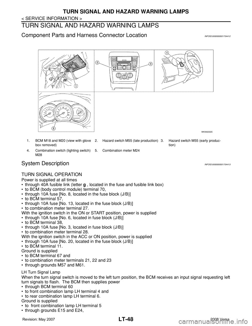
Component Parts and Harness Connector LocationINFOID:0000000001704412
System DescriptionINFOID:0000000001704413
TURN SIGNAL OPERATION
Power is supplied at all times
• through 40A fusible link (letter g , located in the fuse and fusible link box)
• to BCM (body control module) terminal 70,
• through 10A fuse [No. 8, located in the fuse block (J/B)]
• to BCM terminal 57,
• through 10A fuse [No. 13, located in the fuse block (J/B)]
• to combination meter terminal 27.
With the ignition switch in the ON or START position, power is supplied
• through 10A fuse [No. 6, located in fuse block (J/B)]
• to BCM terminal 38,
• through 10A fuse [No. 3, located in fuse block (J/B)]
• to combination meter terminal 28.
With the ignition switch in the ACC or ON position, power is supplied
• through 10A fuse [No. 20, located in the fuse block (J/B)]
• to BCM terminal 11.
Ground is supplied
• to BCM terminal 67 and
• to combination meter terminals 21, 22 and 23
• through grounds M57 and M61.
LH Turn Signal Lamp
When the turn signal switch is moved to the left turn position, the BCM receives an input signal requesting left
turn signals to flash. The BCM then supplies power
• through BCM terminal 60
• to front combination lamp LH terminal 4 and
• to rear combination lamp LH terminal 6.
Ground is supplied
• to front combination lamp LH terminal 5
• through grounds E15 and E24,
1. BCM M18 and M20 (view with glove
box removed)2. Hazard switch M55 (late production) 3. Hazard switch M55 (early produc-
tion)
4. Combination switch (lighting switch)
M285. Combination meter M24
WKIA6002E