2008 NISSAN TIIDA replace battery
[x] Cancel search: replace batteryPage 501 of 2771
REMOTE KEYLESS ENTRY SYSTEM
BL-67
< SERVICE INFORMATION >
C
D
E
F
G
H
J
K
L
MA
B
BL
N
O
P
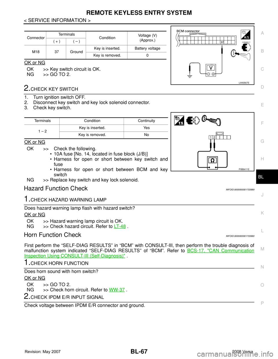
OK or NG
OK >> Key switch circuit is OK.
NG >> GO TO 2.
2.CHECK KEY SWITCH
1. Turn ignition switch OFF.
2. Disconnect key switch and key lock solenoid connector.
3. Check key switch.
OK or NG
OK >> Check the following.
• 10A fuse [No. 14, located in fuse block (J/B)]
• Harness for open or short between key switch and
fuse
• Harness for open or short between BCM and key
switch
NG >> Replace key switch and key lock solenoid.
Hazard Function CheckINFOID:0000000001703989
1.CHECK HAZARD WARNING LAMP
Does hazard warning lamp flash with hazard switch?
OK or NG
OK >> Hazard warning lamp circuit is OK.
NG >> Check hazard circuit. Refer to LT- 4 8
.
Horn Function CheckINFOID:0000000001703990
First perform the “SELF-DIAG RESULTS” in “BCM” with CONSULT-III, then perform the trouble diagnosis of
malfunction system indicated “SELF-DIAG RESULTS” of “BCM”. Refer to BCS-17, "
CAN Communication
Inspection Using CONSULT-III (Self-Diagnosis)" .
1.CHECK HORN FUNCTION
Does horn sound with horn switch?
OK or NG
OK >> GO TO 2.
NG >> Check horn circuit. Refer to WW-37
.
2.CHECK IPDM E/R INPUT SIGNAL
Check voltage between IPDM E/R connector and ground.
ConnectorTe r m i n a l s
ConditionVoltage (V)
(Approx.)
( + ) ( – )
M18 37 GroundKey is inserted. Battery voltage
Key is removed. 0
LIIA0567E
Terminals Condition Continuity
1 – 2Key is inserted. Yes
Key is removed. No
PIIB6411E
Page 502 of 2771
BL-68
< SERVICE INFORMATION >
REMOTE KEYLESS ENTRY SYSTEM
OK or NG
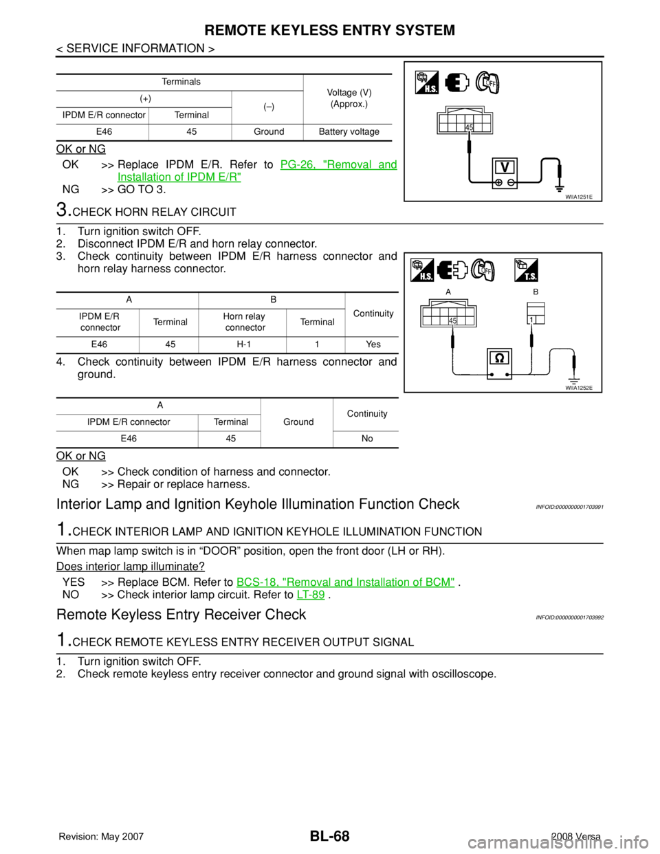
OK >> Replace IPDM E/R. Refer to PG-26, "Removal and
Installation of IPDM E/R"
NG >> GO TO 3.
3.CHECK HORN RELAY CIRCUIT
1. Turn ignition switch OFF.
2. Disconnect IPDM E/R and horn relay connector.
3. Check continuity between IPDM E/R harness connector and
horn relay harness connector.
4. Check continuity between IPDM E/R harness connector and
ground.
OK or NG
OK >> Check condition of harness and connector.
NG >> Repair or replace harness.
Interior Lamp and Ignition Keyhole Illumination Function CheckINFOID:0000000001703991
1.CHECK INTERIOR LAMP AND IGNITION KEYHOLE ILLUMINATION FUNCTION
When map lamp switch is in “DOOR” position, open the front door (LH or RH).
Does interior lamp illuminate?
YES >> Replace BCM. Refer to BCS-18, "Removal and Installation of BCM" .
NO >> Check interior lamp circuit. Refer to LT- 8 9
.
Remote Keyless Entry Receiver CheckINFOID:0000000001703992
1.CHECK REMOTE KEYLESS ENTRY RECEIVER OUTPUT SIGNAL
1. Turn ignition switch OFF.
2. Check remote keyless entry receiver connector and ground signal with oscilloscope.
Te r m i n a l s
Voltage (V)
(Approx.) (+)
(–)
IPDM E/R connector Terminal
E46 45 Ground Battery voltage
WIIA1251E
AB
Continuity
IPDM E/R
connectorTe r m i n a lHorn relay
connectorTe r m i n a l
E46 45 H-1 1 Yes
A
GroundContinuity
IPDM E/R connector Terminal
E46 45 No
WIIA1252E
Page 507 of 2771
REMOTE KEYLESS ENTRY SYSTEM
BL-73
< SERVICE INFORMATION >
C
D
E
F
G
H
J
K
L
MA
B
BL
N
O
P
To erase all ID codes in memory, register one ID code (keyfob) five times. After all ID codes are erased, the
ID codes of all remaining and/or new keyfobs must be re-registered.
• When registering an additional keyfob, the existing ID codes in memory may or may not be erased. If five ID
codes are stored in memory, when an additional code is registered, only the oldest code is erased. If less
than five ID codes are stored in memory, when an additional ID code is registered, the new ID code is added
and no ID codes are erased.
• If you need to activate more than two additional new keyfobs, repeat the procedure “Additional ID code
entry” for each new keyfob.
• Entry of maximum five ID codes is allowed. When more than five ID codes are entered, the oldest ID code
will be erased.
• Even if same ID code that is already in the memory is input, the same ID code can be entered. The code is
counted as an additional code.
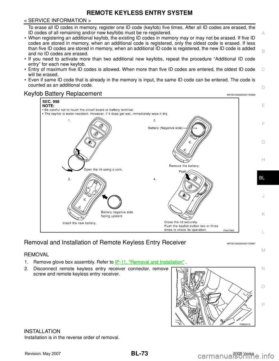
Keyfob Battery ReplacementINFOID:0000000001703996
Removal and Installation of Remote Keyless Entry ReceiverINFOID:0000000001703997
REMOVAL
1. Remove glove box assembly. Refer to IP-11, "Removal and Installation" .
2. Disconnect remote keyless entry receiver connector, remove
screw and remote keyless entry receiver.
INSTALLATION
Installation is in the reverse order of removal.
PIIA4706E
PIIB6541E
Page 533 of 2771
INTELLIGENT KEY SYSTEM
BL-99
< SERVICE INFORMATION >
C
D
E
F
G
H
J
K
L
MA
B
BL
N
O
P
Terminal and Reference Value for BCMINFOID:0000000001704007
Refer to BCS-11, "Terminal and Reference Value for BCM".
Trouble Diagnosis ProcedureINFOID:0000000001704008
PRELIMINARY CHECK
1.GET SYMPTOMS
Listen to customer concerns. (Get symptoms)
NOTE:
If customer reports a “No start” condition, request all Intelligent Keys to be brought to the dealer in case of
Intelligent Key system malfunction.
Intelligent Key or mechanical key service request>>For further information, refer to CONSULT-III operation
manual.
Malfunctions>>GO TO 2.
2.CHECK BCM CONFIGURATION
Confirm BCM configuration for "I-KEY" is set to "WITH". Refer to BCS-17, "
Configuration".
OK or NG
OK >> GO TO 3.
NG >> Change BCM configuration for "I-KEY" to "WITH". Refer to BCS-17, "
Configuration".
3.START ENGINE WITH INTELLIGENT KEY
Check if the engine could be started by all registered Intelligent Keys.
The engine cannot be started by some Intelligent Keys>>Intelligent Key is low battery or malfunction. Refer
to BL-142, "
Intelligent Key Battery Replacement".
The engine cannot be started by all Intelligent Keys>>GO TO 4.
The engine can be started by all Intelligent Keys>>GO TO 5.
4.CHECK “KEY” WARNING LAMP ILLUMINATION
When pushing the ignition switch, check if “KEY” warning lamp in combination meter illuminates.
KEY warning lamp illuminates green>>GO TO BL-103, "
Trouble Diagnosis Symptom Chart".
KEY warning lamp illuminates red>>GO TO BL-103, "
Trouble Diagnosis Symptom Chart".
Does not illuminate>>GO TO BL-103, "
Trouble Diagnosis Symptom Chart".
5.START ENGINE WITH MECHANICAL KEY
Check if the engine could be started by all registered mechanical keys.
No start by some mechanical keys>>Register mechanical key. Refer to CONSULT-III operation manual.
Engine starts by mechanical or Intelligent Key>>GO TO BL-103, "
Trouble Diagnosis Symptom Chart".
No start by mechanical key or Intelligent Key>>GO TO NATS BL-215, "
Trouble Diagnosis Procedure".
Engine starts with Intelligent Key or mechanical key>>GO TO "WORK FLOW".
The engine can be started by all mechanical keys>>GO TO 6.
6.PERFORM SELF-DIAGNOSIS
1. Turn ignition switch to ON by carrying the Intelligent Key.
2. Perform self-diagnosis of Intelligent Key system with CONSULT-III.
DTC is displayed>>GO TO BL-101, "
CONSULT-III Application Item".
DTC is not displayed>>GO TO BL-103, "
Trouble Diagnosis Symptom Chart".
WORK FLOW
Before performing the work flow, carry out preliminary check. Refer to "PRELIMINARY CHECK".
Page 539 of 2771
INTELLIGENT KEY SYSTEM
BL-105
< SERVICE INFORMATION >
C
D
E
F
G
H
J
K
L
MA
B
BL
N
O
P
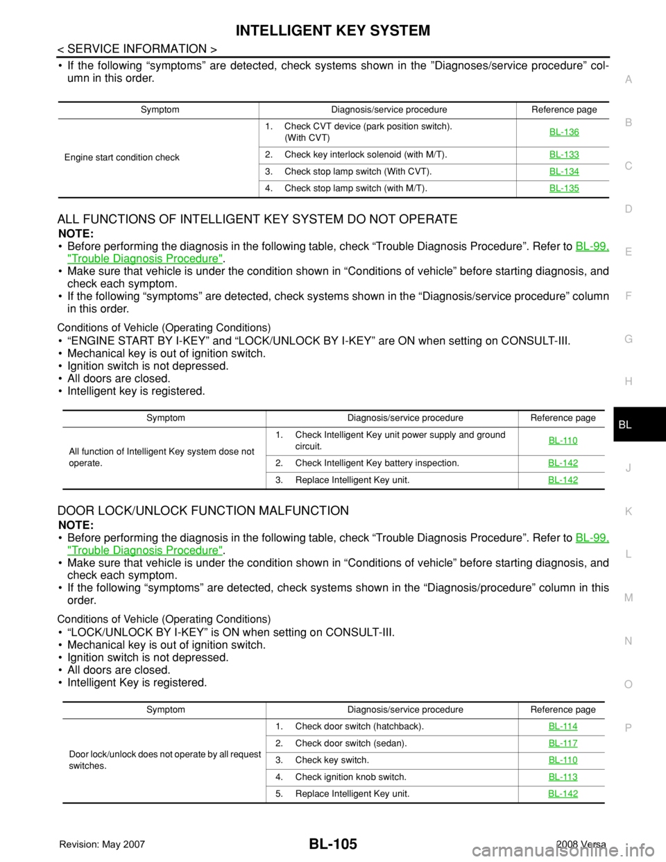
• If the following “symptoms” are detected, check systems shown in the ”Diagnoses/service procedure” col-
umn in this order.
ALL FUNCTIONS OF INTELLIGENT KEY SYSTEM DO NOT OPERATE
NOTE:
• Before performing the diagnosis in the following table, check “Trouble Diagnosis Procedure”. Refer to BL-99,
"Trouble Diagnosis Procedure".
• Make sure that vehicle is under the condition shown in “Conditions of vehicle” before starting diagnosis, and
check each symptom.
• If the following “symptoms” are detected, check systems shown in the “Diagnosis/service procedure” column
in this order.
Conditions of Vehicle (Operating Conditions)
• “ENGINE START BY I-KEY” and “LOCK/UNLOCK BY I-KEY” are ON when setting on CONSULT-III.
• Mechanical key is out of ignition switch.
• Ignition switch is not depressed.
• All doors are closed.
• Intelligent key is registered.
DOOR LOCK/UNLOCK FUNCTION MALFUNCTION
NOTE:
• Before performing the diagnosis in the following table, check “Trouble Diagnosis Procedure”. Refer to BL-99,
"Trouble Diagnosis Procedure".
• Make sure that vehicle is under the condition shown in “Conditions of vehicle” before starting diagnosis, and
check each symptom.
• If the following “symptoms” are detected, check systems shown in the “Diagnosis/procedure” column in this
order.
Conditions of Vehicle (Operating Conditions)
• “LOCK/UNLOCK BY I-KEY” is ON when setting on CONSULT-III.
• Mechanical key is out of ignition switch.
• Ignition switch is not depressed.
• All doors are closed.
• Intelligent Key is registered.
Symptom Diagnosis/service procedure Reference page
Engine start condition check1. Check CVT device (park position switch).
(With CVT)BL-136
2. Check key interlock solenoid (with M/T).BL-133
3. Check stop lamp switch (With CVT).BL-134
4. Check stop lamp switch (with M/T).BL-135
Symptom Diagnosis/service procedure Reference page
All function of Intelligent Key system dose not
operate.1. Check Intelligent Key unit power supply and ground
circuit.BL-110
2. Check Intelligent Key battery inspection.BL-142
3. Replace Intelligent Key unit.BL-142
Symptom Diagnosis/service procedure Reference page
Door lock/unlock does not operate by all request
switches.1. Check door switch (hatchback).BL-114
2. Check door switch (sedan).BL-117
3. Check key switch.BL-110
4. Check ignition knob switch.BL-113
5. Replace Intelligent Key unit.BL-142
Page 540 of 2771

BL-106
< SERVICE INFORMATION >
INTELLIGENT KEY SYSTEM
REMOTE KEYLESS ENTRY FUNCTION MALFUNCTION
NOTE:
• Before performing the diagnosis in the following table, check “Trouble Diagnosis Procedure”. Refer to BL-99,
"Trouble Diagnosis Procedure".
• Make sure that vehicle is under the condition shown in “Conditions of vehicle” before starting diagnosis, and
check each symptom.
• If the following “symptoms” are detected, check systems shown in the “Diagnosis/service procedure” column
in this order.
Conditions of Vehicle (Operating Conditions)
• Ignition switch is not depressed.
• All doors are closed.
Door lock/unlock does not operate by request
switch (driver side).1. Check door request switch (driver side).BL-1182. Check outside key antenna (driver side).BL-126
3. Replace Intelligent Key unit.BL-142
Door lock/unlock does not operate by request
switch (passenger side).1. Check door request switch (passenger side).BL-1182. Check outside key antenna (passenger side).BL-126
3. Replace Intelligent Key unit.BL-142
Door lock/unlock does not operate by back door
request switch (hatchback).1. Check back door request switch.BL-1202. Check outside key antenna (rear bumper).BL-128
3. Replace Intelligent Key unit.BL-142
Door lock/unlock does not operate by trunk
opener request switch (sedan).1. Check trunk opener request switch.BL-1222. Check outside key antenna (rear bumper).BL-128
3. Replace Intelligent Key unit.BL-142
Auto lock function does not operate.1. Check “AUTO RELOCK TIMER” setting in “WORK
SUPPORT”.BL-101
2. Replace Intelligent Key unit.BL-142
Key reminder function does not operate.1. Check door switch (hatchback).BL-114
2. Check door switch (sedan).BL-117
3. Check inside key antenna.BL-129
4. Check unlock sensor.BL-124
5. Check Intelligent Key battery.BL-142
6. Replace Intelligent Key unit.BL-142
Symptom Diagnosis/service procedure Reference page
Symptom Diagnosis/service procedureReference
page
All of the remote keyless entry functions do
not operate.1. Check Intelligent Key unit power supply and ground circuit.BL-110
2. Check key switch (BCM input).BL-112
3. Check Intelligent Key battery.BL-142
4. Remote Keyless Entry function inspection.BL-142
5. Replace Intelligent Key unit.BL-142
Auto lock function does not operate.1. Check “AUTO RELOCK TIMER” setting in “WORK SUPPORT”.BL-1012. Replace Intelligent Key unit.BL-142
Page 541 of 2771
INTELLIGENT KEY SYSTEM
BL-107
< SERVICE INFORMATION >
C
D
E
F
G
H
J
K
L
MA
B
BL
N
O
P
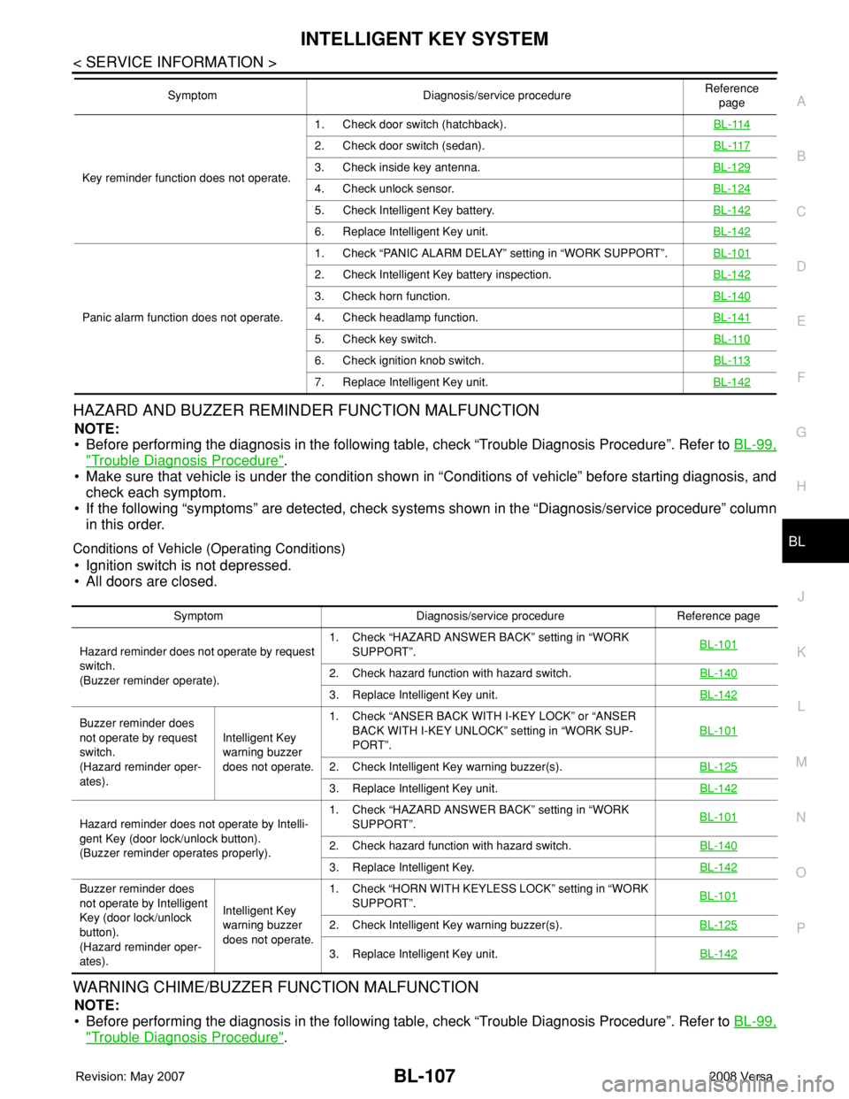
HAZARD AND BUZZER REMINDER FUNCTION MALFUNCTION
NOTE:
• Before performing the diagnosis in the following table, check “Trouble Diagnosis Procedure”. Refer to BL-99,
"Trouble Diagnosis Procedure".
• Make sure that vehicle is under the condition shown in “Conditions of vehicle” before starting diagnosis, and
check each symptom.
• If the following “symptoms” are detected, check systems shown in the “Diagnosis/service procedure” column
in this order.
Conditions of Vehicle (Operating Conditions)
• Ignition switch is not depressed.
• All doors are closed.
WARNING CHIME/BUZZER FUNCTION MALFUNCTION
NOTE:
• Before performing the diagnosis in the following table, check “Trouble Diagnosis Procedure”. Refer to BL-99,
"Trouble Diagnosis Procedure".
Key reminder function does not operate.1. Check door switch (hatchback).BL-114
2. Check door switch (sedan).BL-117
3. Check inside key antenna.BL-129
4. Check unlock sensor.BL-124
5. Check Intelligent Key battery.BL-142
6. Replace Intelligent Key unit.BL-142
Panic alarm function does not operate.1. Check “PANIC ALARM DELAY” setting in “WORK SUPPORT”.BL-101
2. Check Intelligent Key battery inspection.BL-142
3. Check horn function.BL-140
4. Check headlamp function.BL-141
5. Check key switch.BL-110
6. Check ignition knob switch.BL-113
7. Replace Intelligent Key unit.BL-142
Symptom Diagnosis/service procedureReference
page
Symptom Diagnosis/service procedure Reference page
Hazard reminder does not operate by request
switch.
(Buzzer reminder operate).1. Check “HAZARD ANSWER BACK” setting in “WORK
SUPPORT”.BL-101
2. Check hazard function with hazard switch.BL-140
3. Replace Intelligent Key unit.BL-142
Buzzer reminder does
not operate by request
switch.
(Hazard reminder oper-
ates).Intelligent Key
warning buzzer
does not operate.1. Check “ANSER BACK WITH I-KEY LOCK” or “ANSER
BACK WITH I-KEY UNLOCK” setting in “WORK SUP-
PORT”.BL-101
2. Check Intelligent Key warning buzzer(s).BL-125
3. Replace Intelligent Key unit.BL-142
Hazard reminder does not operate by Intelli-
gent Key (door lock/unlock button).
(Buzzer reminder operates properly).1. Check “HAZARD ANSWER BACK” setting in “WORK
SUPPORT”.BL-101
2. Check hazard function with hazard switch.BL-140
3. Replace Intelligent Key.BL-142
Buzzer reminder does
not operate by Intelligent
Key (door lock/unlock
button).
(Hazard reminder oper-
ates).Intelligent Key
warning buzzer
does not operate.1. Check “HORN WITH KEYLESS LOCK” setting in “WORK
SUPPORT”.BL-101
2. Check Intelligent Key warning buzzer(s).BL-125
3. Replace Intelligent Key unit.BL-142
Page 543 of 2771
INTELLIGENT KEY SYSTEM
BL-109
< SERVICE INFORMATION >
C
D
E
F
G
H
J
K
L
MA
B
BL
N
O
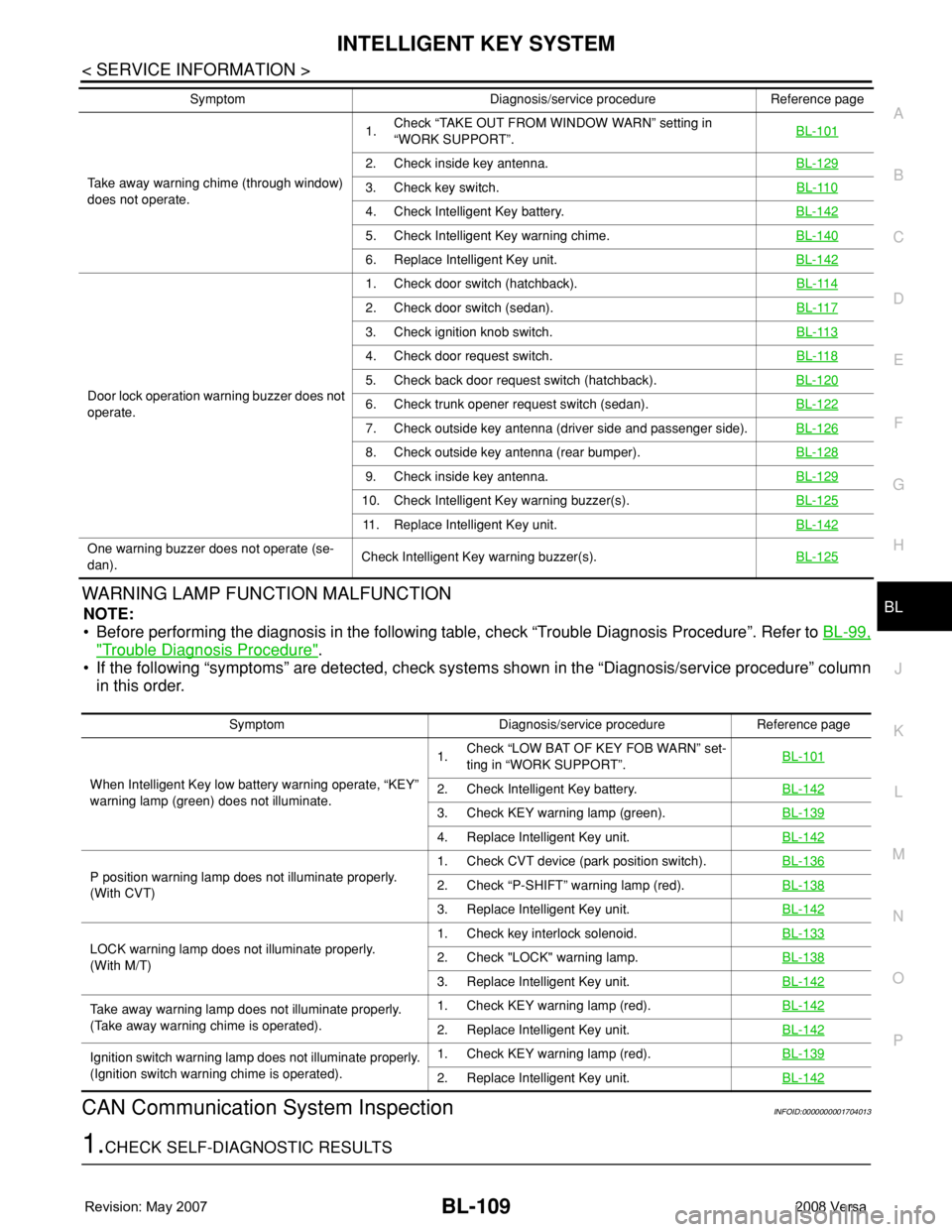
PWARNING LAMP FUNCTION MALFUNCTION
NOTE:
• Before performing the diagnosis in the following table, check “Trouble Diagnosis Procedure”. Refer to BL-99,
"Trouble Diagnosis Procedure".
• If the following “symptoms” are detected, check systems shown in the “Diagnosis/service procedure” column
in this order.
CAN Communication System InspectionINFOID:0000000001704013
1.CHECK SELF-DIAGNOSTIC RESULTS
Take away warning chime (through window)
does not operate.1.Check “TAKE OUT FROM WINDOW WARN” setting in
“WORK SUPPORT”.BL-101
2. Check inside key antenna.BL-129
3. Check key switch.BL-110
4. Check Intelligent Key battery.BL-142
5. Check Intelligent Key warning chime.BL-140
6. Replace Intelligent Key unit.BL-142
Door lock operation warning buzzer does not
operate.1. Check door switch (hatchback).BL-114
2. Check door switch (sedan).BL-117
3. Check ignition knob switch.BL-113
4. Check door request switch.BL-118
5. Check back door request switch (hatchback).BL-120
6. Check trunk opener request switch (sedan).BL-122
7. Check outside key antenna (driver side and passenger side).BL-126
8. Check outside key antenna (rear bumper).BL-128
9. Check inside key antenna.BL-129
10. Check Intelligent Key warning buzzer(s).BL-125
11. Replace Intelligent Key unit.BL-142
One warning buzzer does not operate (se-
dan).Check Intelligent Key warning buzzer(s).BL-125
Symptom Diagnosis/service procedure Reference page
Symptom Diagnosis/service procedure Reference page
When Intelligent Key low battery warning operate, “KEY”
warning lamp (green) does not illuminate.1.Check “LOW BAT OF KEY FOB WARN” set-
ting in “WORK SUPPORT”.BL-101
2. Check Intelligent Key battery.BL-142
3. Check KEY warning lamp (green).BL-139
4. Replace Intelligent Key unit.BL-142
P position warning lamp does not illuminate properly.
(With CVT)1. Check CVT device (park position switch).BL-1362. Check “P-SHIFT” warning lamp (red).BL-138
3. Replace Intelligent Key unit.BL-142
LOCK warning lamp does not illuminate properly.
(With M/T)1. Check key interlock solenoid.BL-1332. Check "LOCK" warning lamp.BL-138
3. Replace Intelligent Key unit.BL-142
Take away warning lamp does not illuminate properly.
(Take away warning chime is operated).1. Check KEY warning lamp (red).BL-142
2. Replace Intelligent Key unit.BL-142
Ignition switch warning lamp does not illuminate properly.
(Ignition switch warning chime is operated).1. Check KEY warning lamp (red).BL-139
2. Replace Intelligent Key unit.BL-142