Page 2545 of 2771
TROUBLE DIAGNOSIS
RF-15
< FUNCTION DIAGNOSIS >
C
D
E
F
G
H
J
K
L
MA
B
RF
N
O
P
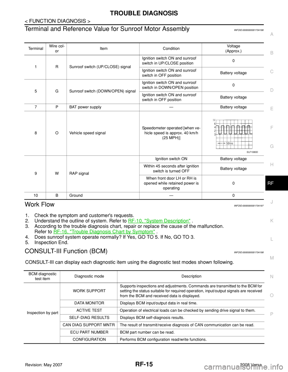
Terminal and Reference Value for Sunroof Motor AssemblyINFOID:0000000001704196
Work FlowINFOID:0000000001704197
1. Check the symptom and customer's requests.
2. Understand the outline of system. Refer to RF-10, "
System Description" .
3. According to the trouble diagnosis chart, repair or replace the cause of the malfunction.
Refer to RF-16, "
Trouble Diagnosis Chart by Symptom" .
4. Does sunroof system operate normally? If Yes, GO TO 5. If No, GO TO 3.
5. Inspection End.
CONSULT-III Function (BCM)INFOID:0000000001704198
CONSULT-III can display each diagnostic item using the diagnostic test modes shown following.
Te r m i n a lWire col-
orItem ConditionVoltag e
(Approx.)
1 R Sunroof switch (UP/CLOSE) signalIgnition switch ON and sunroof
switch in UP/CLOSE position0
Ignition switch ON and sunroof
switch in OFF positionBattery voltage
5 G Sunroof switch (DOWN/OPEN) signalIgnition switch ON and sunroof
switch in DOWN/OPEN position0
Ignition switch ON and sunroof
switch in OFF positionBattery voltage
7PBAT power supply — Battery voltage
8 O Vehicle speed signalSpeedometer operated [when ve-
hicle speed is approx. 40 km/h
(25 MPH)]
9 W RAP signalIgnition switch ON Battery voltage
Within 45 seconds after ignition
switch is turned OFFBattery voltage
When front door LH or RH is
opened while retained power is
operating0
10 B Ground — 0
ELF1080D
BCM diagnostic
test itemDiagnostic mode Description
Inspection by partWORK SUPPORTSupports inspections and adjustments. Commands are transmitted to the BCM for
setting the status suitable for required operation, input/output signals are received
from the BCM and received data is displayed.
DATA MONITOR Displays BCM input/output data in real time.
ACTIVE TEST Operation of electrical loads can be checked by sending drive signal to them.
SELF-DIAG RESULTS Displays BCM self-diagnosis results.
CAN DIAG SUPPORT MNTR The result of transmit/receive diagnosis of CAN communication can be read.
ECU PART NUMBER BCM part number can be read.
CONFIGURATION Performs BCM configuration read/write functions.
Page 2547 of 2771
TROUBLE DIAGNOSIS
RF-17
< FUNCTION DIAGNOSIS >
C
D
E
F
G
H
J
K
L
MA
B
RF
N
O
P
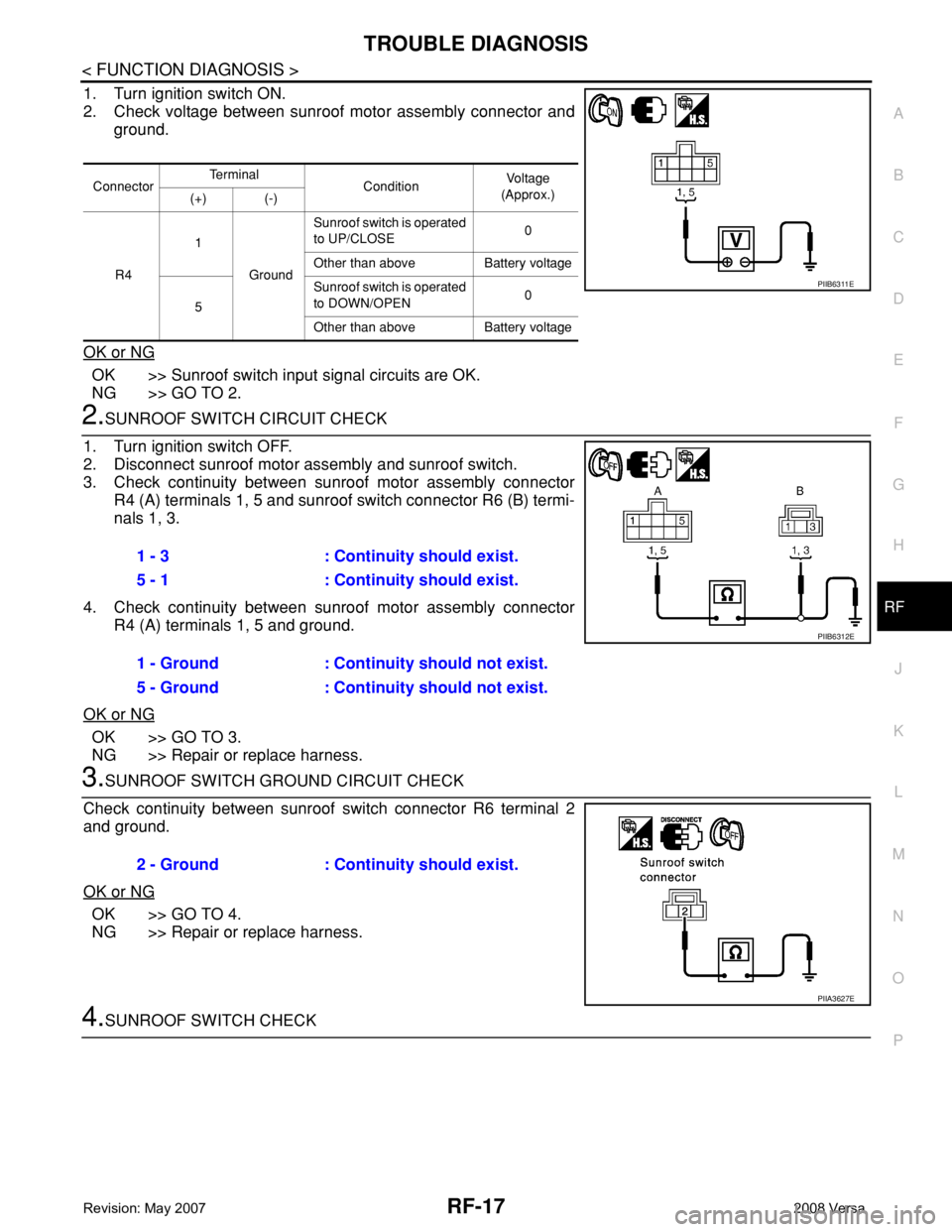
1. Turn ignition switch ON.
2. Check voltage between sunroof motor assembly connector and
ground.
OK or NG
OK >> Sunroof switch input signal circuits are OK.
NG >> GO TO 2.
2.SUNROOF SWITCH CIRCUIT CHECK
1. Turn ignition switch OFF.
2. Disconnect sunroof motor assembly and sunroof switch.
3. Check continuity between sunroof motor assembly connector
R4 (A) terminals 1, 5 and sunroof switch connector R6 (B) termi-
nals 1, 3.
4. Check continuity between sunroof motor assembly connector
R4 (A) terminals 1, 5 and ground.
OK or NG
OK >> GO TO 3.
NG >> Repair or replace harness.
3.SUNROOF SWITCH GROUND CIRCUIT CHECK
Check continuity between sunroof switch connector R6 terminal 2
and ground.
OK or NG
OK >> GO TO 4.
NG >> Repair or replace harness.
4.SUNROOF SWITCH CHECK
ConnectorTe r m i n a l
ConditionVo l ta g e
(Approx.)
(+) (-)
R41
GroundSunroof switch is operated
to UP/CLOSE0
Other than above Battery voltage
5Sunroof switch is operated
to DOWN/OPEN0
Other than above Battery voltage
PIIB6311E
1 - 3 : Continuity should exist.
5 - 1 : Continuity should exist.
1 - Ground : Continuity should not exist.
5 - Ground : Continuity should not exist.
PIIB6312E
2 - Ground : Continuity should exist.
PIIA3627E
Page 2548 of 2771
RF-18
< FUNCTION DIAGNOSIS >
TROUBLE DIAGNOSIS
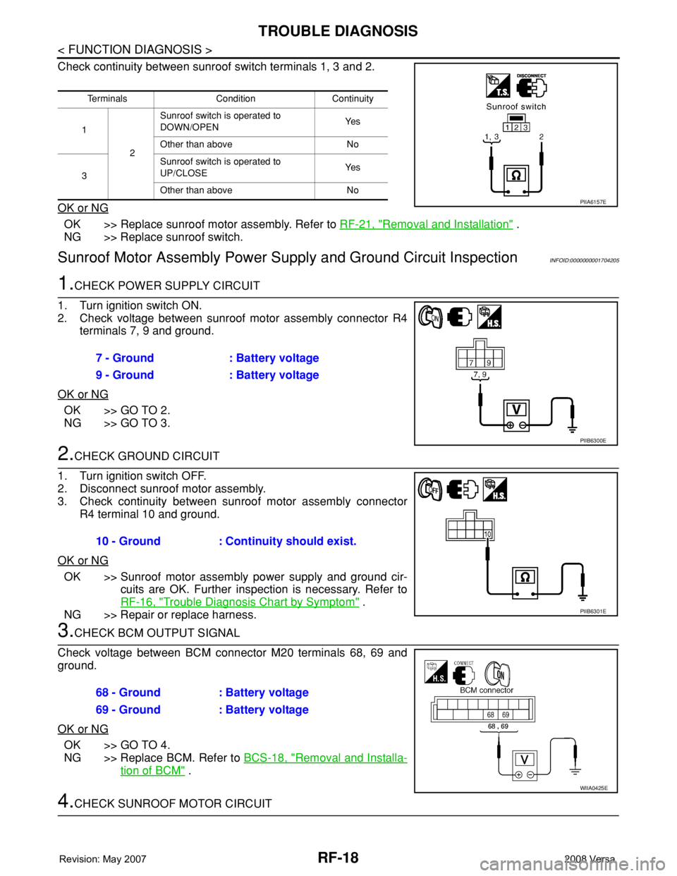
Check continuity between sunroof switch terminals 1, 3 and 2.
OK or NG
OK >> Replace sunroof motor assembly. Refer to RF-21, "Removal and Installation" .
NG >> Replace sunroof switch.
Sunroof Motor Assembly Power Supply and Ground Circuit InspectionINFOID:0000000001704205
1.CHECK POWER SUPPLY CIRCUIT
1. Turn ignition switch ON.
2. Check voltage between sunroof motor assembly connector R4
terminals 7, 9 and ground.
OK or NG
OK >> GO TO 2.
NG >> GO TO 3.
2.CHECK GROUND CIRCUIT
1. Turn ignition switch OFF.
2. Disconnect sunroof motor assembly.
3. Check continuity between sunroof motor assembly connector
R4 terminal 10 and ground.
OK or NG
OK >> Sunroof motor assembly power supply and ground cir-
cuits are OK. Further inspection is necessary. Refer to
RF-16, "
Trouble Diagnosis Chart by Symptom" .
NG >> Repair or replace harness.
3.CHECK BCM OUTPUT SIGNAL
Check voltage between BCM connector M20 terminals 68, 69 and
ground.
OK or NG
OK >> GO TO 4.
NG >> Replace BCM. Refer to BCS-18, "
Removal and Installa-
tion of BCM" .
4.CHECK SUNROOF MOTOR CIRCUIT
Terminals Condition Continuity
1
2Sunroof switch is operated to
DOWN/OPENYe s
Other than above No
3Sunroof switch is operated to
UP/CLOSEYe s
Other than above No
PIIA6157E
7 - Ground : Battery voltage
9 - Ground : Battery voltage
PIIB6300E
10 - Ground : Continuity should exist.
PIIB6301E
68 - Ground : Battery voltage
69 - Ground : Battery voltage
WIIA0425E
Page 2549 of 2771
TROUBLE DIAGNOSIS
RF-19
< FUNCTION DIAGNOSIS >
C
D
E
F
G
H
J
K
L
MA
B
RF
N
O
P
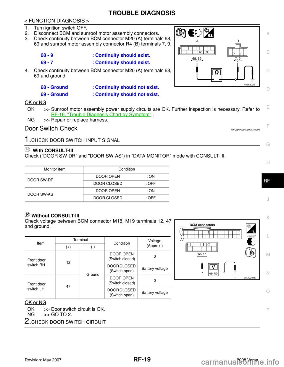
1. Turn ignition switch OFF.
2. Disconnect BCM and sunroof motor assembly connectors.
3. Check continuity between BCM connector M20 (A) terminals 68,
69 and sunroof motor assembly connector R4 (B) terminals 7, 9.
4. Check continuity between BCM connector M20 (A) terminals 68,
69 and ground.
OK or NG
OK >> Sunroof motor assembly power supply circuits are OK. Further inspection is necessary. Refer to
RF-16, "
Trouble Diagnosis Chart by Symptom" .
NG >> Repair or replace harness.
Door Switch CheckINFOID:0000000001704206
1.CHECK DOOR SWITCH INPUT SIGNAL
With CONSULT-III
Check ("DOOR SW-DR" and "DOOR SW-AS") in "DATA MONITOR" mode with CONSULT-III.
Without CONSULT-III
Check voltage between BCM connector M18, M19 terminals 12, 47
and ground.
OK or NG
OK >> Door switch circuit is OK.
NG >> GO TO 2.
2.CHECK DOOR SWITCH CIRCUIT68 - 9 : Continuity should exist.
69 - 7 : Continuity should exist.
68 - Ground : Continuity should not exist.
69 - Ground : Continuity should not exist.
PIIB6302E
Monitor item Condition
DOOR SW-DRDOOR OPEN : ON
DOOR CLOSED : OFF
DOOR SW-ASDOOR OPEN : ON
DOOR CLOSED : OFF
ItemTe r m i n a l
ConditionVoltag e
(Approx.)
(+) (-)
Front door
switch RH12
GroundDOOR OPEN
(Switch closed)0
DOOR CLOSED
(Switch open)Battery voltage
Front door
switch LH47DOOR OPEN
(Switch closed)0
DOOR CLOSED
(Switch open)Battery voltage
WIIA0234E
Page 2550 of 2771
RF-20
< FUNCTION DIAGNOSIS >
TROUBLE DIAGNOSIS
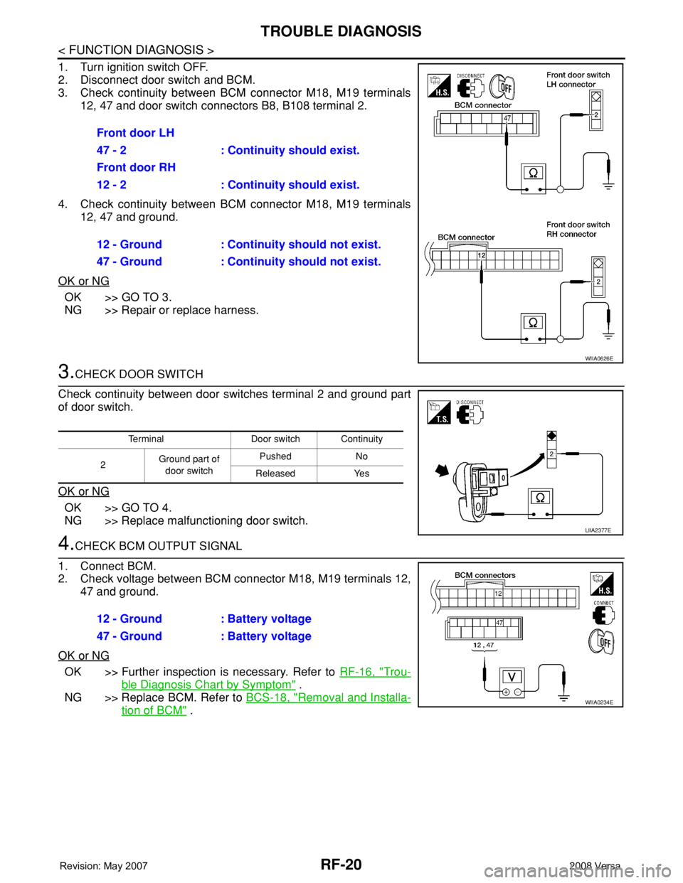
1. Turn ignition switch OFF.
2. Disconnect door switch and BCM.
3. Check continuity between BCM connector M18, M19 terminals
12, 47 and door switch connectors B8, B108 terminal 2.
4. Check continuity between BCM connector M18, M19 terminals
12, 47 and ground.
OK or NG
OK >> GO TO 3.
NG >> Repair or replace harness.
3.CHECK DOOR SWITCH
Check continuity between door switches terminal 2 and ground part
of door switch.
OK or NG
OK >> GO TO 4.
NG >> Replace malfunctioning door switch.
4.CHECK BCM OUTPUT SIGNAL
1. Connect BCM.
2. Check voltage between BCM connector M18, M19 terminals 12,
47 and ground.
OK or NG
OK >> Further inspection is necessary. Refer to RF-16, "Trou-
ble Diagnosis Chart by Symptom" .
NG >> Replace BCM. Refer to BCS-18, "
Removal and Installa-
tion of BCM" . Front door LH
47 - 2 : Continuity should exist.
Front door RH
12 - 2 : Continuity should exist.
12 - Ground : Continuity should not exist.
47 - Ground : Continuity should not exist.
WIIA0626E
Terminal Door switch Continuity
2Ground part of
door switchPushed No
Released Yes
LIIA2377E
12 - Ground : Battery voltage
47 - Ground : Battery voltage
WIIA0234E
Page 2586 of 2771
SC-4
< SERVICE INFORMATION >
BATTERY
BATTERY
How to Handle BatteryINFOID:0000000001704345
CAUTION:
• If it becomes necessary to start the engine with a booster battery and jumper cables, use a 12-volt
booster battery.
• After connecting battery cables, ensure that they are tightly clamped to battery terminals for good
contact.
• Never add distilled water through the hole used to check specific gravity.
METHODS OF PREVENTING OVER-DISCHARGE
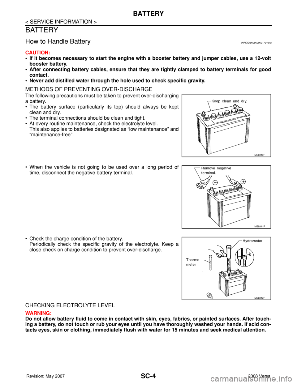
The following precautions must be taken to prevent over-discharging
a battery.
• The battery surface (particularly its top) should always be kept
clean and dry.
• The terminal connections should be clean and tight.
• At every routine maintenance, check the electrolyte level.
This also applies to batteries designated as “low maintenance” and
“maintenance-free”.
• When the vehicle is not going to be used over a long period of
time, disconnect the negative battery terminal.
• Check the charge condition of the battery.
Periodically check the specific gravity of the electrolyte. Keep a
close check on charge condition to prevent over-discharge.
CHECKING ELECTROLYTE LEVEL
WARNING:
Do not allow battery fluid to come in contact with skin, eyes, fabrics, or painted surfaces. After touch-
ing a battery, do not touch or rub your eyes until you have thoroughly washed your hands. If acid con-
tacts eyes, skin or clothing, immediately flush with water for 15 minutes and seek medical attention.
MEL040F
MEL041F
MEL042F
Page 2588 of 2771
SC-6
< SERVICE INFORMATION >
BATTERY
CHARGING THE BATTERY
CAUTION:
• Do not “quick charge” a fully discharged battery.
• Keep the battery away from open flame while it is being charged.
• When connecting the charger, connect the leads first, then turn on the charger. Do not turn on the
charger first, as this may cause a spark.
• If battery electrolyte temperature rises above 55°C (131°F), stop charging. Always charge battery at a
temperature below 55°C (131°F).
Charging Rates
Do not charge at more than 50 ampere rate.
NOTE:
The ammeter reading on your battery charger will automatically decrease as the battery charges. This indi-
cates that the voltage of the battery is increasing normally as the state of charge improves. The charging amps
indicated above refer to initial charge rate.
• If, after charging, the specific gravity of any two cells varies more than 0.050, the battery should be replaced.
Trouble Diagnosis with Battery Service CenterINFOID:0000000001704346
For battery testing, use Battery Service Center (J-48087). For details and operating instructions, refer to Tech-
nical Service Bulletin and/or Battery Service Center User Guide.
Removal and InstallationINFOID:0000000001704347
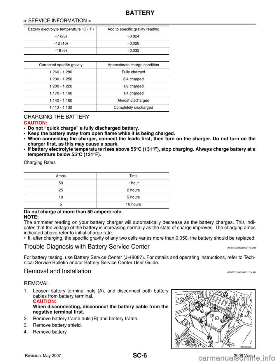
REMOVAL
1. Loosen battery terminal nuts (A), and disconnect both battery
cables from battery terminal.
CAUTION:
When disconnecting, disconnect the battery cable from the
negative terminal first.
2. Remove battery frame nuts (B) and battery frame.
3. Remove battery shield.
4. Remove battery.
−7 (20)−0.024
−12 (10)−0.028
−18 (0)−0.032
Corrected specific gravity Approximate charge condition
1.260 - 1.280 Fully charged
1.230 - 1.250 3/4 charged
1.200 - 1.220 1/2 charged
1.170 - 1.190 1/4 charged
1.140 - 1.160 Almost discharged
1.110 - 1.130 Completely discharged Battery electrolyte temperature °C (°F) Add to specific gravity reading
Amps Time
50 1 hour
25 2 hours
10 5 hours
5 10 hours
PKIC0535E
Page 2589 of 2771
BATTERY
SC-7
< SERVICE INFORMATION >
C
D
E
F
G
H
I
J
L
MA
B
SC
N
O
P
INSTALLATION
Installation is in the reverse order of removal.
CAUTION:
When connecting, connect the battery cable to the positive terminal first.
Battery frame nut : 3.9 N·m (0.40 kg-m, 35 in-lb)
Battery terminal nut : 5.4 N·m (0.55 kg-m, 48 in-lb)