2008 NISSAN TIIDA Fluid
[x] Cancel search: FluidPage 77 of 2771
TROUBLE DIAGNOSIS
AT-65
< SERVICE INFORMATION >
D
E
F
G
H
I
J
K
L
MA
B
AT
N
O
P
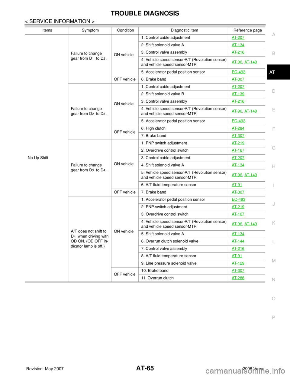
No Up ShiftFailure to change
gear from D
1 to D2 .ON vehicle1. Control cable adjustmentAT- 2 0 7
2. Shift solenoid valve AAT- 1 3 4
3. Control valve assemblyAT- 2 1 6
4. Vehicle speed sensor·A/T (Revolution sensor)
and vehicle speed sensor·MTRAT- 9 6, AT- 1 4 9
5. Accelerator pedal position sensorEC-493
OFF vehicle 6. Brake bandAT- 3 0 7
Failure to change
gear from D
2 to D3 .ON vehicle1. Control cable adjustmentAT- 2 0 7
2. Shift solenoid valve BAT- 1 3 9
3. Control valve assemblyAT- 2 1 6
4. Vehicle speed sensor·A/T (Revolution sensor)
and vehicle speed sensor·MTRAT- 9 6, AT- 1 4 9
5. Accelerator pedal position sensorEC-493
OFF vehicle6. High clutchAT- 2 8 47. Brake bandAT- 3 0 7
Failure to change
gear from D
3 to D4 .ON vehicle 1. PNP switch adjustmentAT- 2 1 9
2. Overdrive control switchAT- 1 6 7
3. Control cable adjustmentAT- 2 0 7
4. Shift solenoid valve AAT- 1 3 4
5. Vehicle speed sensor·A/T (Revolution sensor)
and vehicle speed sensor·MTRAT- 9 6, AT- 1 4 9
6. A/T fluid temperature sensorAT- 9 1
OFF vehicle 7. Brake band AT- 3 0 7
A/T does not shift to
D
4 when driving with
OD ON. (OD OFF in-
dicator lamp is off.)ON vehicle1. Accelerator pedal position sensorEC-493
2. PNP switch adjustmentAT- 2 1 9
3. Overdrive control switchAT- 1 6 7
4. Vehicle speed sensor·A/T (Revolution sensor)
and vehicle speed sensor·MTRAT- 9 6, AT- 1 4 9
5. Shift solenoid valve AAT- 1 3 4
6. Overrun clutch solenoid valveAT- 1 4 4
7. Control valve assemblyAT- 2 1 6
8. A/T fluid temperature sensorAT- 9 1
9. Line pressure solenoid valveAT- 1 2 9
OFF vehicle10. Brake bandAT- 3 0 711. Overrun clutchAT- 2 8 8
Items Symptom Condition Diagnostic item Reference page
Page 78 of 2771

AT-66
< SERVICE INFORMATION >
TROUBLE DIAGNOSIS
Slips/Will Not EngageVehicle will not run in
“R” position (but runs
in “D”, “2” and “1” po-
sitions). Clutch slips.
Very poor accelera-
tion.ON vehicle1. Control cable adjustmentAT- 2 0 7
2. Stall testAT- 4 8
3. Line pressure testAT- 4 8
4. Line pressure solenoid valveAT- 1 2 9
5. Control valve assemblyAT- 2 1 6
OFF vehicle6. Reverse clutchAT- 2 7 9
7. High clutchAT- 2 8 4
8. Forward clutchAT- 2 8 8
9. Overrun clutchAT- 2 8 8
10. Low & reverse brakeAT- 2 9 5
Vehicle will not run in
“D” and “2” positions
(but runs in “1” and
“R” positions).ON vehicle 1. Control cable adjustmentAT- 2 0 7
OFF vehicle 2. Low one-way clutchAT- 2 4 0
Vehicle will not run in
“D”, “1”, “2” positions
(but runs in R posi-
tion). Clutch slips.
Very poor accelera-
tion.ON vehicle1. A/T fluid levelMA-22
2. Stall testAT- 4 8
3. Line pressure testAT- 4 8
4. Line pressure solenoid valveAT- 1 2 9
5. Control valve assemblyAT- 2 1 6
6. Accumulator N-DAT- 2 1 6
OFF vehicle7. Reverse clutchAT- 2 7 9
8. High clutchAT- 2 8 4
9. Forward clutchAT- 2 8 8
10. Forward one-way clutchAT- 2 9 9
11. Low one-way clutchAT- 2 4 0
Clutches or brakes
slip somewhat in start-
ing.ON vehicle1. A/T fluid levelMA-22
2. Control cable adjustmentAT- 2 0 7
3. Accelerator pedal position sensorEC-493
4. Line pressure testAT- 4 8
5. Line pressure solenoid valveAT- 1 2 9
6. Control valve assemblyAT- 2 1 6
7. Accumulator N-DAT- 2 1 6
OFF vehicle8. Forward clutchAT- 2 8 8
9. Reverse clutchAT- 2 7 9
10. Low & reverse brakeAT- 2 9 5
11 . O i l p u m pAT- 2 6 0
12. Torque converterAT- 2 4 0
Items Symptom Condition Diagnostic item Reference page
Page 79 of 2771
TROUBLE DIAGNOSIS
AT-67
< SERVICE INFORMATION >
D
E
F
G
H
I
J
K
L
MA
B
AT
N
O
P
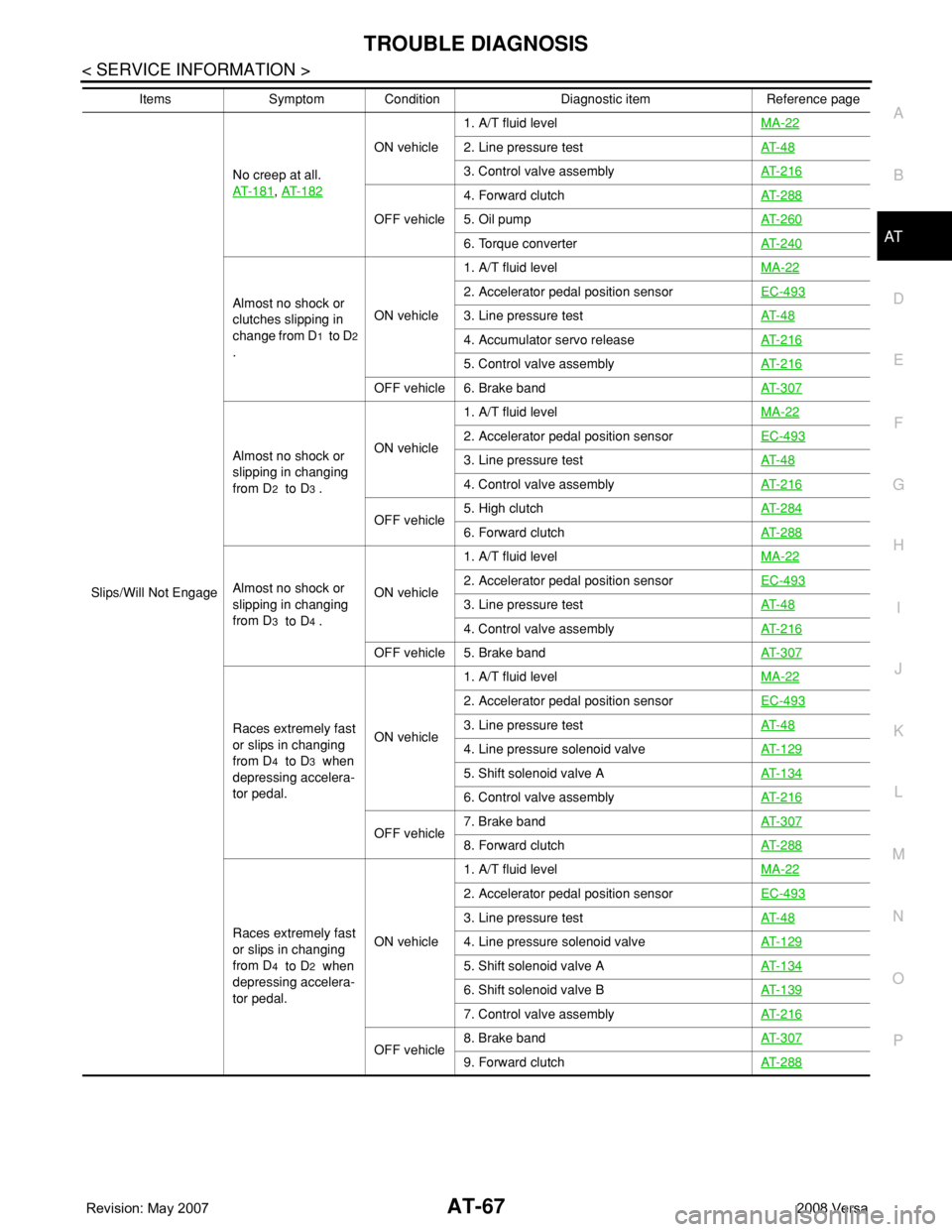
Slips/Will Not EngageNo creep at all.
AT- 1 8 1
, AT- 1 8 2
ON vehicle1. A/T fluid levelMA-222. Line pressure testAT- 4 8
3. Control valve assemblyAT- 2 1 6
OFF vehicle4. Forward clutchAT- 2 8 85. Oil pumpAT- 2 6 0
6. Torque converterAT- 2 4 0
Almost no shock or
clutches slipping in
change from D
1 to D2
.ON vehicle1. A/T fluid levelMA-22
2. Accelerator pedal position sensorEC-493
3. Line pressure testAT- 4 8
4. Accumulator servo releaseAT- 2 1 6
5. Control valve assemblyAT- 2 1 6
OFF vehicle 6. Brake bandAT- 3 0 7
Almost no shock or
slipping in changing
from D
2 to D3 .ON vehicle1. A/T fluid levelMA-22
2. Accelerator pedal position sensorEC-493
3. Line pressure testAT- 4 8
4. Control valve assemblyAT- 2 1 6
OFF vehicle5. High clutchAT- 2 8 46. Forward clutchAT- 2 8 8
Almost no shock or
slipping in changing
from D
3 to D4 .ON vehicle1. A/T fluid levelMA-22
2. Accelerator pedal position sensorEC-493
3. Line pressure testAT- 4 8
4. Control valve assemblyAT- 2 1 6
OFF vehicle 5. Brake bandAT- 3 0 7
Races extremely fast
or slips in changing
from D
4 to D3 when
depressing accelera-
tor pedal.ON vehicle1. A/T fluid levelMA-22
2. Accelerator pedal position sensorEC-493
3. Line pressure testAT- 4 8
4. Line pressure solenoid valveAT- 1 2 9
5. Shift solenoid valve AAT- 1 3 4
6. Control valve assemblyAT- 2 1 6
OFF vehicle7. Brake bandAT- 3 0 78. Forward clutchAT- 2 8 8
Races extremely fast
or slips in changing
from D
4 to D2 when
depressing accelera-
tor pedal.ON vehicle1. A/T fluid levelMA-22
2. Accelerator pedal position sensorEC-493
3. Line pressure testAT- 4 8
4. Line pressure solenoid valveAT- 1 2 9
5. Shift solenoid valve AAT- 1 3 4
6. Shift solenoid valve BAT- 1 3 9
7. Control valve assemblyAT- 2 1 6
OFF vehicle8. Brake bandAT- 3 0 79. Forward clutchAT- 2 8 8
Items Symptom Condition Diagnostic item Reference page
Page 80 of 2771
AT-68
< SERVICE INFORMATION >
TROUBLE DIAGNOSIS
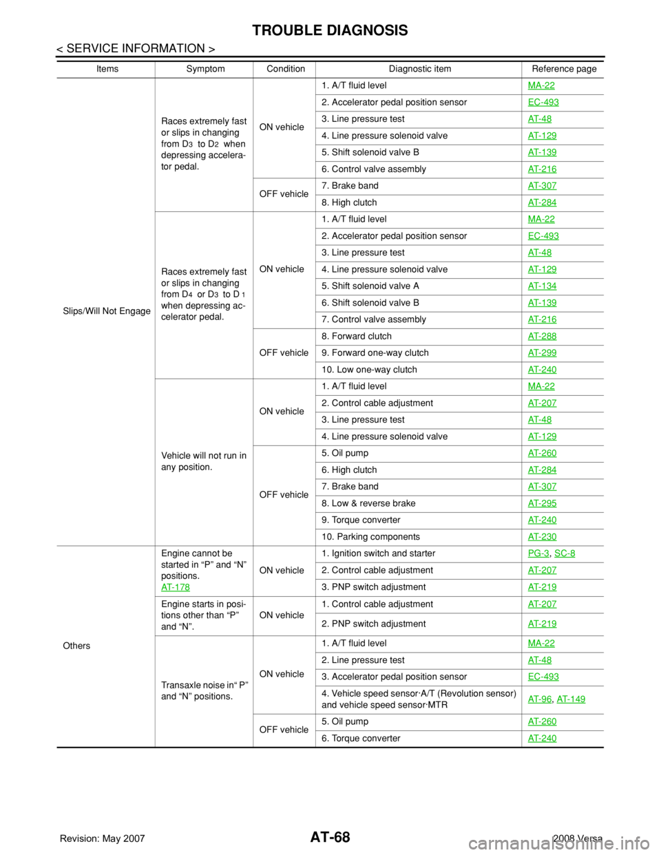
Slips/Will Not EngageRaces extremely fast
or slips in changing
from D
3 to D2 when
depressing accelera-
tor pedal. ON vehicle1. A/T fluid levelMA-22
2. Accelerator pedal position sensor EC-493
3. Line pressure testAT- 4 8
4. Line pressure solenoid valveAT- 1 2 9
5. Shift solenoid valve BAT- 1 3 9
6. Control valve assemblyAT- 2 1 6
OFF vehicle7. Brake bandAT- 3 0 78. High clutchAT- 2 8 4
Races extremely fast
or slips in changing
from D
4 or D3 to D 1
when depressing ac-
celerator pedal.ON vehicle1. A/T fluid levelMA-22
2. Accelerator pedal position sensorEC-493
3. Line pressure testAT- 4 8
4. Line pressure solenoid valveAT- 1 2 9
5. Shift solenoid valve AAT- 1 3 4
6. Shift solenoid valve BAT- 1 3 9
7. Control valve assemblyAT- 2 1 6
OFF vehicle8. Forward clutchAT- 2 8 89. Forward one-way clutchAT- 2 9 9
10. Low one-way clutchAT- 2 4 0
Vehicle will not run in
any position.ON vehicle1. A/T fluid levelMA-22
2. Control cable adjustmentAT- 2 0 7
3. Line pressure testAT- 4 8
4. Line pressure solenoid valveAT- 1 2 9
OFF vehicle5. Oil pumpAT- 2 6 0
6. High clutchAT- 2 8 4
7. Brake bandAT- 3 0 7
8. Low & reverse brakeAT- 2 9 5
9. Torque converterAT- 2 4 0
10. Parking componentsAT- 2 3 0
OthersEngine cannot be
started in “P” and “N”
positions.
AT- 1 7 8
ON vehicle1. Ignition switch and starterPG-3
, SC-8
2. Control cable adjustmentAT- 2 0 7
3. PNP switch adjustmentAT- 2 1 9
Engine starts in posi-
tions other than “P”
and “N”.ON vehicle1. Control cable adjustmentAT- 2 0 7
2. PNP switch adjustmentAT- 2 1 9
Transaxle noise in“ P”
and “N” positions.ON vehicle1. A/T fluid levelMA-22
2. Line pressure testAT- 4 8
3. Accelerator pedal position sensorEC-493
4. Vehicle speed sensor·A/T (Revolution sensor)
and vehicle speed sensor·MTRAT- 9 6, AT- 1 4 9
OFF vehicle5. Oil pumpAT- 2 6 06. Torque converterAT- 2 4 0
Items Symptom Condition Diagnostic item Reference page
Page 81 of 2771
TROUBLE DIAGNOSIS
AT-69
< SERVICE INFORMATION >
D
E
F
G
H
I
J
K
L
MA
B
AT
N
O
P
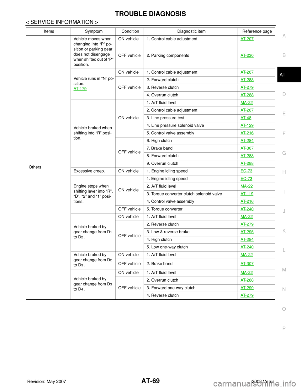
OthersVehicle moves when
changing into “P” po-
sition or parking gear
does not disengage
when shifted out of “P”
position.ON vehicle 1. Control cable adjustmentAT- 2 0 7
OFF vehicle 2. Parking componentsAT- 2 3 0
Vehicle runs in “N” po-
sition.
AT- 1 7 9
ON vehicle 1. Control cable adjustmentAT- 2 0 7
OFF vehicle2. Forward clutchAT- 2 8 83. Reverse clutchAT- 2 7 9
4. Overrun clutchAT- 2 8 8
Vehicle braked when
shifting into “R” posi-
tion.ON vehicle1. A/T fluid levelMA-22
2. Control cable adjustmentAT- 2 0 7
3. Line pressure testAT- 4 8
4. Line pressure solenoid valveAT- 1 2 9
5. Control valve assemblyAT- 2 1 6
OFF vehicle6. High clutchAT- 2 8 47. Brake band AT- 3 0 7
8. Forward clutchAT- 2 8 8
9. Overrun clutchAT- 2 8 8
Excessive creep. ON vehicle 1. Engine idling speedEC-73
Engine stops when
shifting lever into “R”,
“D”, “2” and “1” posi-
tions.ON vehicle1. Engine idling speedEC-732. A/T fluid levelMA-22
3. Torque converter clutch solenoid valveAT- 11 9
4. Control valve assemblyAT- 2 1 6
OFF vehicle 5. Torque converterAT- 2 4 0
Vehicle braked by
gear change from D
1
to D
2 .ON vehicle 1. A/T fluid levelMA-22OFF vehicle2. Reverse clutchAT- 2 7 93. Low & reverse brakeAT- 2 9 5
4. High clutchAT- 2 8 4
5. Low one-way clutchAT- 2 4 0
Vehicle braked by
gear change from D
2
to D
3 .ON vehicle 1. A/T fluid levelMA-22OFF vehicle 2. Brake bandAT- 3 0 7
Vehicle braked by
gear change from D
3
to D
4 .ON vehicle 1. A/T fluid levelMA-22OFF vehicle2. Overrun clutchAT- 2 8 83. Forward one-way clutchAT- 2 9 9
4. Reverse clutchAT- 2 7 9
Items Symptom Condition Diagnostic item Reference page
Page 82 of 2771
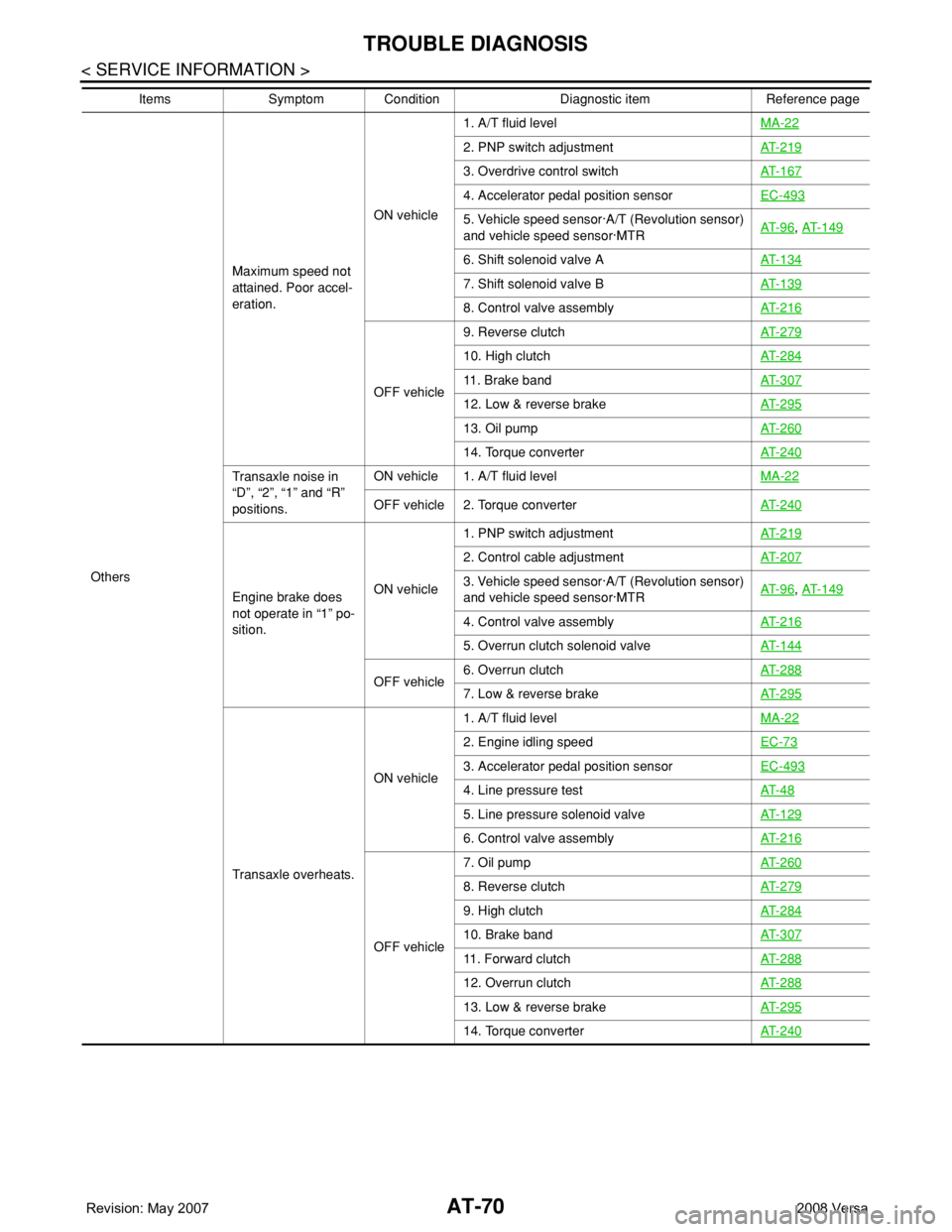
AT-70
< SERVICE INFORMATION >
TROUBLE DIAGNOSIS
OthersMaximum speed not
attained. Poor accel-
eration.ON vehicle1. A/T fluid levelMA-22
2. PNP switch adjustmentAT- 2 1 9
3. Overdrive control switchAT- 1 6 7
4. Accelerator pedal position sensorEC-493
5. Vehicle speed sensor·A/T (Revolution sensor)
and vehicle speed sensor·MTRAT- 9 6, AT- 1 4 9
6. Shift solenoid valve AAT- 1 3 4
7. Shift solenoid valve BAT- 1 3 9
8. Control valve assemblyAT- 2 1 6
OFF vehicle9. Reverse clutchAT- 2 7 9
10. High clutchAT- 2 8 4
11. Brake bandAT- 3 0 7
12. Low & reverse brakeAT- 2 9 5
13. Oil pumpAT- 2 6 0
14. Torque converterAT- 2 4 0
Transaxle noise in
“D”, “2”, “1” and “R”
positions.ON vehicle 1. A/T fluid levelMA-22
OFF vehicle 2. Torque converterAT- 2 4 0
Engine brake does
not operate in “1” po-
sition.ON vehicle1. PNP switch adjustmentAT- 2 1 9
2. Control cable adjustmentAT- 2 0 7
3. Vehicle speed sensor·A/T (Revolution sensor)
and vehicle speed sensor·MTRAT- 9 6, AT- 1 4 9
4. Control valve assemblyAT- 2 1 6
5. Overrun clutch solenoid valveAT- 1 4 4
OFF vehicle6. Overrun clutchAT- 2 8 87. Low & reverse brakeAT- 2 9 5
Transaxle overheats.ON vehicle1. A/T fluid levelMA-22
2. Engine idling speedEC-73
3. Accelerator pedal position sensorEC-493
4. Line pressure testAT- 4 8
5. Line pressure solenoid valveAT- 1 2 9
6. Control valve assemblyAT- 2 1 6
OFF vehicle7. Oil pumpAT- 2 6 0
8. Reverse clutchAT- 2 7 9
9. High clutchAT- 2 8 4
10. Brake bandAT- 3 0 7
11. Forward clutchAT- 2 8 8
12. Overrun clutchAT- 2 8 8
13. Low & reverse brakeAT- 2 9 5
14. Torque converterAT- 2 4 0
Items Symptom Condition Diagnostic item Reference page
Page 83 of 2771
TROUBLE DIAGNOSIS
AT-71
< SERVICE INFORMATION >
D
E
F
G
H
I
J
K
L
MA
B
AT
N
O
P
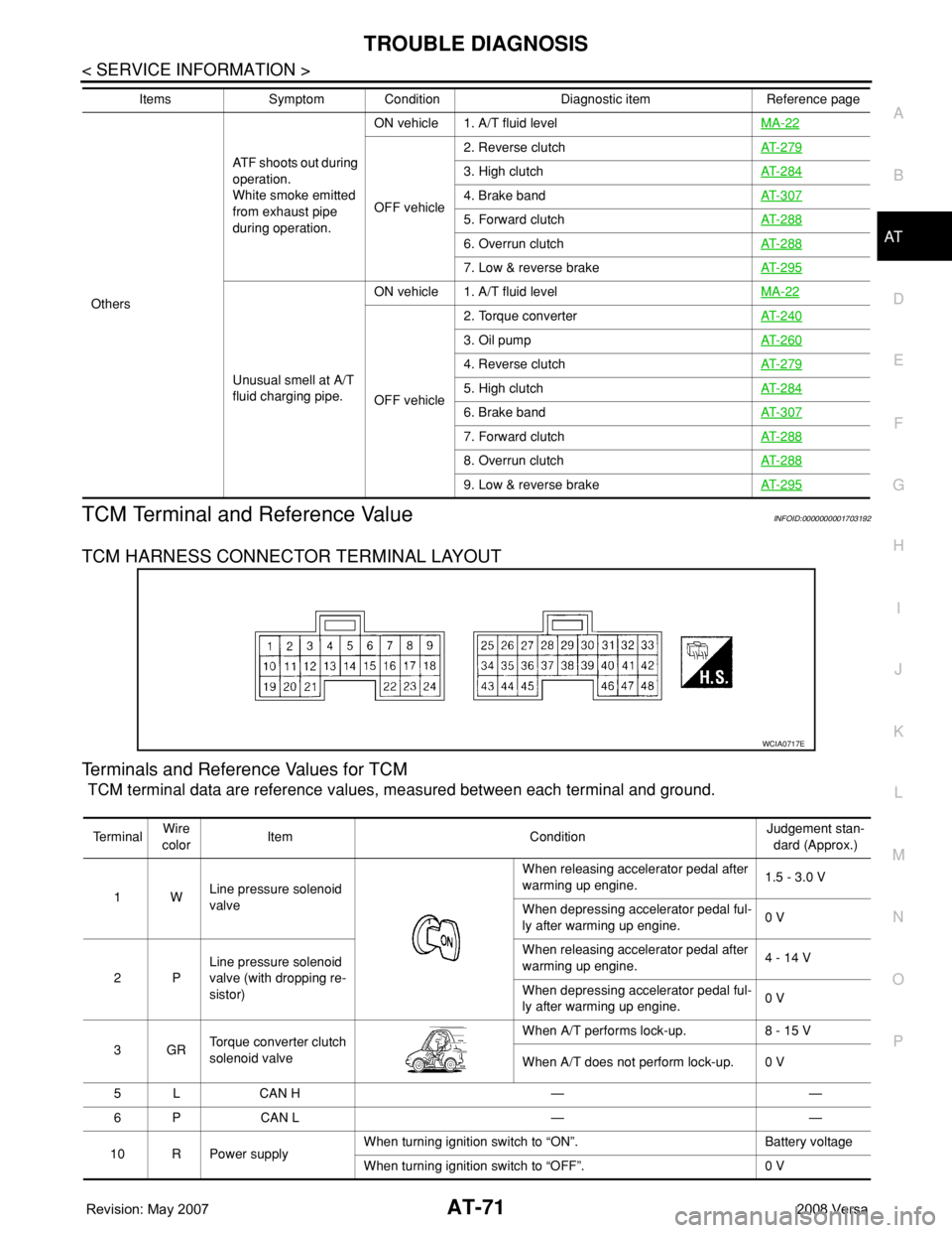
TCM Terminal and Reference ValueINFOID:0000000001703192
TCM HARNESS CONNECTOR TERMINAL LAYOUT
Terminals and Reference Values for TCM
TCM terminal data are reference values, measured between each terminal and ground.
OthersATF shoots out during
operation.
White smoke emitted
from exhaust pipe
during operation.ON vehicle 1. A/T fluid levelMA-22
OFF vehicle2. Reverse clutchAT- 2 7 9
3. High clutchAT- 2 8 4
4. Brake bandAT- 3 0 7
5. Forward clutchAT- 2 8 8
6. Overrun clutchAT- 2 8 8
7. Low & reverse brakeAT- 2 9 5
Unusual smell at A/T
fluid charging pipe.ON vehicle 1. A/T fluid levelMA-22
OFF vehicle2. Torque converterAT- 2 4 0
3. Oil pumpAT- 2 6 0
4. Reverse clutchAT- 2 7 9
5. High clutchAT- 2 8 4
6. Brake bandAT- 3 0 7
7. Forward clutchAT- 2 8 8
8. Overrun clutchAT- 2 8 8
9. Low & reverse brakeAT- 2 9 5
Items Symptom Condition Diagnostic item Reference page
WCIA0717E
Te r m i n a lWire
colorItem ConditionJudgement stan-
dard (Approx.)
1WLine pressure solenoid
valveWhen releasing accelerator pedal after
warming up engine.1.5 - 3.0 V
When depressing accelerator pedal ful-
ly after warming up engine.0 V
2PLine pressure solenoid
valve (with dropping re-
sistor)When releasing accelerator pedal after
warming up engine.4 - 14 V
When depressing accelerator pedal ful-
ly after warming up engine.0 V
3GRTorque converter clutch
solenoid valveWhen A/T performs lock-up. 8 - 15 V
When A/T does not perform lock-up. 0 V
5 L CAN H — —
6 P CAN L — —
10 R Power supplyWhen turning ignition switch to “ON”. Battery voltage
When turning ignition switch to “OFF”. 0 V
Page 85 of 2771
TROUBLE DIAGNOSIS
AT-73
< SERVICE INFORMATION >
D
E
F
G
H
I
J
K
L
MA
B
AT
N
O
P
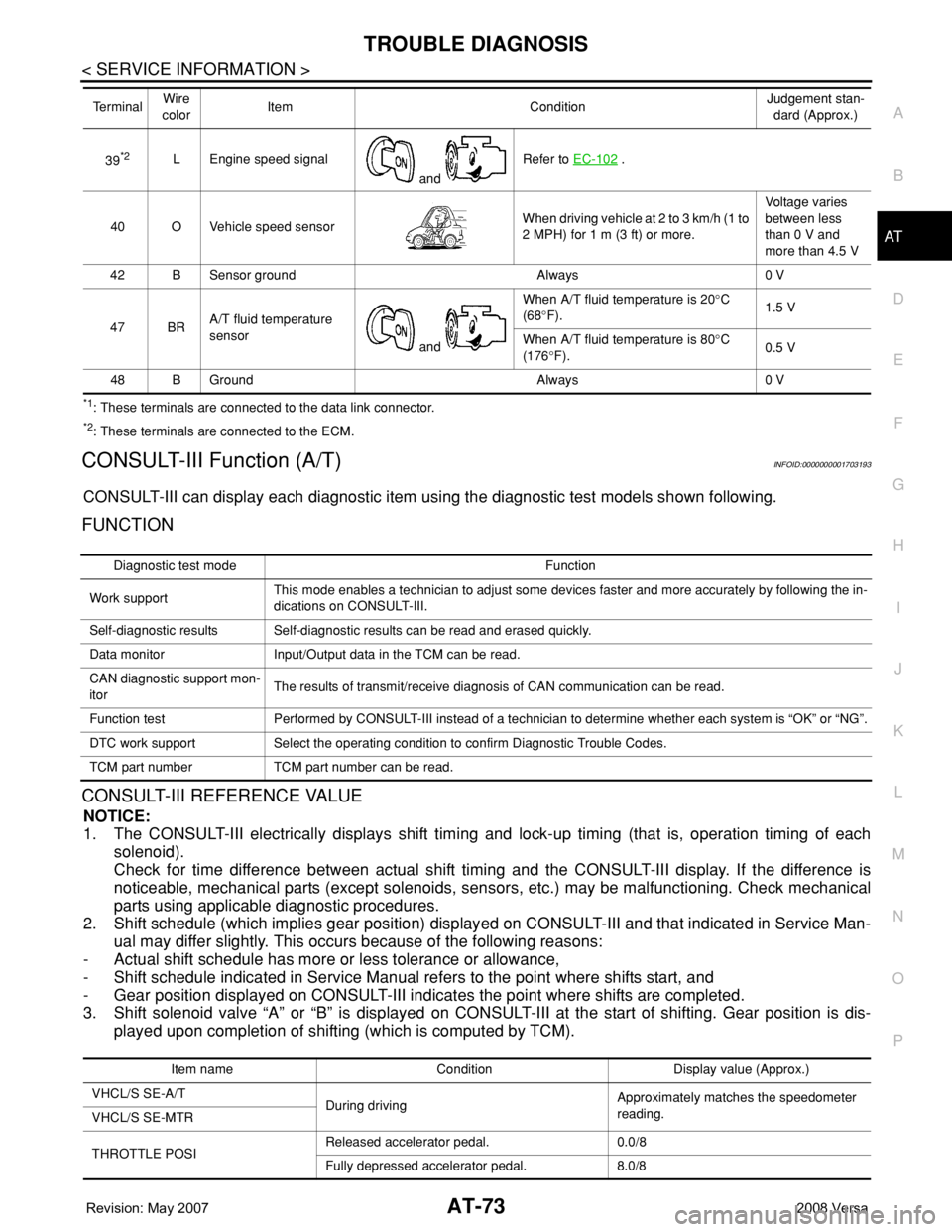
*1: These terminals are connected to the data link connector.
*2: These terminals are connected to the ECM.
CONSULT-III Function (A/T)INFOID:0000000001703193
CONSULT-III can display each diagnostic item using the diagnostic test models shown following.
FUNCTION
CONSULT-III REFERENCE VALUE
NOTICE:
1. The CONSULT-III electrically displays shift timing and lock-up timing (that is, operation timing of each
solenoid).
Check for time difference between actual shift timing and the CONSULT-III display. If the difference is
noticeable, mechanical parts (except solenoids, sensors, etc.) may be malfunctioning. Check mechanical
parts using applicable diagnostic procedures.
2. Shift schedule (which implies gear position) displayed on CONSULT-III and that indicated in Service Man-
ual may differ slightly. This occurs because of the following reasons:
- Actual shift schedule has more or less tolerance or allowance,
- Shift schedule indicated in Service Manual refers to the point where shifts start, and
- Gear position displayed on CONSULT-III indicates the point where shifts are completed.
3. Shift solenoid valve “A” or “B” is displayed on CONSULT-III at the start of shifting. Gear position is dis-
played upon completion of shifting (which is computed by TCM).
39*2L Engine speed signal
and Refer to EC-102 .
40 O Vehicle speed sensorWhen driving vehicle at 2 to 3 km/h (1 to
2 MPH) for 1 m (3 ft) or more.Voltage varies
between less
than 0 V and
more than 4.5 V
42 B Sensor ground Always 0 V
47 BRA/T fluid temperature
sensor
and When A/T fluid temperature is 20°C
(68°F).1.5 V
When A/T fluid temperature is 80°C
(176°F).0.5 V
48 B Ground Always 0 V Te r m i n a lWire
colorItem ConditionJudgement stan-
dard (Approx.)
Diagnostic test mode Function
Work supportThis mode enables a technician to adjust some devices faster and more accurately by following the in-
dications on CONSULT-III.
Self-diagnostic results Self-diagnostic results can be read and erased quickly.
Data monitor Input/Output data in the TCM can be read.
CAN diagnostic support mon-
itorThe results of transmit/receive diagnosis of CAN communication can be read.
Function test Performed by CONSULT-III instead of a technician to determine whether each system is “OK” or “NG”.
DTC work support Select the operating condition to confirm Diagnostic Trouble Codes.
TCM part number TCM part number can be read.
Item name Condition Display value (Approx.)
VHCL/S SE-A/T
During drivingApproximately matches the speedometer
reading.
VHCL/S SE-MTR
THROTTLE POSIReleased accelerator pedal. 0.0/8
Fully depressed accelerator pedal. 8.0/8