2008 NISSAN TIIDA replace battery
[x] Cancel search: replace batteryPage 2723 of 2771

TROUBLE DIAGNOSES
WT-15
< SERVICE INFORMATION >
C
D
F
G
H
I
J
K
L
MA
B
WT
N
O
P
3. Reconnect harness connector.
OK or NG
OK >> GO TO 4.
NG >> Repair or replace damaged parts.
4.CHECK TRANSMITTER ACTIVATION TOOL
Check transmitter activation tool battery.
OK or NG
OK >> Carry out self-diagnosis.
NG >> Replace battery in transmitter activation tool.
Self-DiagnosisINFOID:0000000001703761
DESCRIPTION
During driving, the tire pressure monitoring system receives the signal transmitted from the transmitter
installed in each wheel, and turns on the low tire pressure warning lamp when the tire pressure becomes low.
The control unit (BCM) for this system has pressure judgement and self-diagnosis functions.
FUNCTION
When the tire pressure monitoring system detects low inflation pressure or an internal malfunction, the low tire
pressure warning lamp in the combination meter comes on. The malfunction location is indicated by the low
tire pressure warning lamp flashing and the buzzer sounding.
CONSULT-III Application to Tire Pressure Monitoring System
× : Applicable
– : Not applicable
Self-Diagnostic Results Mode
ITEM SELF-DIAGNOSTIC RESULTS DATA MONITOR
Front - Left transmitter××
Front - Right transmitter××
Rear - Left transmitter××
Rear - Right transmitter××
Warning lamp —×
Vehicle speed××
Buzzer (in combination meter) —×
CAN Communication××
Diagnostic item Diagnostic item is detected when ···Reference
page
FLAT - TIRE - FL [C1704]
FLAT - TIRE - FR [C1705]
FLAT - TIRE - RR [C1706]
FLAT - TIRE - RL [C1707]FL tire pressure 193 kPa (2.0 kg/cm
2 , 28 psi) or less
FR tire pressure 193 kPa (2.0 kg/cm2 , 28 psi) or less
RR tire pressure 193 kPa (2.0 kg/cm2 , 28 psi) or less
RL tire pressure 193 kPa (2.0 kg/cm2 , 28 psi) or less—
[NO-DATA] - FL [C1708]
[NO-DATA] - FR [C1709]
[NO-DATA] - RR [C1710]
[NO-DATA] - RL [C1711]Data from FL transmitter cannot be received.
Data from FR transmitter cannot be received.
Data from RR transmitter cannot be received.
Data from RL transmitter cannot be received.WT-18
[CHECKSUM- ERR] - FL [C1712]
[CHECKSUM- ERR] - FR [C1713]
[CHECKSUM- ERR] - RR [C1714]
[CHECKSUM- ERR] - RL [C1715]Checksum data from FL transmitter is malfunctioning.
Checksum data from FR transmitter is malfunctioning.
Checksum data from RR transmitter is malfunctioning.
Checksum data from RL transmitter is malfunctioning.WT-18
[PRESSDATA- ERR] - FL [C1716]
[PRESSDATA- ERR] - FR [C1717]
[PRESSDATA- ERR] - RR [C1718]
[PRESSDATA- ERR] - RL [C1719]Air pressure data from FL transmitter is malfunctioning.
Air pressure data from FR transmitter is malfunctioning.
Air pressure data from RR transmitter is malfunctioning.
Air pressure data from RL transmitter is malfunctioning.WT-19
Page 2728 of 2771
WT-20
< SERVICE INFORMATION >
TROUBLE DIAGNOSIS FOR SYMPTOMS
TROUBLE DIAGNOSIS FOR SYMPTOMS
Low Tire Pressure Warning Lamp Does Not Come On When Ignition Switch Is Turned
On
INFOID:0000000001703767
DIAGNOSTIC PROCEDURE
1.SELF-DIAGNOSTIC RESULT CHECK
Using CONSULT-III, check display contents in self-diagnostic results.
Is "CAN COMM CIRCUIT" displayed in the self-diagnosis display items?
YES >> Malfunction in CAN communication system. GO TO LAN-12, "CAN Diagnosis with CONSULT-
III".
NO >> GO TO 2.
2.CHECK COMBINATION METER
Check combination meter operation. Refer to DI-11, "
Self-Diagnosis Mode of Combination Meter".
Inspection results OK?
OK >> GO TO 3.
NG >> Replace combination meter. Refer to IP-11, "
Removal and Installation".
3.CHECK LOW TIRE PRESSURE WARNING LAMP
Disconnect BCM harness connector.
Does the low tire pressure warning lamp activate?
YES >> Replace BCM. Refer to BCS-18, "Removal and Installation of BCM".
NO >> Check combination meter operation. Refer to DI-11, "
Self-Diagnosis Mode of Combination
Meter".
Low Tire Pressure Warning Lamp Stays On When Ignition Switch Is Turned On
INFOID:0000000001703768
DIAGNOSTIC PROCEDURE
1.CHECK BCM CONNECTORS
1. Turn ignition switch OFF.
2. Disconnect BCM harness connectors M18 and M20.
3. Check terminals for damage or loose connections.
Inspection results OK?
OK >> GO TO 2.
NG >> Repair or replace damaged parts.
2.CHECK BCM POWER SUPPLY CIRCUIT (BAT)
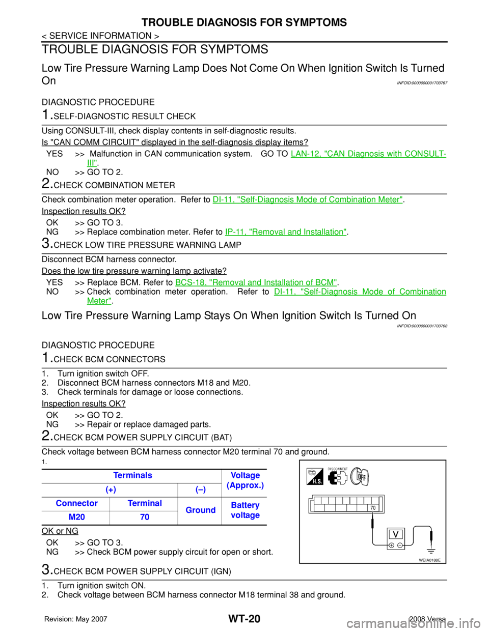
Check voltage between BCM harness connector M20 terminal 70 and ground.
1.
OK or NG
OK >> GO TO 3.
NG >> Check BCM power supply circuit for open or short.
3.CHECK BCM POWER SUPPLY CIRCUIT (IGN)
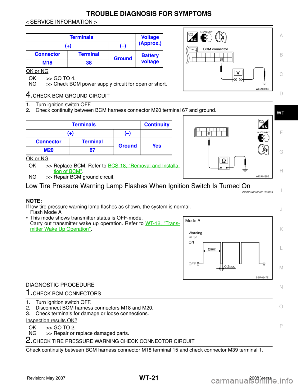
1. Turn ignition switch ON.
2. Check voltage between BCM harness connector M18 terminal 38 and ground.Terminals Voltage
(Approx.)
(+) (–)
Connector Terminal
GroundBattery
voltage
M20 70
WEIA0188E
Page 2729 of 2771
TROUBLE DIAGNOSIS FOR SYMPTOMS
WT-21
< SERVICE INFORMATION >
C
D
F
G
H
I
J
K
L
MA
B
WT
N
O
P
OK or NG
OK >> GO TO 4.
NG >> Check BCM power supply circuit for open or short.
4.CHECK BCM GROUND CIRCUIT
1. Turn ignition switch OFF.
2. Check continuity between BCM harness connector M20 terminal 67 and ground.
OK or NG
OK >> Replace BCM. Refer to BCS-18, "Removal and Installa-
tion of BCM".
NG >> Repair BCM ground circuit.
Low Tire Pressure Warning Lamp Flashes When Ignition Switch Is Turned On
INFOID:0000000001703769
NOTE:
If low tire pressure warning lamp flashes as shown, the system is normal.
Flash Mode A
• This mode shows transmitter status is OFF-mode.
Carry out transmitter wake up operation. Refer to WT-12, "
Trans-
mitter Wake Up Operation".
DIAGNOSTIC PROCEDURE
1.CHECK BCM CONNECTORS
1. Turn ignition switch OFF.
2. Disconnect BCM harness connectors M18 and M20.
3. Check terminals for damage or loose connections.
Inspection results OK?
OK >> GO TO 2.
NG >> Repair or replace damaged parts.
2.CHECK TIRE PRESSURE WARNING CHECK CONNECTOR CIRCUIT
Check continuity between BCM harness connector M18 terminal 15 and check connector M39 terminal 1. Terminals Voltage
(Approx.)
(+) (–)
Connector Terminal
GroundBattery
voltage
M18 38
WEIA0038E
Terminals Continuity
(+) (–)
Connector Terminal
Ground Yes
M20 67
WEIA0189E
SEIA0347E
Page 2746 of 2771
FRONT WIPER AND WASHER SYSTEM
WW-13
< SERVICE INFORMATION >
C
D
E
F
G
H
I
J
L
MA
B
WW
N
O
P
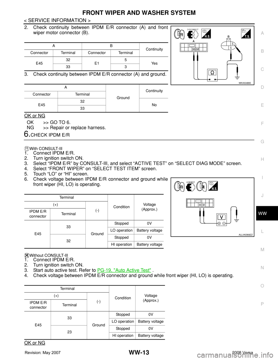
2. Check continuity between IPDM E/R connector (A) and front
wiper motor connector (B).
3. Check continuity between IPDM E/R connector (A) and ground.
OK or NG
OK >> GO TO 6.
NG >> Repair or replace harness.
6.CHECK IPDM E/R
With CONSULT-lIl
1. Connect IPDM E/R.
2. Turn ignition switch ON.
3. Select “IPDM E/R” by CONSULT-III, and select “ACTIVE TEST” on “SELECT DIAG MODE” screen.
4. Select “FRONT WIPER” on “SELECT TEST ITEM” screen.
5. Touch “LO” or “HI” screen.
6. Check voltage between IPDM E/R connector and ground while
front wiper (HI, LO) is operating.
Without CONSULT-llI1. Connect IPDM E/R.
2. Turn ignition switch ON.
3. Start auto active test. Refer to PG-19, "
Auto Active Test" .
4. Check voltage between IPDM E/R connector and ground while front wiper (HI, LO) is operating.
OK or NG
AB
Continuity
Connector Terminal Connector Terminal
E4532
E15
Ye s
33 3
A
GroundContinuity
Connector Terminal
E4532
No
33
WKIA5489E
Te r m i n a l
ConditionVo l ta g e
(Approx.) (+)
(-)
IPDM E/R
connectorTe r m i n a l
E4533
GroundStopped 0V
LO operation Battery voltage
32Stopped 0V
HI operation Battery voltage
Te r m i n a l
ConditionVol tag e
(Approx.) (+)
(-)
IPDM E/R
connectorTe r m i n a l
E4533
GroundStopped 0V
LO operation Battery voltage
23Stopped 0V
HI operation Battery voltage
ALLIA0368ZZ
Page 2747 of 2771
WW-14
< SERVICE INFORMATION >
FRONT WIPER AND WASHER SYSTEM
OK >> Replace front wiper motor. Refer to WW-19, "Removal and Installation of Front Wiper Drive
Assembly" .
NG >> Replace IPDM E/R. Refer to PG-26, "
Removal and Installation of IPDM E/R" .
Front Wiper Does Not Return to Stop Position (After Front Wiper Operate for 10 Sec-
onds, They Stop for 20 Seconds, and After Repeating the Operation Five Times, They
Become Inoperative)
INFOID:0000000001704547
CAUTION:
• When auto-stop signal has not varied for 10 seconds or longer while IPDM E/R is operating front wip-
ers, IPDM E/R considers that front wipers are locked, and stops wiper output. That causes this symp-
tom.
• This status can be checked by “DATA MONITOR” of “IPDM E/R” on which “WIPER PROT” item
shows “BLOCK”.
1.CHECK FRONT WIPER STOP SIGNAL
With CONSULT-lIl
Select “IPDM E/R” on CONSULT-III. With “DATA MONITOR”, make sure that “WIP AUTO STOP” turns “ACT
P” - “STOP P” linked with wiper operation.
Without CONSULT-llI
GO TO 2.
OK or NG
OK >> Replace IPDM E/R. Refer to PG-26, "Removal and Installation of IPDM E/R" .
NG >> GO TO 2.
2.CHECK IPDM E/R
1. Turn ignition switch ON.
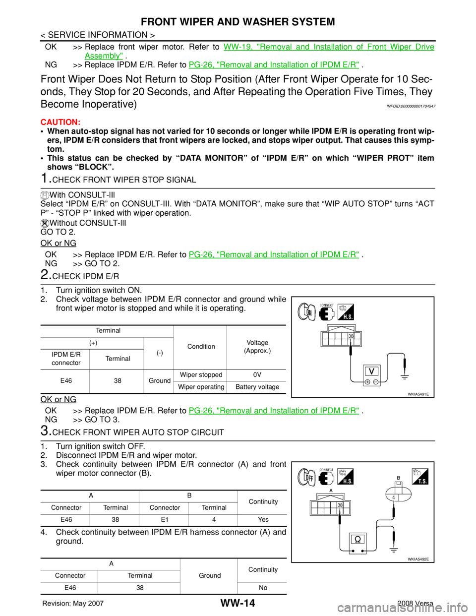
2. Check voltage between IPDM E/R connector and ground while
front wiper motor is stopped and while it is operating.
OK or NG
OK >> Replace IPDM E/R. Refer to PG-26, "Removal and Installation of IPDM E/R" .
NG >> GO TO 3.
3.CHECK FRONT WIPER AUTO STOP CIRCUIT
1. Turn ignition switch OFF.
2. Disconnect IPDM E/R and wiper motor.
3. Check continuity between IPDM E/R connector (A) and front
wiper motor connector (B).
4. Check continuity between IPDM E/R harness connector (A) and
ground.
Te r m i n a l
ConditionVo l ta g e
(Approx.) (+)
(-)
IPDM E/R
connectorTe r m i n a l
E46 38 GroundWiper stopped 0V
Wiper operating Battery voltage
WKIA5491E
AB
Continuity
Connector Terminal Connector Terminal
E46 38 E1 4 Yes
A
GroundContinuity
Connector Terminal
E46 38 No
WKIA5492E
Page 2748 of 2771
FRONT WIPER AND WASHER SYSTEM
WW-15
< SERVICE INFORMATION >
C
D
E
F
G
H
I
J
L
MA
B
WW
N
O
P
OK or NG
OK >> Replace front wiper motor. Refer to WW-19, "Removal and Installation of Front Wiper Drive
Assembly" .
NG >> Repair or replace harness.
Only Front Wiper Low Does Not OperateINFOID:0000000001704548
1.ACTIVE TEST
With CONSULT-lIl
1. Select “IPDM E/R” on CONSULT-III, and select “ACTIVE TEST” on “SELECT DIAG MODE” screen.
2. Select “FRONT WIPER” on “SELECT TEST ITEM” screen.
3. Touch “LO” screen.
Without CONSULT-lIl
Start auto active test. Refer to PG-19, "
Auto Active Test" .
Does front wiper operate normally?
YES >> Refer to LT-63, "Combination Switch Inspection" .
NO >> GO TO 2.
2.CHECK FRONT WIPER MOTOR CIRCUIT
1. Turn ignition switch OFF.
2. Disconnect IPDM E/R and front wiper motor.
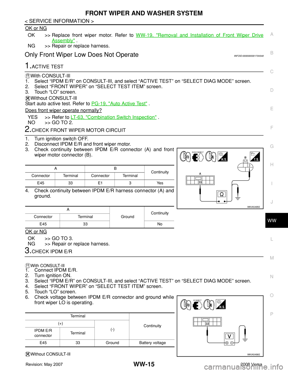
3. Check continuity between IPDM E/R connector (A) and front
wiper motor connector (B).
4. Check continuity between IPDM E/R harness connector (A) and
ground.
OK or NG
OK >> GO TO 3.
NG >> Repair or replace harness.
3.CHECK IPDM E/R
With CONSULT-lIl
1. Connect IPDM E/R.
2. Turn ignition ON.
3. Select “IPDM E/R” on CONSULT-III, and select “ACTIVE TEST” on “SELECT DIAG MODE” screen.
4. Select “FRONT WIPER” on “SELECT TEST ITEM” screen.
5. Touch “LO” screen.
6. Check voltage between IPDM E/R connector and ground while
front wiper LO is operating.
Without CONSULT-lIl
AB
Continuity
Connector Terminal Connector Terminal
E45 33 E1 3 Yes
A
GroundContinuity
Connector Terminal
E45 33 No
WKIA5495E
Te r m i n a l
Continuity (+)
(-)
IPDM E/R
connectorTe r m i n a l
E45 33 Ground Battery voltage
WKIA5496E
Page 2749 of 2771
WW-16
< SERVICE INFORMATION >
FRONT WIPER AND WASHER SYSTEM
1. Connect IPDM E/R.
2. Turn ignition ON.
3. Start auto active test. Refer to PG-19, "
Auto Active Test" .
4. Check voltage between IPDM E/R connector and ground while front wiper LO is operating.
OK or NG
OK >> Replace front wiper motor. Refer to WW-19, "Removal and Installation of Front Wiper Drive
Assembly" .
NG >> Replace IPDM E/R. Refer to PG-26, "
Removal and Installation of IPDM E/R" .
Only Front Wiper High Does Not OperateINFOID:0000000001704549
1.ACTIVE TEST
With CONSULT-Ill
1. Select “IPDM E/R” on CONSULT-III, and select “ACTIVE TEST” on “SELECT DIAG MODE” screen.
2. Select “FRONT WIPER” on “SELECT TEST ITEM” screen.
3. Touch “HI” screen.
Without CONSULT-lIl
Start auto active test. Refer to PG-19, "
Auto Active Test" .
Does front wiper operate normally?
YES >> Refer to LT-63, "Combination Switch Inspection" .
NO >> GO TO 2.
2.CHECK FRONT WIPER MOTOR CIRCUIT
1. Turn ignition switch OFF.
2. Disconnect IPDM E/R connector E45 and front wiper motor connector E1.
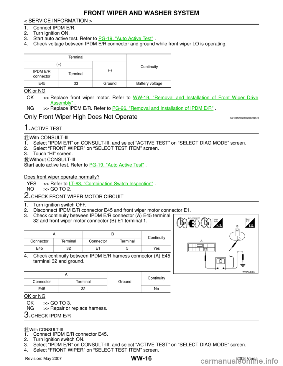
3. Check continuity between IPDM E/R connector (A) E45 terminal
32 and front wiper motor connector (B) E1 terminal 1.
4. Check continuity between IPDM E/R harness connector (A) E45
terminal 32 and ground.
OK or NG
OK >> GO TO 3.
NG >> Repair or replace harness.
3.CHECK IPDM E/R
With CONSULT-lIl
1. Connect IPDM E/R connector E45.
2. Turn ignition switch ON.
3. Select “IPDM E/R” on CONSULT-III, and select “ACTIVE TEST” on “SELECT DIAG MODE” screen.
4. Select “FRONT WIPER” on “SELECT TEST ITEM” screen.
Te r m i n a l
Continuity (+)
(-)
IPDM E/R
connectorTe r m i n a l
E45 33 Ground Battery voltage
AB
Continuity
Connector Terminal Connector Terminal
E45 32 E1 5 Yes
A
GroundContinuity
Connector Terminal
E45 32 No
WKIA5498E
Page 2750 of 2771
FRONT WIPER AND WASHER SYSTEM
WW-17
< SERVICE INFORMATION >
C
D
E
F
G
H
I
J
L
MA
B
WW
N
O
P
5. Touch “HI” screen.
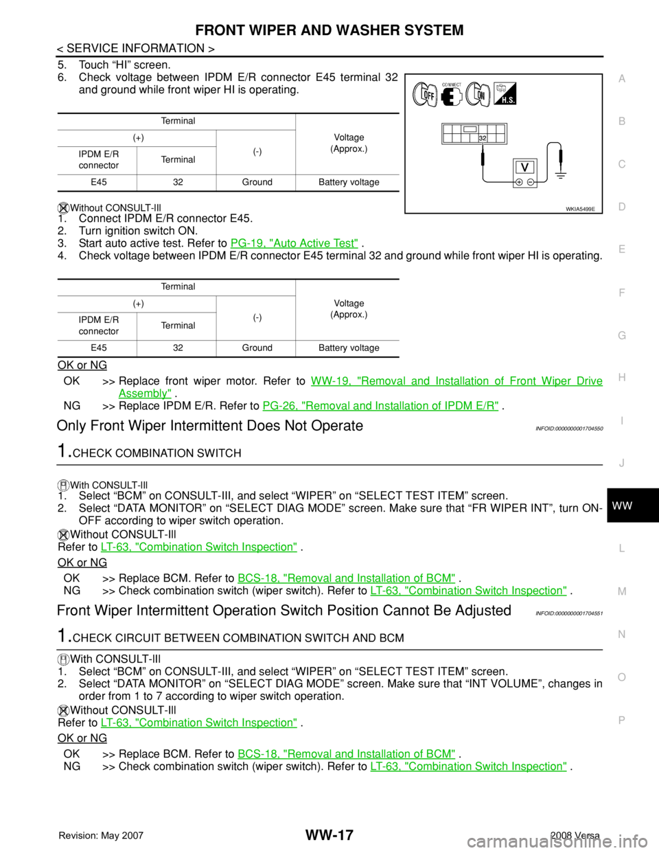
6. Check voltage between IPDM E/R connector E45 terminal 32
and ground while front wiper HI is operating.
Without CONSULT-lIl
1. Connect IPDM E/R connector E45.
2. Turn ignition switch ON.
3. Start auto active test. Refer to PG-19, "
Auto Active Test" .
4. Check voltage between IPDM E/R connector E45 terminal 32 and ground while front wiper HI is operating.
OK or NG
OK >> Replace front wiper motor. Refer to WW-19, "Removal and Installation of Front Wiper Drive
Assembly" .
NG >> Replace IPDM E/R. Refer to PG-26, "
Removal and Installation of IPDM E/R" .
Only Front Wiper Intermittent Does Not OperateINFOID:0000000001704550
1.CHECK COMBINATION SWITCH
With CONSULT-lIl1. Select “BCM” on CONSULT-III, and select “WIPER” on “SELECT TEST ITEM” screen.
2. Select “DATA MONITOR” on “SELECT DIAG MODE” screen. Make sure that “FR WIPER INT”, turn ON-
OFF according to wiper switch operation.
Without CONSULT-Ill
Refer to LT-63, "
Combination Switch Inspection" .
OK or NG
OK >> Replace BCM. Refer to BCS-18, "Removal and Installation of BCM" .
NG >> Check combination switch (wiper switch). Refer to LT-63, "
Combination Switch Inspection" .
Front Wiper Intermittent Operation Switch Position Cannot Be AdjustedINFOID:0000000001704551
1.CHECK CIRCUIT BETWEEN COMBINATION SWITCH AND BCM
With CONSULT-lIl
1. Select “BCM” on CONSULT-III, and select “WIPER” on “SELECT TEST ITEM” screen.
2. Select “DATA MONITOR” on “SELECT DIAG MODE” screen. Make sure that “INT VOLUME”, changes in
order from 1 to 7 according to wiper switch operation.
Without CONSULT-Ill
Refer to LT-63, "
Combination Switch Inspection" .
OK or NG
OK >> Replace BCM. Refer to BCS-18, "Removal and Installation of BCM" .
NG >> Check combination switch (wiper switch). Refer to LT-63, "
Combination Switch Inspection" .
Te r m i n a l
Vo l ta g e
(Approx.) (+)
(-)
IPDM E/R
connectorTe r m i n a l
E45 32 Ground Battery voltage
Te r m i n a l
Vo l ta g e
(Approx.) (+)
(-)
IPDM E/R
connectorTe r m i n a l
E45 32 Ground Battery voltage
WKIA5499E