Page 1937 of 2771
GW-36
< SERVICE INFORMATION >
POWER WINDOW SYSTEM
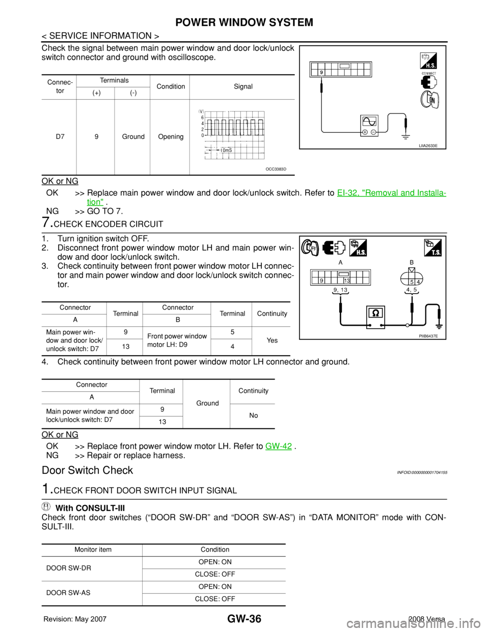
Check the signal between main power window and door lock/unlock
switch connector and ground with oscilloscope.
OK or NG
OK >> Replace main power window and door lock/unlock switch. Refer to EI-32, "Removal and Installa-
tion" .
NG >> GO TO 7.
7.CHECK ENCODER CIRCUIT
1. Turn ignition switch OFF.
2. Disconnect front power window motor LH and main power win-
dow and door lock/unlock switch.
3. Check continuity between front power window motor LH connec-
tor and main power window and door lock/unlock switch connec-
tor.
4. Check continuity between front power window motor LH connector and ground.
OK or NG
OK >> Replace front power window motor LH. Refer to GW-42 .
NG >> Repair or replace harness.
Door Switch CheckINFOID:0000000001704155
1.CHECK FRONT DOOR SWITCH INPUT SIGNAL
With CONSULT-III
Check front door switches (“DOOR SW-DR” and “DOOR SW-AS”) in “DATA MONITOR” mode with CON-
SULT-III.
Connec-
torTe r m i n a l s
Condition Signal
(+) (-)
D7 9 Ground Opening
LIIA2633E
OCC3383D
Connector
Te r m i n a lConnector
Terminal Continuity
AB
Main power win-
dow and door lock/
unlock switch: D79
Front power window
motor LH: D95
Ye s
13 4
Connector
Te r m i n a l
GroundContinuity
A
Main power window and door
lock/unlock switch: D79
No
13
PIIB6437E
Monitor item Condition
DOOR SW-DROPEN: ON
CLOSE: OFF
DOOR SW-ASOPEN: ON
CLOSE: OFF
Page 1939 of 2771
GW-38
< SERVICE INFORMATION >
POWER WINDOW SYSTEM
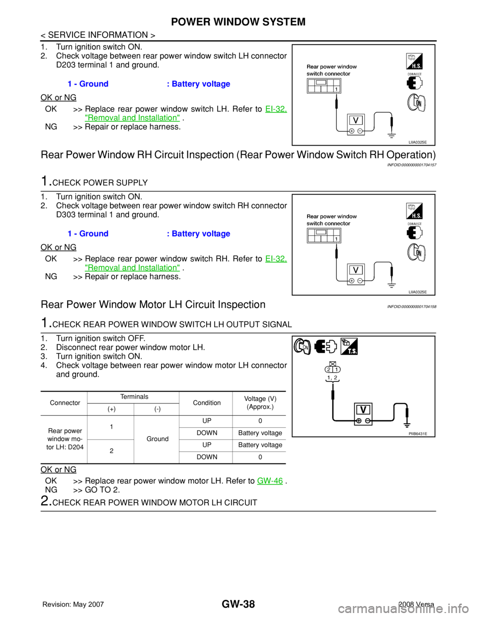
1. Turn ignition switch ON.
2. Check voltage between rear power window switch LH connector
D203 terminal 1 and ground.
OK or NG
OK >> Replace rear power window switch LH. Refer to EI-32,
"Removal and Installation" .
NG >> Repair or replace harness.
Rear Power Window RH Circuit Inspection (Rear Power Window Switch RH Operation)
INFOID:0000000001704157
1.CHECK POWER SUPPLY
1. Turn ignition switch ON.
2. Check voltage between rear power window switch RH connector
D303 terminal 1 and ground.
OK or NG
OK >> Replace rear power window switch RH. Refer to EI-32,
"Removal and Installation" .
NG >> Repair or replace harness.
Rear Power Window Motor LH Circuit InspectionINFOID:0000000001704158
1.CHECK REAR POWER WINDOW SWITCH LH OUTPUT SIGNAL
1. Turn ignition switch OFF.
2. Disconnect rear power window motor LH.
3. Turn ignition switch ON.
4. Check voltage between rear power window motor LH connector
and ground.
OK or NG
OK >> Replace rear power window motor LH. Refer to GW-46 .
NG >> GO TO 2.
2.CHECK REAR POWER WINDOW MOTOR LH CIRCUIT1 - Ground : Battery voltage
LIIA0325E
1 - Ground : Battery voltage
LIIA0325E
ConnectorTe r m i n a l s
ConditionVoltage (V)
(Approx.)
(+) (-)
Rear power
window mo-
tor LH: D2041
GroundUP 0
DOWN Battery voltage
2UP Battery voltage
DOWN 0
PIIB6431E
Page 1940 of 2771
POWER WINDOW SYSTEM
GW-39
< SERVICE INFORMATION >
C
D
E
F
G
H
J
K
L
MA
B
GW
N
O
P
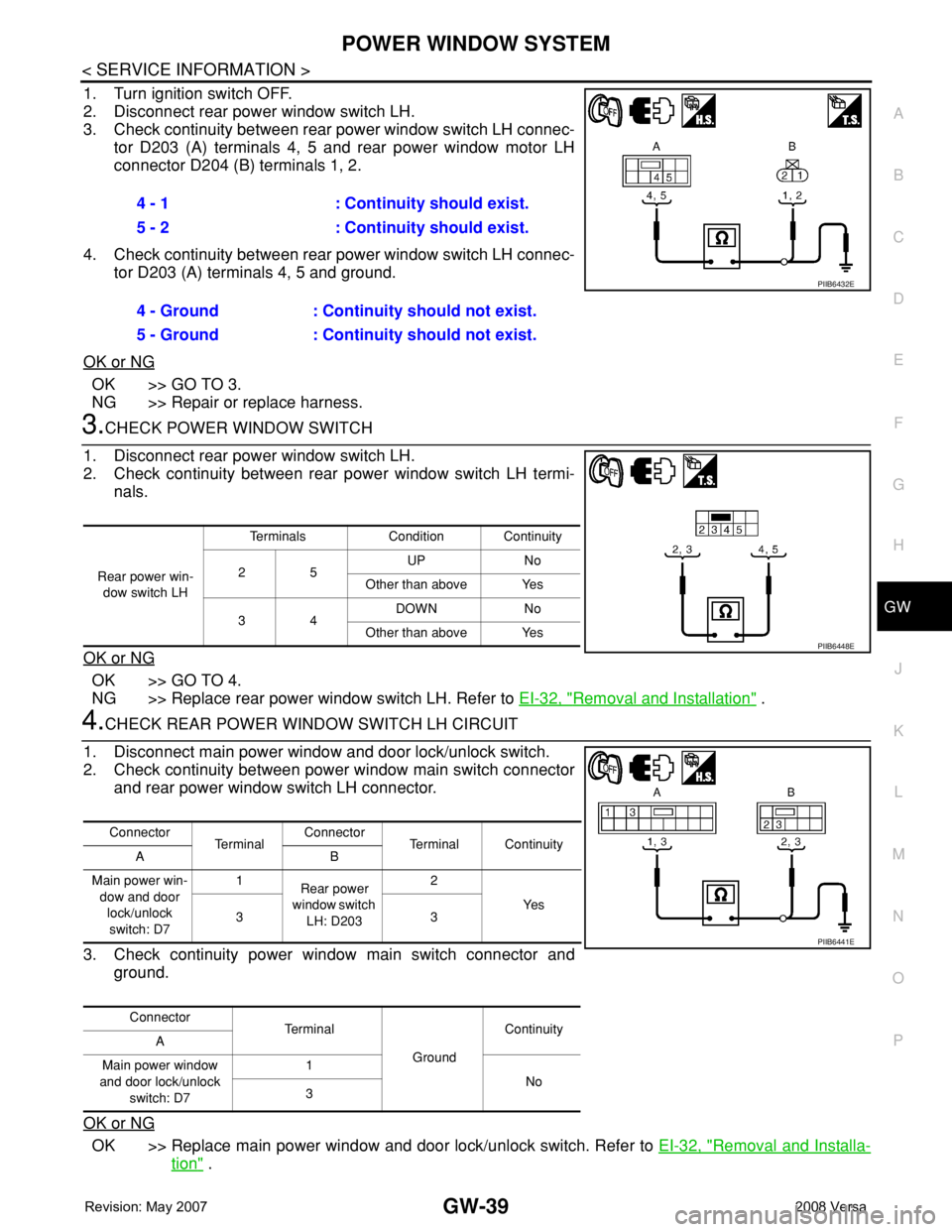
1. Turn ignition switch OFF.
2. Disconnect rear power window switch LH.
3. Check continuity between rear power window switch LH connec-
tor D203 (A) terminals 4, 5 and rear power window motor LH
connector D204 (B) terminals 1, 2.
4. Check continuity between rear power window switch LH connec-
tor D203 (A) terminals 4, 5 and ground.
OK or NG
OK >> GO TO 3.
NG >> Repair or replace harness.
3.CHECK POWER WINDOW SWITCH
1. Disconnect rear power window switch LH.
2. Check continuity between rear power window switch LH termi-
nals.
OK or NG
OK >> GO TO 4.
NG >> Replace rear power window switch LH. Refer to EI-32, "
Removal and Installation" .
4.CHECK REAR POWER WINDOW SWITCH LH CIRCUIT
1. Disconnect main power window and door lock/unlock switch.
2. Check continuity between power window main switch connector
and rear power window switch LH connector.
3. Check continuity power window main switch connector and
ground.
OK or NG
OK >> Replace main power window and door lock/unlock switch. Refer to EI-32, "Removal and Installa-
tion" . 4 - 1 : Continuity should exist.
5 - 2 : Continuity should exist.
4 - Ground : Continuity should not exist.
5 - Ground : Continuity should not exist.
PIIB6432E
Rear power win-
dow switch LHTerminals Condition Continuity
25UP No
Other than above Yes
34DOWN No
Other than above Yes
PIIB6448E
Connector
Te r m i n a lConnector
Terminal Continuity
AB
Main power win-
dow and door
lock/unlock
switch: D71
Rear power
window switch
LH: D2032
Ye s
33
Connector
Te r m i n a l
GroundContinuity
A
Main power window
and door lock/unlock
switch: D71
No
3
PIIB6441E
Page 1941 of 2771
GW-40
< SERVICE INFORMATION >
POWER WINDOW SYSTEM
NG >> Repair or replace harness.
Rear Power Window Motor RH Circuit InspectionINFOID:0000000001704159
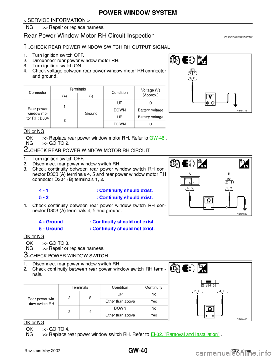
1.CHECK REAR POWER WINDOW SWITCH RH OUTPUT SIGNAL
1. Turn ignition switch OFF.
2. Disconnect rear power window motor RH.
3. Turn ignition switch ON.
4. Check voltage between rear power window motor RH connector
and ground.
OK or NG
OK >> Replace rear power window motor RH. Refer to GW-46 .
NG >> GO TO 2.
2.CHECK REAR POWER WINDOW MOTOR RH CIRCUIT
1. Turn ignition switch OFF.
2. Disconnect rear power window switch RH.
3. Check continuity between rear power window switch RH con-
nector D303 (A) terminals 4, 5 and rear power window motor RH
connector D304 (B) terminals 1, 2.
4. Check continuity between rear power window switch RH con-
nector D303 (A) terminals 4, 5 and ground.
OK or NG
OK >> GO TO 3.
NG >> Repair or replace harness.
3.CHECK POWER WINDOW SWITCH
1. Disconnect rear power window switch RH.
2. Check continuity between rear power window switch RH termi-
nals.
OK or NG
OK >> GO TO 4.
NG >> Replace rear power window switch RH. Refer to EI-32, "
Removal and Installation" .
ConnectorTe r m i n a l s
ConditionVoltage (V)
(Approx.)
(+) (-)
Rear power
window mo-
tor RH: D3041
GroundUP 0
DOWN Battery voltage
2UP Battery voltage
DOWN 0
PIIB6431E
4 - 1 : Continuity should exist.
5 - 2 : Continuity should exist.
4 - Ground : Continuity should not exist.
5 - Ground : Continuity should not exist.
PIIB6432E
Rear power win-
dow switch RHTerminals Condition Continuity
25UP No
Other than above Yes
34DOWN No
Other than above Yes
PIIB6448E
Page 1943 of 2771
GW-42
< SERVICE INFORMATION >
FRONT DOOR GLASS AND REGULATOR
FRONT DOOR GLASS AND REGULATOR
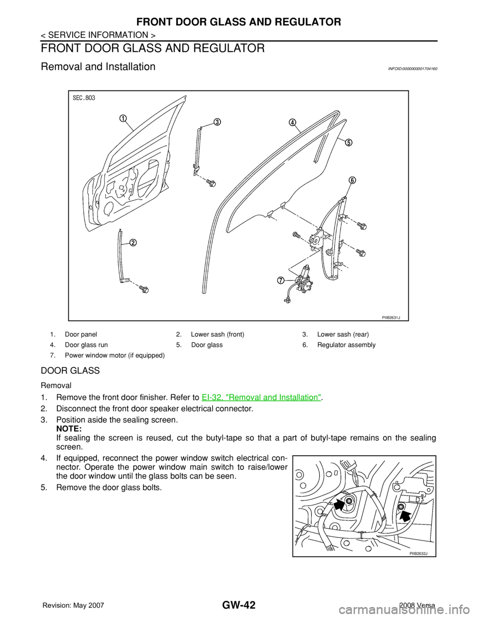
Removal and InstallationINFOID:0000000001704160
DOOR GLASS
Removal
1. Remove the front door finisher. Refer to EI-32, "Removal and Installation".
2. Disconnect the front door speaker electrical connector.
3. Position aside the sealing screen.
NOTE:
If sealing the screen is reused, cut the butyl-tape so that a part of butyl-tape remains on the sealing
screen.
4. If equipped, reconnect the power window switch electrical con-
nector. Operate the power window main switch to raise/lower
the door window until the glass bolts can be seen.
5. Remove the door glass bolts.
1. Door panel 2. Lower sash (front) 3. Lower sash (rear)
4. Door glass run 5. Door glass 6. Regulator assembly
7. Power window motor (if equipped)
PIIB2631J
PIIB2632J
Page 1945 of 2771
GW-44
< SERVICE INFORMATION >
FRONT DOOR GLASS AND REGULATOR
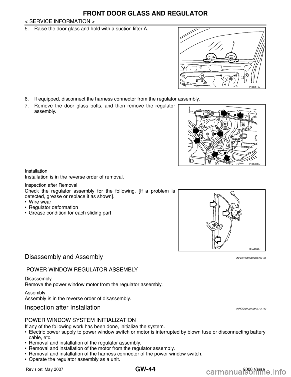
5. Raise the door glass and hold with a suction lifter A.
6. If equipped, disconnect the harness connector from the regulator assembly.
7. Remove the door glass bolts, and then remove the regulator
assembly.
Installation
Installation is in the reverse order of removal.
Inspection after Removal
Check the regulator assembly for the following. [If a problem is
detected, grease or replace it as shown].
• Wire wear
• Regulator deformation
• Grease condition for each sliding part
Disassembly and AssemblyINFOID:0000000001704161
POWER WINDOW REGULATOR ASSEMBLY
Disassembly
Remove the power window motor from the regulator assembly.
Assembly
Assembly is in the reverse order of disassembly.
Inspection after InstallationINFOID:0000000001704162
POWER WINDOW SYSTEM INITIALIZATION
If any of the following work has been done, initialize the system.
• Electric power supply to power window switch or motor is interrupted by blown fuse or disconnecting battery
cable, etc.
• Removal and installation of the regulator assembly.
• Removal and installation of the motor from the regulator assembly.
• Removal and installation of the harness connector of the power window switch.
• Operate the regulator assembly as a unit.
PIIB3510J
PIIB2633J
SIIA1781J
Page 1947 of 2771
GW-46
< SERVICE INFORMATION >
REAR DOOR GLASS AND REGULATOR
REAR DOOR GLASS AND REGULATOR
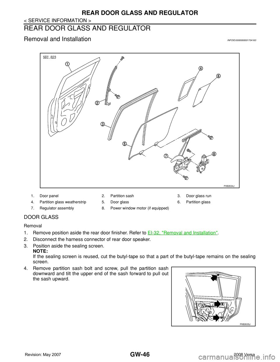
Removal and InstallationINFOID:0000000001704163
DOOR GLASS
Removal
1. Remove position aside the rear door finisher. Refer to EI-32, "Removal and Installation".
2. Disconnect the harness connector of rear door speaker.
3. Position aside the sealing screen.
NOTE:
If the sealing screen is reused, cut the butyl-tape so that a part of the butyl-tape remains on the sealing
screen.
4. Remove partition sash bolt and screw, pull the partition sash
downward and tilt the upper end of the sash forward to pull out
the sash upward.
1. Door panel 2. Partition sash 3. Door glass run
4. Partition glass weatherstrip 5. Door glass 6. Partition glass
7. Regulator assembly 8. Power window motor (if equipped)
PIIB2634J
PIIB2635J
Page 1949 of 2771
GW-48
< SERVICE INFORMATION >
REAR DOOR GLASS AND REGULATOR
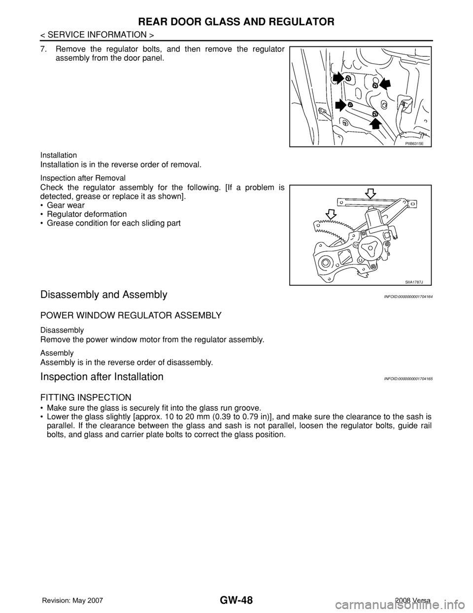
7. Remove the regulator bolts, and then remove the regulator
assembly from the door panel.
Installation
Installation is in the reverse order of removal.
Inspection after Removal
Check the regulator assembly for the following. [If a problem is
detected, grease or replace it as shown].
• Gear wear
• Regulator deformation
• Grease condition for each sliding part
Disassembly and AssemblyINFOID:0000000001704164
POWER WINDOW REGULATOR ASSEMBLY
Disassembly
Remove the power window motor from the regulator assembly.
Assembly
Assembly is in the reverse order of disassembly.
Inspection after InstallationINFOID:0000000001704165
FITTING INSPECTION
• Make sure the glass is securely fit into the glass run groove.
• Lower the glass slightly [approx. 10 to 20 mm (0.39 to 0.79 in)], and make sure the clearance to the sash is
parallel. If the clearance between the glass and sash is not parallel, loosen the regulator bolts, guide rail
bolts, and glass and carrier plate bolts to correct the glass position.
PIIB6315E
SIIA1787J