2008 NISSAN TIIDA transmission oil
[x] Cancel search: transmission oilPage 854 of 2771
CVT FLUID
CVT-15
< SERVICE INFORMATION >
D
E
F
G
H
I
J
K
L
MA
B
CVT
N
O
P
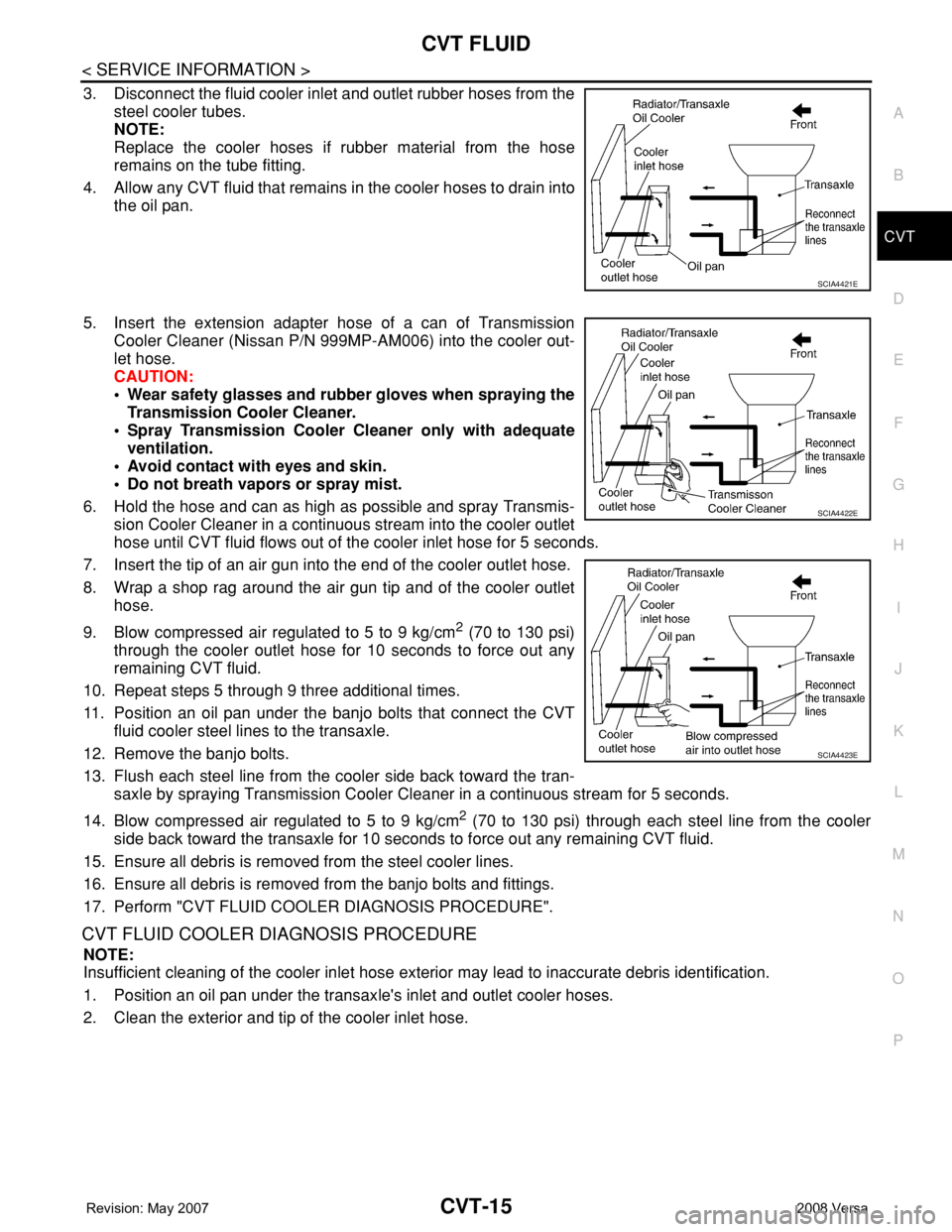
3. Disconnect the fluid cooler inlet and outlet rubber hoses from the
steel cooler tubes.
NOTE:
Replace the cooler hoses if rubber material from the hose
remains on the tube fitting.
4. Allow any CVT fluid that remains in the cooler hoses to drain into
the oil pan.
5. Insert the extension adapter hose of a can of Transmission
Cooler Cleaner (Nissan P/N 999MP-AM006) into the cooler out-
let hose.
CAUTION:
• Wear safety glasses and rubber gloves when spraying the
Transmission Cooler Cleaner.
• Spray Transmission Cooler Cleaner only with adequate
ventilation.
• Avoid contact with eyes and skin.
• Do not breath vapors or spray mist.
6. Hold the hose and can as high as possible and spray Transmis-
sion Cooler Cleaner in a continuous stream into the cooler outlet
hose until CVT fluid flows out of the cooler inlet hose for 5 seconds.
7. Insert the tip of an air gun into the end of the cooler outlet hose.
8. Wrap a shop rag around the air gun tip and of the cooler outlet
hose.
9. Blow compressed air regulated to 5 to 9 kg/cm
2 (70 to 130 psi)
through the cooler outlet hose for 10 seconds to force out any
remaining CVT fluid.
10. Repeat steps 5 through 9 three additional times.
11. Position an oil pan under the banjo bolts that connect the CVT
fluid cooler steel lines to the transaxle.
12. Remove the banjo bolts.
13. Flush each steel line from the cooler side back toward the tran-
saxle by spraying Transmission Cooler Cleaner in a continuous stream for 5 seconds.
14. Blow compressed air regulated to 5 to 9 kg/cm
2 (70 to 130 psi) through each steel line from the cooler
side back toward the transaxle for 10 seconds to force out any remaining CVT fluid.
15. Ensure all debris is removed from the steel cooler lines.
16. Ensure all debris is removed from the banjo bolts and fittings.
17. Perform "CVT FLUID COOLER DIAGNOSIS PROCEDURE".
CVT FLUID COOLER DIAGNOSIS PROCEDURE
NOTE:
Insufficient cleaning of the cooler inlet hose exterior may lead to inaccurate debris identification.
1. Position an oil pan under the transaxle's inlet and outlet cooler hoses.
2. Clean the exterior and tip of the cooler inlet hose.
SCIA4421E
SCIA4422E
SCIA4423E
Page 868 of 2771
TROUBLE DIAGNOSIS
CVT-29
< SERVICE INFORMATION >
D
E
F
G
H
I
J
K
L
MA
B
CVT
N
O
P
TROUBLE DIAGNOSIS
DTC Inspection Priority ChartINFOID:0000000001703451
If some DTCs are displayed at the same time, perform inspections one by one based on the following priority
chart.
NOTE:
If DTC “U1000 CAN COMM CIRCUIT” is displayed with other DTCs, first perform the trouble diagnosis
for “DTC U1000 CAN COMMUNICATION LINE”. Refer to CVT-56
.
Fail-SafeINFOID:0000000001703452
The TCM has an electrical fail-safe mode. This mode makes it possible to operate even if there is an error in a
main electronic control input/output signal circuit.
FAIL-SAFE FUNCTION
If any malfunction occurs in a sensor or solenoid, this function controls the CVT to make driving possible.
Output Speed Sensor (Secondary Speed Sensor)
The shift pattern is changed in accordance with throttle position when an unexpected signal is sent from the
output speed sensor (secondary speed sensor) to the TCM. The overdrive-off mode is inhibited, and the tran-
saxle is put in “D”.
Input Speed Sensor (Primary Speed Sensor)
The shift pattern is changed in accordance with throttle position and secondary speed (vehicle speed) when
an unexpected signal is sent from the input speed sensor (primary speed sensor) to the TCM. The sport mode
is inhibited, and the transaxle is put in “D”.
PNP Switch
If an unexpected signal is sent from the PNP switch to the TCM, the transaxle is put in “D”.
CVT Fluid Temperature Sensor
If an unexpected signal is sent from the CVT fluid temperature sensor to the TCM, the gear ratio in use before
receiving the unexpected signal is maintained or the gear ratio is controlled to keep engine speed under 3500
rpm.
Transmission Fluid Pressure Sensor A (Secondary Pressure Sensor)
• If an unexpected signal is sent from the transmission fluid pressure sensor A (secondary pressure sensor) to
the TCM, the secondary pressure feedback control is stopped and the offset value obtained before the non-
standard condition occurs is used to control line pressure.
• If transmission fluid pressure sensor A (secondary pressure sensor) error signal is input to TCM, secondary
pressure feedback control stops, but line pressure is controlled normally.
Pressure Control Solenoid A (Line Pressure Solenoid)
If an unexpected signal is sent from the solenoid to the TCM, the pressure control solenoid A (line pressure
solenoid) is turned OFF to achieve the maximum fluid pressure.
Pressure Control Solenoid B (Secondary Pressure Solenoid)
If an unexpected signal is sent from the solenoid to the TCM, the pressure control solenoid B (secondary pres-
sure solenoid) is turned OFF to achieve the maximum fluid pressure.
Torque Converter Clutch Solenoid
If an unexpected signal is sent from the solenoid to the TCM, the torque converter clutch solenoid is turned
OFF to cancel the lock-up.
Ste p M oto r
If an unexpected signal is sent from the step motor to the TCM, the step motor coil phases “A” through “D” are
all turned OFF to hold the gear ratio used right before the non-standard condition occurred.
CVT Lock-up Select Solenoid
Priority Detected items (DTC)
1 U1000 CAN communication line
2 Except above
Page 934 of 2771
DTC P0745 LINE PRESSURE SOLENOID VALVE
CVT-95
< SERVICE INFORMATION >
D
E
F
G
H
I
J
K
L
MA
B
CVT
N
O
P
DTC P0745 LINE PRESSURE SOLENOID VALVE
DescriptionINFOID:0000000001703545
• The pressure control solenoid valve A (line pressure solenoid valve) is included in the control valve assem-
bly.
• The pressure control solenoid valve A (line pressure solenoid valve) regulates the oil pump discharge pres-
sure to suit the driving condition in response to a signal sent from the TCM.
CONSULT-III Reference Value in Data Monitor ModeINFOID:0000000001703546
Remarks: Specification data are reference values.
On Board Diagnosis LogicINFOID:0000000001703547
• This is an OBD-II self-diagnostic item.
• Diagnostic trouble code “P0745 L/PRESS SOL/CIRC” with CONSULT-III is detected under the following
conditions.
- TCM detects an improper voltage drop when it tries to operate the solenoid valve.
- When TCM compares target value with monitor value and detects an irregularity.
Possible CauseINFOID:0000000001703548
• Harness or connectors
(Solenoid circuit is open or shorted.)
• Pressure control solenoid valve A (Line pressure solenoid valve)
DTC Confirmation ProcedureINFOID:0000000001703549
NOTE:
If “DTC Confirmation Procedure” has been previously performed, always turn ignition switch OFF and
wait at least 10 seconds before performing the next test.
After the repair, perform the following procedure to confirm the malfunction is eliminated.
WITH CONSULT-III
1. Turn ignition switch ON and select “DATA MONITOR” mode for “TRANSMISSION” with CONSULT-III.
2. Start engine and wait at least 5 seconds.
3. If DTC is detected, go to CVT-97, "
Diagnosis Procedure".
WITH GST
Follow the procedure “WITH CONSULT-III”.
Item name Condition Display value (Approx.)
ISOLT2Release your foot from the accelerator pedal. 0.8 A
Press the accelerator pedal all the way down. 0.0 A
Page 939 of 2771

CVT-100
< SERVICE INFORMATION >
DTC P0746 PRESSURE CONTROL SOLENOID A PERFORMANCE (LINE PRES-
SURE SOLENOID VALVE)
DTC P0746 PRESSURE CONTROL SOLENOID A PERFORMANCE (LINE
PRESSURE SOLENOID VALVE)
DescriptionINFOID:0000000001703553
• The pressure control solenoid valve A (line pressure solenoid valve) is included in the control valve assem-
bly.
• The pressure control solenoid valve A (line pressure solenoid valve) regulates the oil pump discharge pres-
sure to suit the driving condition in response to a signal sent from the TCM.
CONSULT-III Reference Value in Data Monitor ModeINFOID:0000000001703554
Remarks: Specification data are reference values.
On Board Diagnosis LogicINFOID:0000000001703555
• This is an OBD-II self-diagnostic item.
• Diagnostic trouble code “P0746 PRS CNT SOL/A FCTN” with CONSULT-III is detected under the following
conditions.
- Unexpected gear ratio was detected in the LOW side due to excessively low line pressure.
Possible CauseINFOID:0000000001703556
• Line pressure control system
• Output speed sensor (Secondary speed sensor)
• Input speed sensor (Primary speed sensor)
DTC Confirmation ProcedureINFOID:0000000001703557
CAUTION:
Always drive vehicle at a safe speed.
NOTE:
If “DTC Confirmation Procedure” has been previously performed, always turn ignition switch OFF and
wait at least 10 seconds before performing the next test.
After the repair, touch “ERASE” on “SELF-DIAG RESULTS” and then perform the following procedure to con-
firm the malfunction is eliminated.
WITH CONSULT-III
1. Turn ignition switch ON and select “DATA MONITOR” mode for “TRANSMISSION” with CONSULT-III.
2. Start engine and maintain the following conditions for at least 10 consecutive seconds. Test start from 0
km/h (0 MPH).
ATF TEMP SEN: 1.0 - 2.0 V
ACC PEDAL OPEN: More than 1.0/8
RANGE: “D” position
VEHICLE SPEED: 10 km/h (6 MPH) More than
Driving location: Driving the vehicle uphill (increased engine load) will help maintain the driving
conditions required for this test.
3. If DTC is detected, go to CVT-100, "
Diagnosis Procedure".
WITH GST
Follow the procedure “WITH CONSULT-III”.
Diagnosis ProcedureINFOID:0000000001703558
1.CHECK INPUT SIGNAL
With CONSULT-III
1. Start engine.
2. Select “MAIN SIGNALS” in “DATA MONITOR” mode for “TRANSMISSION” with CONSULT-III.
3. Start vehicle and read out the value of “PRI PRESS”.
Item name Condition Display value (Approx.)
PRI PRESS “N” position idle 0.4 MPa
Page 943 of 2771
CVT-104
< SERVICE INFORMATION >
DTC P0778 PRESSURE CONTROL SOLENOID B ELECTRICAL (SEC PRES-
SURE SOLENOID VALVE)
DTC P0778 PRESSURE CONTROL SOLENOID B ELECTRICAL (SEC
PRESSURE SOLENOID VALVE)
DescriptionINFOID:0000000001703565
• The pressure control solenoid valve B (secondary pressure solenoid valve) is included in the control valve
assembly.
• The pressure control solenoid valve B (secondary pressure solenoid valve) regulates the oil pump discharge
pressure to suit the driving condition in response to a signal sent from the TCM.
CONSULT-III Reference Value in Data Monitor ModeINFOID:0000000001703566
Remarks: Specification data are reference values.
On Board Diagnosis LogicINFOID:0000000001703567
• This is an OBD-II self-diagnostic item.
• Diagnostic trouble code “P0778 PRS CNT SOL/B CIRC” with CONSULT-III is detected under the following
conditions.
- TCM detects an improper voltage drop when it tries to operate the solenoid valve.
- When TCM compares target value with monitor value and detects an irregularity.
Possible CauseINFOID:0000000001703568
• Harness or connectors
(Solenoid circuit is open or shorted.)
• Pressure control solenoid valve B (Secondary pressure solenoid valve)
DTC Confirmation ProcedureINFOID:0000000001703569
NOTE:
If “DTC Confirmation Procedure” has been previously performed, always turn ignition switch OFF and
wait at least 10 seconds before performing the next test.
After the repair, perform the following procedure to confirm the malfunction is eliminated.
WITH CONSULT-III
1. Turn ignition switch ON.
2. Select “DATA MONITOR” mode for “TRANSMISSION” with CONSULT-III.
3. Start engine and wait at least 5 seconds.
4. If DTC is detected, go to CVT-106, "
Diagnosis Procedure" .
WITH GST
Follow the procedure “WITH CONSULT-III”.
Item name Condition Display value (Approx.)
ISOLT3 Secondary pressure low - Secondary pressure high 0.8 - 0.0 A
SOLMON3“N” position idle 0.6 - 0.7 A
When stalled 0.4 - 0.6 A
Page 975 of 2771
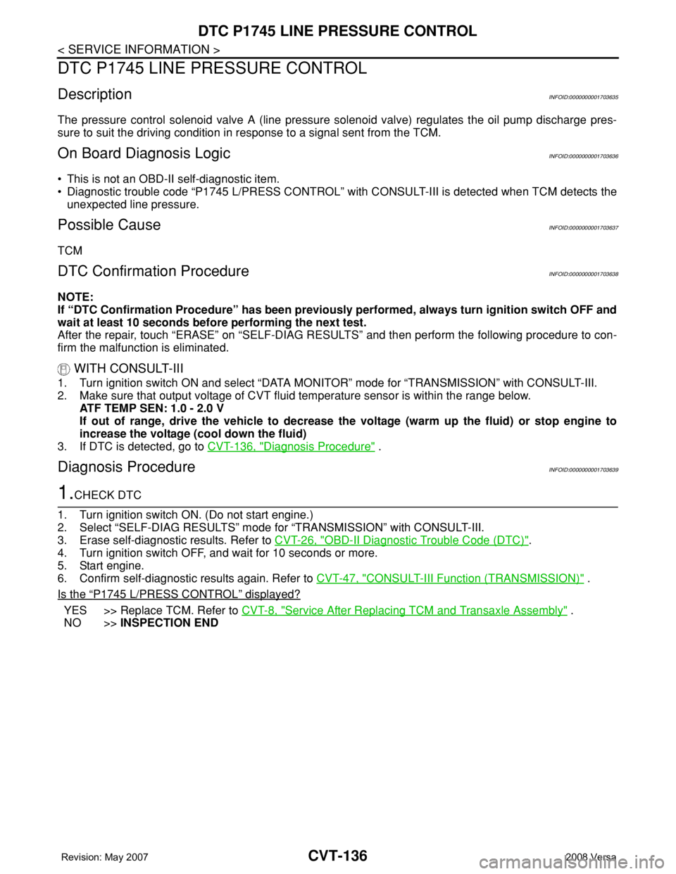
CVT-136
< SERVICE INFORMATION >
DTC P1745 LINE PRESSURE CONTROL
DTC P1745 LINE PRESSURE CONTROL
DescriptionINFOID:0000000001703635
The pressure control solenoid valve A (line pressure solenoid valve) regulates the oil pump discharge pres-
sure to suit the driving condition in response to a signal sent from the TCM.
On Board Diagnosis LogicINFOID:0000000001703636
• This is not an OBD-II self-diagnostic item.
• Diagnostic trouble code “P1745 L/PRESS CONTROL” with CONSULT-III is detected when TCM detects the
unexpected line pressure.
Possible CauseINFOID:0000000001703637
TCM
DTC Confirmation ProcedureINFOID:0000000001703638
NOTE:
If “DTC Confirmation Procedure” has been previously performed, always turn ignition switch OFF and
wait at least 10 seconds before performing the next test.
After the repair, touch “ERASE” on “SELF-DIAG RESULTS” and then perform the following procedure to con-
firm the malfunction is eliminated.
WITH CONSULT-III
1. Turn ignition switch ON and select “DATA MONITOR” mode for “TRANSMISSION” with CONSULT-III.
2. Make sure that output voltage of CVT fluid temperature sensor is within the range below.
ATF TEMP SEN: 1.0 - 2.0 V
If out of range, drive the vehicle to decrease the voltage (warm up the fluid) or stop engine to
increase the voltage (cool down the fluid)
3. If DTC is detected, go to CVT-136, "
Diagnosis Procedure" .
Diagnosis ProcedureINFOID:0000000001703639
1.CHECK DTC
1. Turn ignition switch ON. (Do not start engine.)
2. Select “SELF-DIAG RESULTS” mode for “TRANSMISSION” with CONSULT-III.
3. Erase self-diagnostic results. Refer to CVT-26, "
OBD-II Diagnostic Trouble Code (DTC)".
4. Turn ignition switch OFF, and wait for 10 seconds or more.
5. Start engine.
6. Confirm self-diagnostic results again. Refer to CVT-47, "
CONSULT-III Function (TRANSMISSION)" .
Is the
“P1745 L/PRESS CONTROL” displayed?
YES >> Replace TCM. Refer to CVT-8, "Service After Replacing TCM and Transaxle Assembly" .
NO >>INSPECTION END
Page 976 of 2771
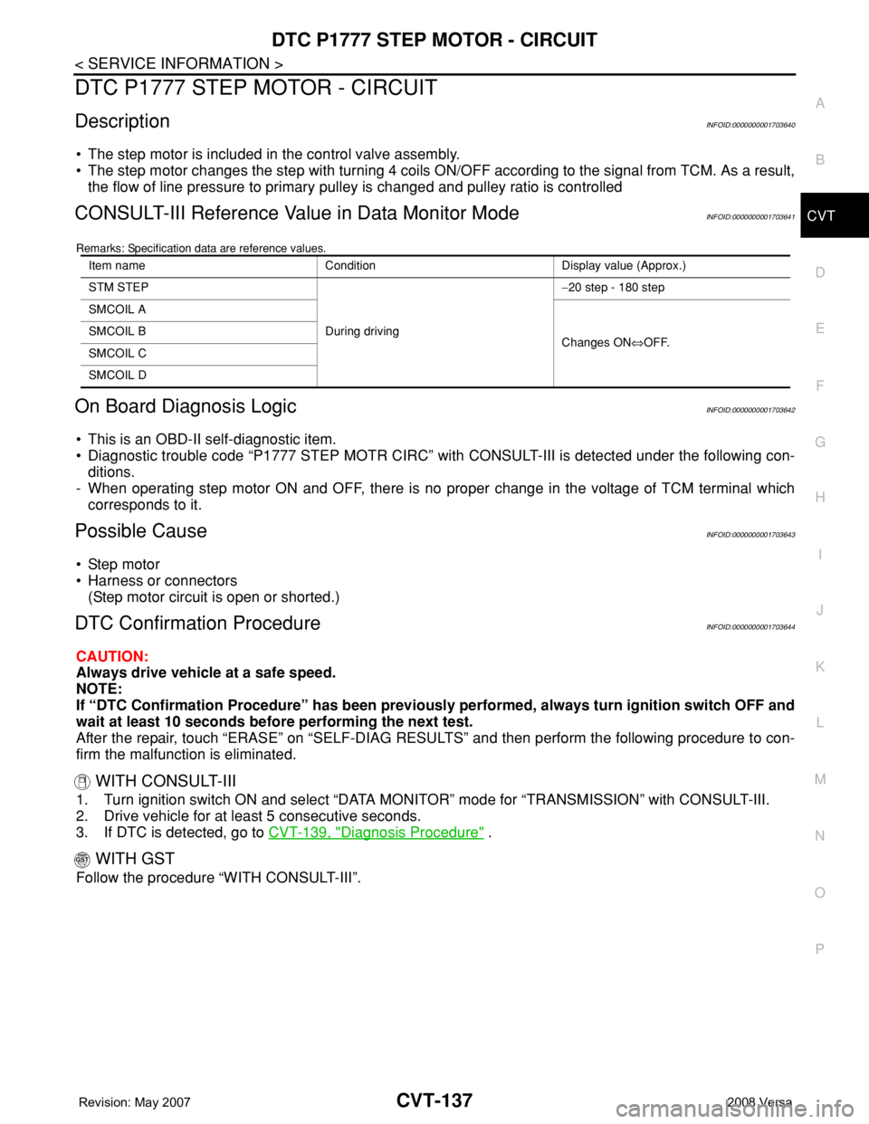
DTC P1777 STEP MOTOR - CIRCUIT
CVT-137
< SERVICE INFORMATION >
D
E
F
G
H
I
J
K
L
MA
B
CVT
N
O
P
DTC P1777 STEP MOTOR - CIRCUIT
DescriptionINFOID:0000000001703640
• The step motor is included in the control valve assembly.
• The step motor changes the step with turning 4 coils ON/OFF according to the signal from TCM. As a result,
the flow of line pressure to primary pulley is changed and pulley ratio is controlled
CONSULT-III Reference Value in Data Monitor ModeINFOID:0000000001703641
Remarks: Specification data are reference values.
On Board Diagnosis LogicINFOID:0000000001703642
• This is an OBD-II self-diagnostic item.
• Diagnostic trouble code “P1777 STEP MOTR CIRC” with CONSULT-III is detected under the following con-
ditions.
- When operating step motor ON and OFF, there is no proper change in the voltage of TCM terminal which
corresponds to it.
Possible CauseINFOID:0000000001703643
• Step motor
• Harness or connectors
(Step motor circuit is open or shorted.)
DTC Confirmation ProcedureINFOID:0000000001703644
CAUTION:
Always drive vehicle at a safe speed.
NOTE:
If “DTC Confirmation Procedure” has been previously performed, always turn ignition switch OFF and
wait at least 10 seconds before performing the next test.
After the repair, touch “ERASE” on “SELF-DIAG RESULTS” and then perform the following procedure to con-
firm the malfunction is eliminated.
WITH CONSULT-III
1. Turn ignition switch ON and select “DATA MONITOR” mode for “TRANSMISSION” with CONSULT-III.
2. Drive vehicle for at least 5 consecutive seconds.
3. If DTC is detected, go to CVT-139, "
Diagnosis Procedure" .
WITH GST
Follow the procedure “WITH CONSULT-III”.
Item name Condition Display value (Approx.)
STM STEP
During driving−20 step - 180 step
SMCOIL A
Changes ON⇔OFF. SMCOIL B
SMCOIL C
SMCOIL D
Page 978 of 2771
DTC P1777 STEP MOTOR - CIRCUIT
CVT-139
< SERVICE INFORMATION >
D
E
F
G
H
I
J
K
L
MA
B
CVT
N
O
P
Diagnosis ProcedureINFOID:0000000001703646
1.CHECK INPUT SIGNALS
With CONSULT-III
1. Start engine.
2. Select “SELECTION FROM MENU” in “DATA MONITOR” mode for “TRANSMISSION” with CONSULT-III.
3. Start vehicle and read out the value of “STM STEP”, “SMCOIL A”, “SMCOIL B”, “SMCOIL C”, and
“SMCOIL D”.
OK or NG
OK >> GO TO 4.
NG >> GO TO 2.
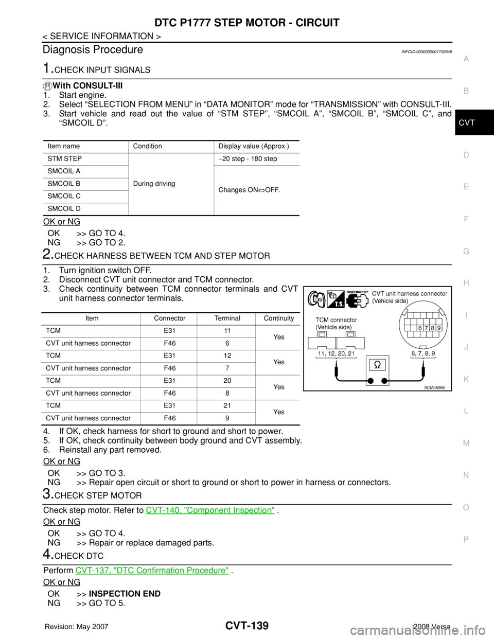
2.CHECK HARNESS BETWEEN TCM AND STEP MOTOR
1. Turn ignition switch OFF.
2. Disconnect CVT unit connector and TCM connector.
3. Check continuity between TCM connector terminals and CVT
unit harness connector terminals.
4. If OK, check harness for short to ground and short to power.
5. If OK, check continuity between body ground and CVT assembly.
6. Reinstall any part removed.
OK or NG
OK >> GO TO 3.
NG >> Repair open circuit or short to ground or short to power in harness or connectors.
3.CHECK STEP MOTOR
Check step motor. Refer to CVT-140, "
Component Inspection" .
OK or NG
OK >> GO TO 4.
NG >> Repair or replace damaged parts.
4.CHECK DTC
Perform CVT-137, "
DTC Confirmation Procedure" .
OK or NG
OK >>INSPECTION END
NG >> GO TO 5.
Item name Condition Display value (Approx.)
STM STEP
During driving−20 step - 180 step
SMCOIL A
Changes ON⇔OFF. SMCOIL B
SMCOIL C
SMCOIL D
Item Connector Terminal Continuity
TCM E31 11
Ye s
CVT unit harness connector F46 6
TCM E31 12
Ye s
CVT unit harness connector F46 7
TCM E31 20
Ye s
CVT unit harness connector F46 8
TCM E31 21
Ye s
CVT unit harness connector F46 9
SCIA4695E