Page 390 of 2771
AUDIO
AV-31
< SERVICE INFORMATION >
C
D
E
F
G
H
I
J
L
MA
B
AV
N
O
P
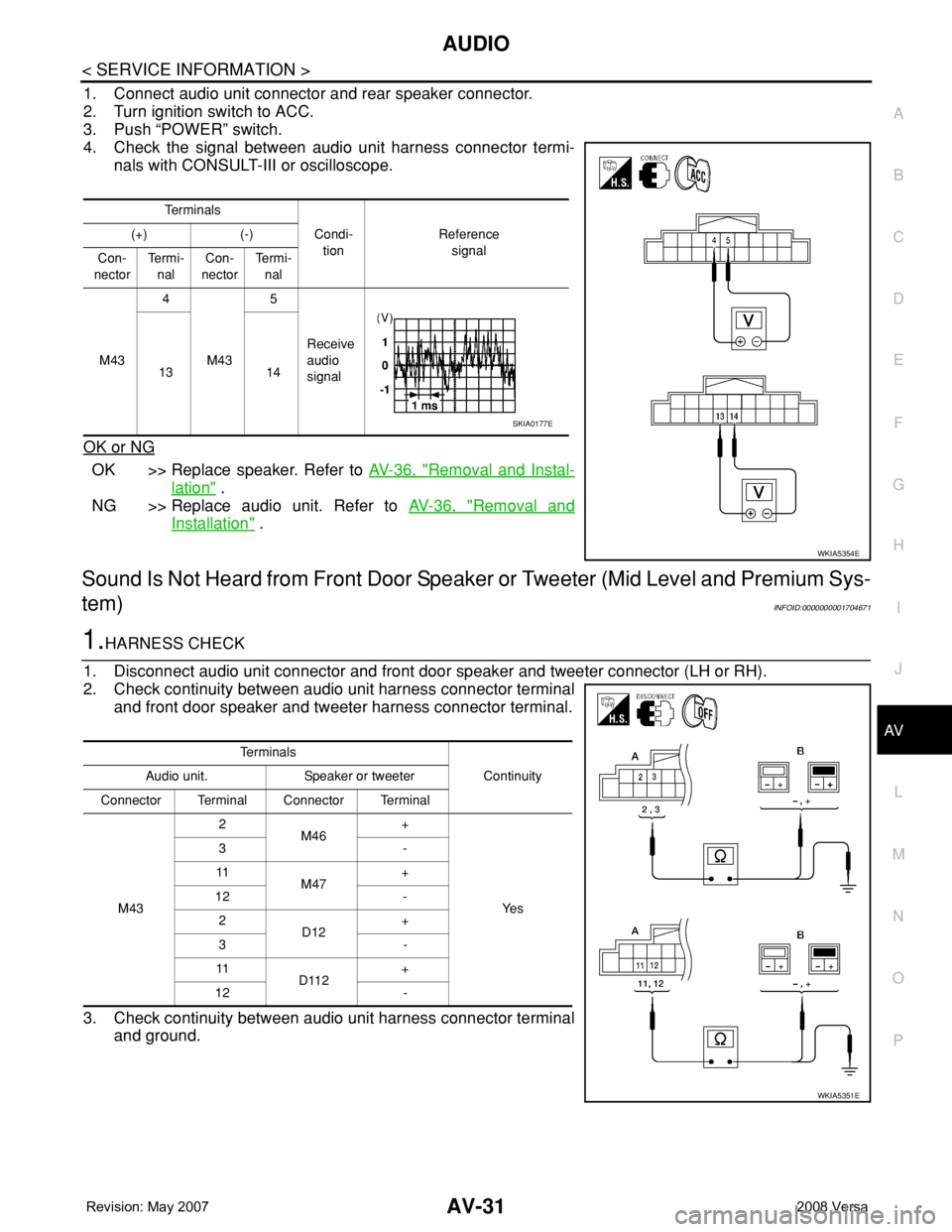
1. Connect audio unit connector and rear speaker connector.
2. Turn ignition switch to ACC.
3. Push “POWER” switch.
4. Check the signal between audio unit harness connector termi-
nals with CONSULT-III or oscilloscope.
OK or NG
OK >> Replace speaker. Refer to AV-36, "Removal and Instal-
lation" .
NG >> Replace audio unit. Refer to AV-36, "
Removal and
Installation" .
Sound Is Not Heard from Front Door Speaker or Tweeter (Mid Level and Premium Sys-
tem)
INFOID:0000000001704671
1.HARNESS CHECK
1. Disconnect audio unit connector and front door speaker and tweeter connector (LH or RH).
2. Check continuity between audio unit harness connector terminal
and front door speaker and tweeter harness connector terminal.
3. Check continuity between audio unit harness connector terminal
and ground.
Te r m i n a l s
Condi-
tionReference
signal (+) (-)
Con-
nectorTe r m i -
nalCon-
nectorTe r m i -
nal
M434
M435
Receive
audio
signal 13 14
WKIA5354E
SKIA0177E
Te r m i n a l s
Continuity Audio unit. Speaker or tweeter
Connector Terminal Connector Terminal
M432
M46+
Ye s 3-
11
M47+
12 -
2
D12+
3-
11
D112+
12 -
WKIA5351E
Page 391 of 2771
AV-32
< SERVICE INFORMATION >
AUDIO
OK or NG
OK >> GO TO 2.
NG >> • Check connector housings for disconnected or loose terminals.
• Repair harness or connector.
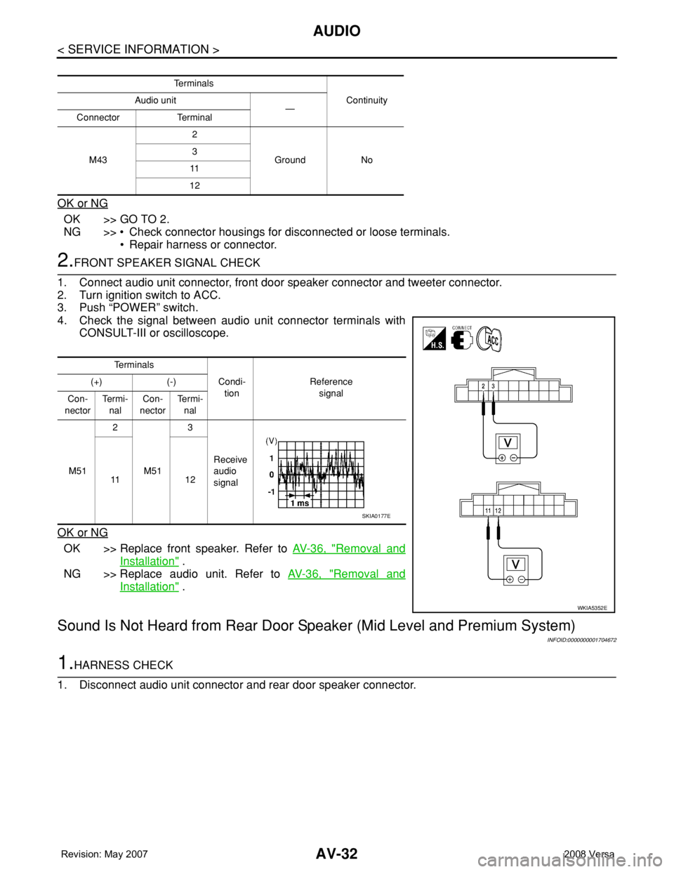
2.FRONT SPEAKER SIGNAL CHECK
1. Connect audio unit connector, front door speaker connector and tweeter connector.
2. Turn ignition switch to ACC.
3. Push “POWER” switch.
4. Check the signal between audio unit connector terminals with
CONSULT-III or oscilloscope.
OK or NG
OK >> Replace front speaker. Refer to AV-36, "Removal and
Installation" .
NG >> Replace audio unit. Refer to AV-36, "
Removal and
Installation" .
Sound Is Not Heard from Rear Door Speaker (Mid Level and Premium System)
INFOID:0000000001704672
1.HARNESS CHECK
1. Disconnect audio unit connector and rear door speaker connector.
Te r m i n a l s
Continuity Audio unit
—
Connector Terminal
M432
Ground No 3
11
12
Te r m i n a l s
Condi-
tionReference
signal (+) (-)
Con-
nectorTe r m i -
nalCon-
nectorTe r m i -
nal
M512
M513
Receive
audio
signal 11 1 2
WKIA5352E
SKIA0177E
Page 392 of 2771
AUDIO
AV-33
< SERVICE INFORMATION >
C
D
E
F
G
H
I
J
L
MA
B
AV
N
O
P
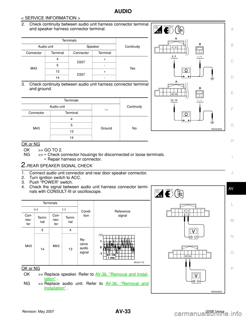
2. Check continuity between audio unit harness connector terminal
and speaker harness connector terminal.
3. Check continuity between audio unit harness connector terminal
and ground.
OK or NG
OK >> GO TO 2.
NG >> • Check connector housings for disconnected or loose terminals.
• Repair harness or connector.
2.REAR SPEAKER SIGNAL CHECK
1. Connect audio unit connector and rear door speaker connector.
2. Turn ignition switch to ACC.
3. Push “POWER” switch.
4. Check the signal between audio unit harness connector termi-
nals with CONSULT-III or oscilloscope.
OK or NG
OK >> Replace speaker. Refer to AV-36, "Removal and Instal-
lation" .
NG >> Replace audio unit. Refer to AV-36, "
Removal and
Installation" .
Te r m i n a l s
Continuity Audio unit Speaker
Connector Terminal Connector Terminal
M434
D207+
Ye s 5-
13
D307+
14 -
Te r m i n a l s
Continuity Audio unit
—
Connector Terminal
M434
Ground No 5
13
14
WKIA5353E
Te r m i n a l s
Condi-
tionReference
signal (+) (-)
Con-
nec-
torTe r m i -
nalCon-
nec-
torTe r m i -
nal
M435
M434
Re-
ceive
audio
signal 14 13
WKIA5354E
SKIA0177E
Page 395 of 2771
AV-36
< SERVICE INFORMATION >
AUDIO
OK or NG
OK >> Replace subwoofer. Refer to AV-36, "Removal and Installation" .
NG >> Replace audio unit. Refer to AV-36, "
Removal and Installation" .
Removal and InstallationINFOID:0000000001704674
AUDIO UNIT
Removal
1. Remove cluster lid C. Refer to IP-10.
2. Remove the audio unit screws (A), disconnect the connectors
and remove the audio unit (1).
3. Remove the audio unit bracket.
Installation
Installation is in the reverse order of removal.
FRONT DOOR SPEAKER
Removal
1. Remove the front door finisher. Refer to EI-32.
2. Remove the front door speaker screws (A), disconnect the con-
nector and remove the front door speaker (1).
Installation
Installation is in the reverse order of removal.
REAR DOOR SPEAKER
Removal
1. Remove the rear door finisher. Refer to EI-32.
2. Remove the rear door finisher screws (A), disconnect the con-
nector and remove the rear door speaker (1).
Installation
SKIB4726E
SKIB4728E
SKIB4729E
Page 403 of 2771
AV-44
< SERVICE INFORMATION >
TELEPHONE
tooth cellular telephones may not be recognized by the Bluetooth control unit. When a cellular telephone or
the Bluetooth control unit is replaced, the telephone must be paired with the Bluetooth control unit. Different
cellular telephones may have different pairing procedures. Refer to the cellular telephone operating manual.
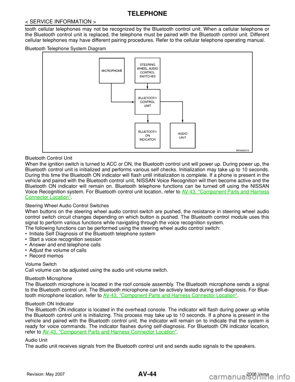
Bluetooth Telephone System Diagram
Bluetooth Control Unit
When the ignition switch is turned to ACC or ON, the Bluetooth control unit will power up. During power up, the
Bluetooth control unit is initialized and performs various self checks. Initialization may take up to 10 seconds.
During this time the Bluetooth ON indicator will flash until initialization is complete. If a phone is present in the
vehicle and paired with the Bluetooth control unit, NISSAN Voice Recognition will then become active and the
Bluetooth ON indicator will remain on. Bluetooth telephone functions can be turned off using the NISSAN
Voice Recognition system. For Bluetooth control unit location, refer to AV-43, "
Component Parts and Harness
Connector Location".
Steering Wheel Audio Control Switches
When buttons on the steering wheel audio control switch are pushed, the resistance in steering wheel audio
control switch circuit changes depending on which button is pushed. The Bluetooth control module uses this
signal to perform various functions while navigating through the voice recognition system.
The following functions can be performed using the steering wheel audio control switch:
• Initiate Self Diagnosis of the Bluetooth telephone system
• Start a voice recognition session
• Answer and end telephone calls
• Adjust the volume of calls
• Record memos
Volume Switch
Call volume can be adjusted using the audio unit volume switch.
Bluetooth Microphone
The Bluetooth microphone is located in the roof console assembly. The Bluetooth microphone sends a signal
to the Bluetooth control unit. The Bluetooth microphone can be actively tested during self-diagnosis. For Blue-
tooth microphone location, refer to AV-43, "
Component Parts and Harness Connector Location".
Bluetooth ON Indicator
The Bluetooth ON indicator is located in the overhead console. The indicator will flash during power up while
the Bluetooth control unit is initializing. This process may take up to 10 seconds. If a phone is present in the
vehicle and paired with the Bluetooth control unit, the indicator will remain on to indicate that the system is
ready for voice commands. The indicator flashes during self-diagnosis. For Bluetooth ON indicator location,
refer to AV-43, "
Component Parts and Harness Connector Location".
Audio Unit
The audio unit receives signals from the Bluetooth control unit and sends audio signals to the speakers.
WKIA6001E
Page 1943 of 2771
GW-42
< SERVICE INFORMATION >
FRONT DOOR GLASS AND REGULATOR
FRONT DOOR GLASS AND REGULATOR
Removal and InstallationINFOID:0000000001704160
DOOR GLASS
Removal
1. Remove the front door finisher. Refer to EI-32, "Removal and Installation".
2. Disconnect the front door speaker electrical connector.
3. Position aside the sealing screen.
NOTE:
If sealing the screen is reused, cut the butyl-tape so that a part of butyl-tape remains on the sealing
screen.
4. If equipped, reconnect the power window switch electrical con-
nector. Operate the power window main switch to raise/lower
the door window until the glass bolts can be seen.
5. Remove the door glass bolts.
1. Door panel 2. Lower sash (front) 3. Lower sash (rear)
4. Door glass run 5. Door glass 6. Regulator assembly
7. Power window motor (if equipped)
PIIB2631J
PIIB2632J
Page 1944 of 2771
FRONT DOOR GLASS AND REGULATOR
GW-43
< SERVICE INFORMATION >
C
D
E
F
G
H
J
K
L
MA
B
GW
N
O
P
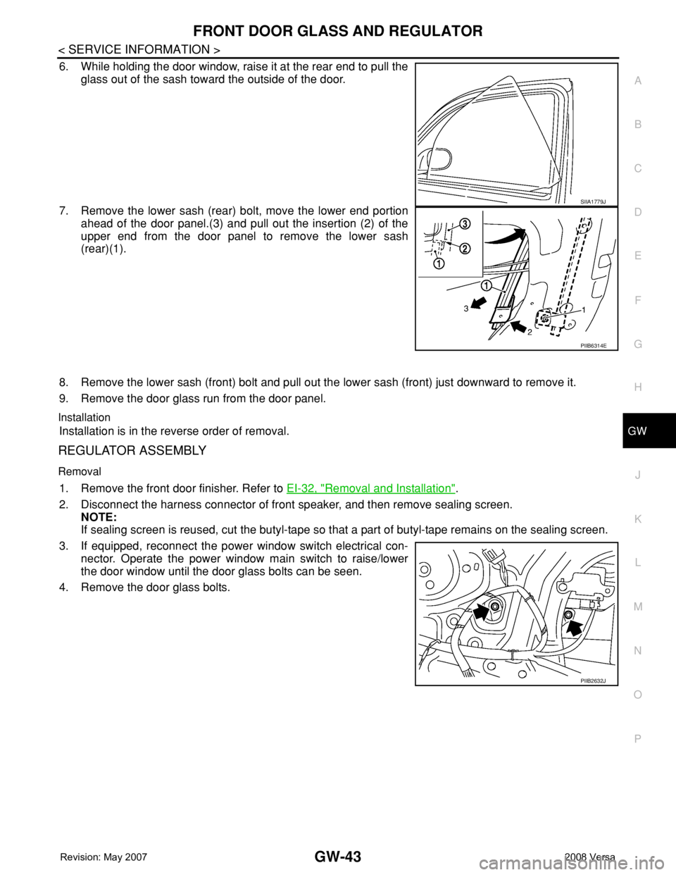
6. While holding the door window, raise it at the rear end to pull the
glass out of the sash toward the outside of the door.
7. Remove the lower sash (rear) bolt, move the lower end portion
ahead of the door panel.(3) and pull out the insertion (2) of the
upper end from the door panel to remove the lower sash
(rear)(1).
8. Remove the lower sash (front) bolt and pull out the lower sash (front) just downward to remove it.
9. Remove the door glass run from the door panel.
Installation
Installation is in the reverse order of removal.
REGULATOR ASSEMBLY
Removal
1. Remove the front door finisher. Refer to EI-32, "Removal and Installation".
2. Disconnect the harness connector of front speaker, and then remove sealing screen.
NOTE:
If sealing screen is reused, cut the butyl-tape so that a part of butyl-tape remains on the sealing screen.
3. If equipped, reconnect the power window switch electrical con-
nector. Operate the power window main switch to raise/lower
the door window until the door glass bolts can be seen.
4. Remove the door glass bolts.
SIIA1779J
PIIB6314E
PIIB2632J
Page 1947 of 2771
GW-46
< SERVICE INFORMATION >
REAR DOOR GLASS AND REGULATOR
REAR DOOR GLASS AND REGULATOR
Removal and InstallationINFOID:0000000001704163
DOOR GLASS
Removal
1. Remove position aside the rear door finisher. Refer to EI-32, "Removal and Installation".
2. Disconnect the harness connector of rear door speaker.
3. Position aside the sealing screen.
NOTE:
If the sealing screen is reused, cut the butyl-tape so that a part of the butyl-tape remains on the sealing
screen.
4. Remove partition sash bolt and screw, pull the partition sash
downward and tilt the upper end of the sash forward to pull out
the sash upward.
1. Door panel 2. Partition sash 3. Door glass run
4. Partition glass weatherstrip 5. Door glass 6. Partition glass
7. Regulator assembly 8. Power window motor (if equipped)
PIIB2634J
PIIB2635J