2008 NISSAN TIIDA connector d2
[x] Cancel search: connector d2Page 2140 of 2771
PRECAUTIONS
LT-3
< SERVICE INFORMATION >
C
D
E
F
G
H
I
J
L
MA
B
LT
N
O
P
SERVICE INFORMATION
PRECAUTIONS
Precaution for Supplemental Restraint System (SRS) "AIR BAG" and "SEAT BELT
PRE-TENSIONER"
INFOID:0000000001704359
The Supplemental Restraint System such as “AIR BAG” and “SEAT BELT PRE-TENSIONER”, used along
with a front seat belt, helps to reduce the risk or severity of injury to the driver and front passenger for certain
types of collision. This system includes seat belt switch inputs and dual stage front air bag modules. The SRS
system uses the seat belt switches to determine the front air bag deployment, and may only deploy one front
air bag, depending on the severity of a collision and whether the front occupants are belted or unbelted.
Information necessary to service the system safely is included in the SRS and SB section of this Service Man-
ual.
WARNING:
• To avoid rendering the SRS inoperative, which could increase the risk of personal injury or death in
the event of a collision which would result in air bag inflation, all maintenance must be performed by
an authorized NISSAN/INFINITI dealer.
• Improper maintenance, including incorrect removal and installation of the SRS, can lead to personal
injury caused by unintentional activation of the system. For removal of Spiral Cable and Air Bag
Module, see the SRS section.
• Do not use electrical test equipment on any circuit related to the SRS unless instructed to in this
Service Manual. SRS wiring harnesses can be identified by yellow and/or orange harnesses or har-
ness connectors.
Page 2141 of 2771
LT-4
< SERVICE INFORMATION >
HEADLAMP (FOR USA)
HEADLAMP (FOR USA)
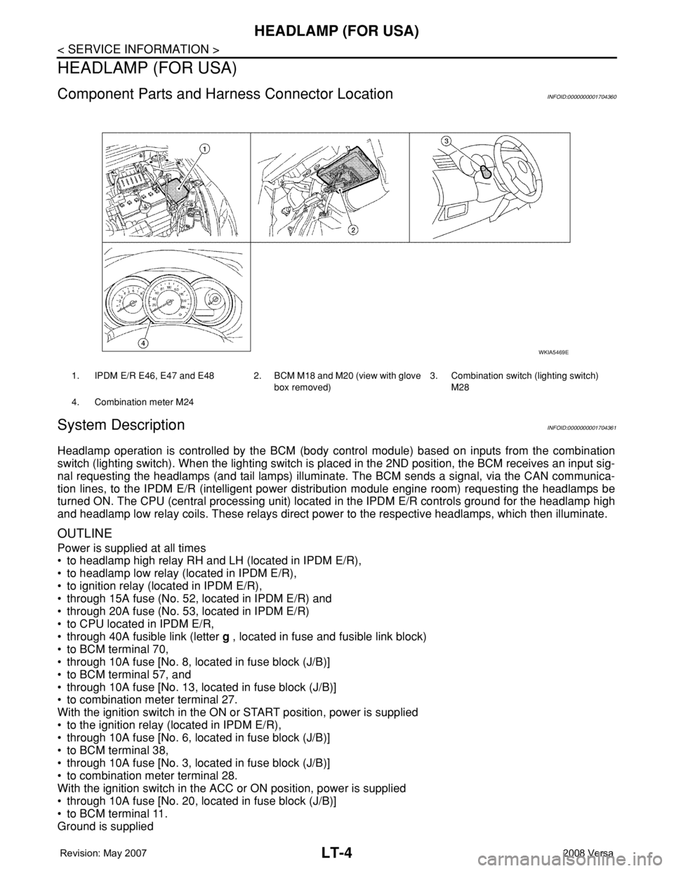
Component Parts and Harness Connector LocationINFOID:0000000001704360
System DescriptionINFOID:0000000001704361
Headlamp operation is controlled by the BCM (body control module) based on inputs from the combination
switch (lighting switch). When the lighting switch is placed in the 2ND position, the BCM receives an input sig-
nal requesting the headlamps (and tail lamps) illuminate. The BCM sends a signal, via the CAN communica-
tion lines, to the IPDM E/R (intelligent power distribution module engine room) requesting the headlamps be
turned ON. The CPU (central processing unit) located in the IPDM E/R controls ground for the headlamp high
and headlamp low relay coils. These relays direct power to the respective headlamps, which then illuminate.
OUTLINE
Power is supplied at all times
• to headlamp high relay RH and LH (located in IPDM E/R),
• to headlamp low relay (located in IPDM E/R),
• to ignition relay (located in IPDM E/R),
• through 15A fuse (No. 52, located in IPDM E/R) and
• through 20A fuse (No. 53, located in IPDM E/R)
• to CPU located in IPDM E/R,
• through 40A fusible link (letter g , located in fuse and fusible link block)
• to BCM terminal 70,
• through 10A fuse [No. 8, located in fuse block (J/B)]
• to BCM terminal 57, and
• through 10A fuse [No. 13, located in fuse block (J/B)]
• to combination meter terminal 27.
With the ignition switch in the ON or START position, power is supplied
• to the ignition relay (located in IPDM E/R),
• through 10A fuse [No. 6, located in fuse block (J/B)]
• to BCM terminal 38,
• through 10A fuse [No. 3, located in fuse block (J/B)]
• to combination meter terminal 28.
With the ignition switch in the ACC or ON position, power is supplied
• through 10A fuse [No. 20, located in fuse block (J/B)]
• to BCM terminal 11.
Ground is supplied
1. IPDM E/R E46, E47 and E48 2. BCM M18 and M20 (view with glove
box removed)3. Combination switch (lighting switch)
M28
4. Combination meter M24
WKIA5469E
Page 2151 of 2771
LT-14
< SERVICE INFORMATION >
HEADLAMP (FOR USA)
OK or NG
OK >> GO TO 3.
NG >> GO TO 4.
3.CHECK IPDM E/R
1. Select “IPDM E/R” on CONSULT-III. Select “DATA MONITOR” on “SELECT DIAG MODE” screen.
2. Make sure “HL HI REQ” turns ON when lighting switch is in high position.
OK or NG
OK >> Replace IPDM E/R. Refer to PG-26, "Removal and Installation of IPDM E/R" .
NG >> Replace BCM. Refer to BCS-18, "
Removal and Installation of BCM" .
4.HEADLAMP HIGH BEAM FUSE INSPECTION
Inspect 10A fuse No. 34 (LH) and fuse No. 35 (RH).
OK or NG
OK >> GO TO 5.
NG >> Repair harness.
5.BULB INSPECTION
Inspect inoperative headlamp bulbs.
OK or NG
OK >> GO TO 6.
NG >> Replace headlamp bulb. LT-22, "
Bulb Replacement" .
6.CHECK HEADLAMP INPUT SIGNAL
With CONSULT-III
1. Turn ignition switch OFF.
2. Disconnect headlamp connector.
3. Select “IPDM E/R” on CONSULT-III. Select “ACTIVE TEST” on “SELECT DIAG MODE” screen.
4. Select “EXTERNAL LAMPS” on “SELECT TEST ITEM” screen.
5. Touch “HI” screen.
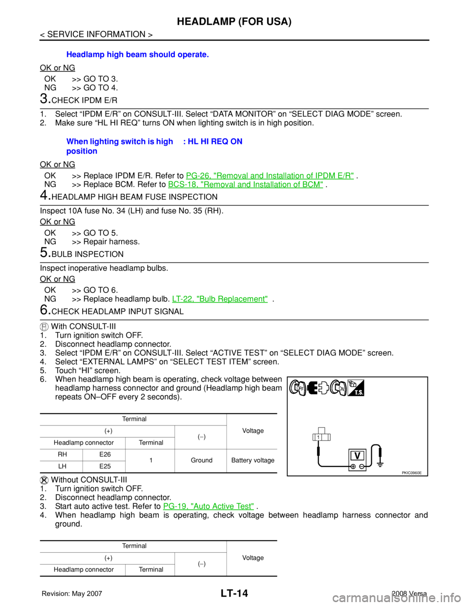
6. When headlamp high beam is operating, check voltage between
headlamp harness connector and ground (Headlamp high beam
repeats ON–OFF every 2 seconds).
Without CONSULT-III
1. Turn ignition switch OFF.
2. Disconnect headlamp connector.
3. Start auto active test. Refer to PG-19, "
Auto Active Test" .
4. When headlamp high beam is operating, check voltage between headlamp harness connector and
ground.Headlamp high beam should operate.
When lighting switch is high
position: HL HI REQ ON
Te r m i n a l
Vo l ta g e (+)
(−)
Headlamp connector Terminal
RH E26
1 Ground Battery voltage
LH E25
Te r m i n a l
Vo l ta g e (+)
(−)
Headlamp connector Terminal
PKIC0960E
Page 2152 of 2771
HEADLAMP (FOR USA)
LT-15
< SERVICE INFORMATION >
C
D
E
F
G
H
I
J
L
MA
B
LT
N
O
P
OK or NG
OK >> GO TO 7.
NG >> GO TO 8.
7.CHECK HEADLAMP GROUND CIRCUIT
1. Turn ignition switch OFF.
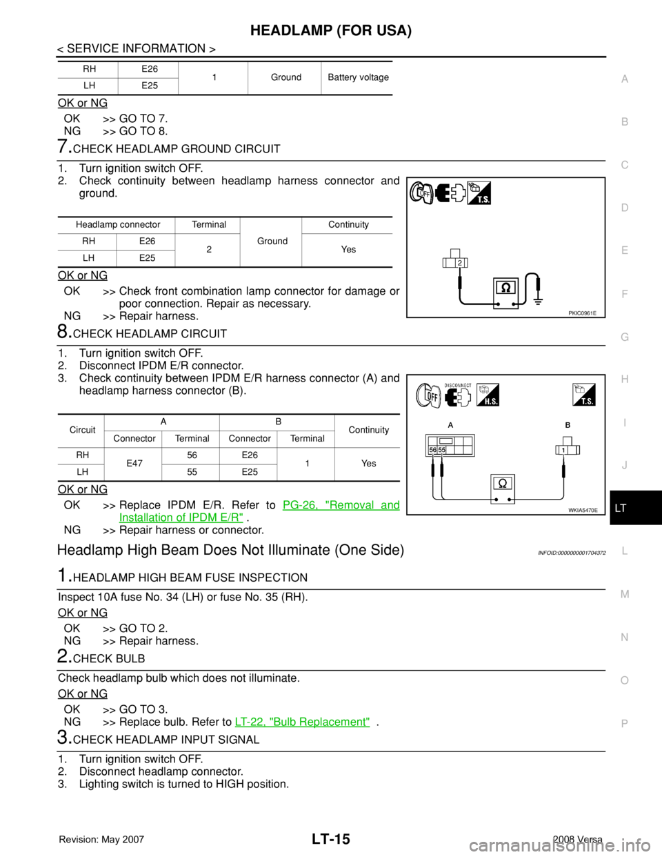
2. Check continuity between headlamp harness connector and
ground.
OK or NG
OK >> Check front combination lamp connector for damage or
poor connection. Repair as necessary.
NG >> Repair harness.
8.CHECK HEADLAMP CIRCUIT
1. Turn ignition switch OFF.
2. Disconnect IPDM E/R connector.
3. Check continuity between IPDM E/R harness connector (A) and
headlamp harness connector (B).
OK or NG
OK >> Replace IPDM E/R. Refer to PG-26, "Removal and
Installation of IPDM E/R" .
NG >> Repair harness or connector.
Headlamp High Beam Does Not Illuminate (One Side)INFOID:0000000001704372
1.HEADLAMP HIGH BEAM FUSE INSPECTION
Inspect 10A fuse No. 34 (LH) or fuse No. 35 (RH).
OK or NG
OK >> GO TO 2.
NG >> Repair harness.
2.CHECK BULB
Check headlamp bulb which does not illuminate.
OK or NG
OK >> GO TO 3.
NG >> Replace bulb. Refer to LT-22, "
Bulb Replacement" .
3.CHECK HEADLAMP INPUT SIGNAL
1. Turn ignition switch OFF.
2. Disconnect headlamp connector.
3. Lighting switch is turned to HIGH position.
RH E26
1 Ground Battery voltage
LH E25
Headlamp connector Terminal
Ground Continuity
RH E26
2Yes
LH E25
PKIC0961E
CircuitAB
Continuity
Connector Terminal Connector Terminal
RH
E4756 E26
1 Yes
LH 55 E25
WKIA5470E
Page 2153 of 2771
LT-16
< SERVICE INFORMATION >
HEADLAMP (FOR USA)
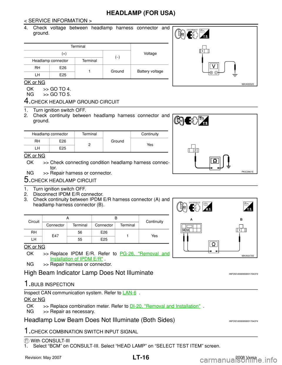
4. Check voltage between headlamp harness connector and
ground.
OK or NG
OK >> GO TO 4.
NG >> GO TO 5.
4.CHECK HEADLAMP GROUND CIRCUIT
1. Turn ignition switch OFF.
2. Check continuity between headlamp harness connector and
ground.
OK or NG
OK >> Check connecting condition headlamp harness connec-
tor.
NG >> Repair harness or connector.
5.CHECK HEADLAMP CIRCUIT
1. Turn ignition switch OFF.
2. Disconnect IPDM E/R connector.
3. Check continuity between IPDM E/R harness connector (A) and
headlamp harness connector (B).
OK or NG
OK >> Replace IPDM E/R. Refer to PG-26, "Removal and
Installation of IPDM E/R" .
NG >> Repair harness or connector.
High Beam Indicator Lamp Does Not IlluminateINFOID:0000000001704373
1.BULB INSPECTION
Inspect CAN communication system. Refer to LAN-6
.
OK or NG
OK >> Replace combination meter. Refer to DI-20, "Removal and Installation" .
NG >> Repair as necessary.
Headlamp Low Beam Does Not Illuminate (Both Sides)INFOID:0000000001704374
1.CHECK COMBINATION SWITCH INPUT SIGNAL
With CONSULT-III
1. Select “BCM” on CONSULT-III. Select “HEAD LAMP” on “SELECT TEST ITEM” screen.
Te r m i n a l
Voltag e (+)
(−)
Headlamp connector Terminal
RH E26
1 Ground Battery voltage
LH E25
WKIA5552E
Headlamp connector Terminal
Ground Continuity
RH E26
2Yes
LH E25
PKIC0961E
CircuitAB
Continuity
Connector Terminal Connector Terminal
RH
E47 56 E26
1Yes
LH 55 E25
WKIA5470E
Page 2154 of 2771
HEADLAMP (FOR USA)
LT-17
< SERVICE INFORMATION >
C
D
E
F
G
H
I
J
L
MA
B
LT
N
O
P
2. Select “DATA MONITOR” on “SELECT DIAG MODE” screen. Make sure that “HEAD LAMP SW 1” and
“HEAD LAMP SW 2” turns ON-OFF linked with operation of lighting switch.
Without CONSULT-III
Refer to LT-63, "
Combination Switch Inspection" .
OK or NG
OK >> GO TO 2.
NG >> Check combination switch (lighting switch). Refer to LT-63, "
Combination Switch Inspection" .
2.CHECK HEADLAMP ACTIVE TEST
With CONSULT-III
1. Select “IPDM E/R” on CONSULT-III. Select “ACTIVE TEST” on “SELECT DIAG MODE” screen.
2. Select “EXTERNAL LAMPS” on “SELECT TEST ITEM” screen.
3. Touch “LO” screen.
4. Make sure headlamp low beam operates.
Without CONSULT-III
1. Start auto active test. Refer to PG-19, "
Auto Active Test" .
2. Make sure headlamp low beam operates.
OK or NG
OK >> GO TO 3.
NG >> GO TO 4.
3.CHECK IPDM E/R
1. Select “IPDM E/R” on CONSULT-III. Select “DATA MONITOR” on “SELECT DIAG MODE” screen.
2. Make sure “HL LO REQ” turns ON when lighting switch is in 2ND position.
OK or NG
OK >> Replace IPDM E/R. Refer to PG-26, "Removal and Installation of IPDM E/R" .
NG >> Replace BCM. Refer toBCS-18, "
Removal and Installation of BCM" .
4.HEADLAMP LOW BEAM FUSE INSPECTION
Inspect 15A fuse No. 40 (LH) and fuse No. 41 (RH).
OK or NG
OK >> GO TO 5.
NG >> Repair harness.
5.BULB INSPECTION
Inspect inoperative headlamp bulbs.
OK or NG
OK >> GO TO 6.
NG >> Replace headlamp bulb.LT-22, "
Bulb Replacement" .
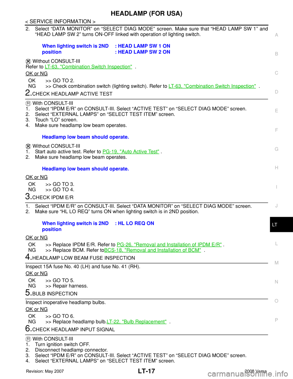
6.CHECK HEADLAMP INPUT SIGNAL
With CONSULT-III
1. Turn ignition switch OFF.
2. Disconnect headlamp connector.
3. Select “IPDM E/R” on CONSULT-III. Select “ACTIVE TEST” on “SELECT DIAG MODE” screen.
4. Select “EXTERNAL LAMPS” on “SELECT TEST ITEM” screen. When lighting switch is 2ND
position: HEAD LAMP SW 1 ON
: HEAD LAMP SW 2 ON
Headlamp low beam should operate.
Headlamp low beam should operate.
When lighting switch is 2ND
position: HL LO REQ ON
Page 2155 of 2771
LT-18
< SERVICE INFORMATION >
HEADLAMP (FOR USA)
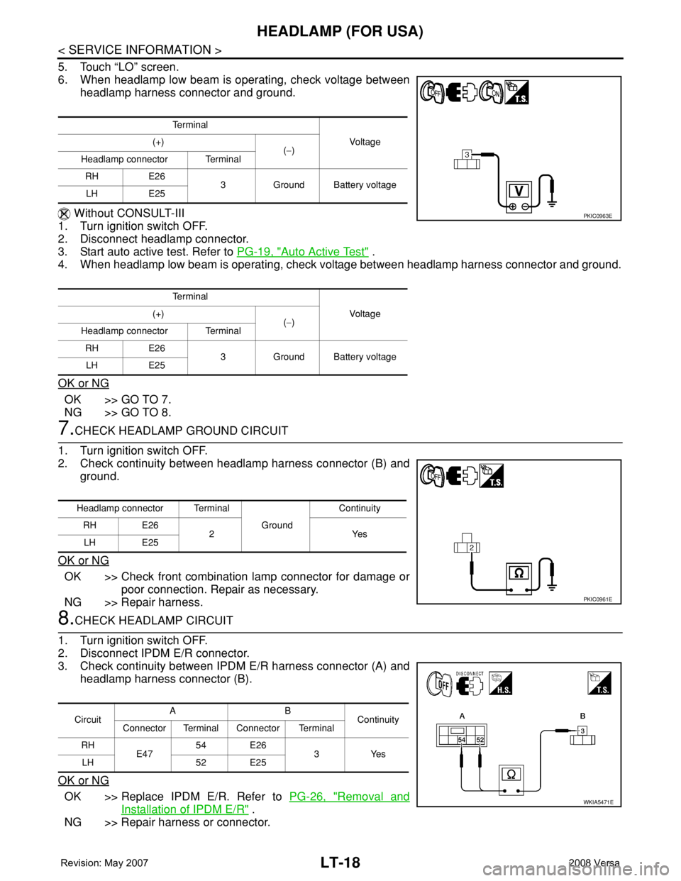
5. Touch “LO” screen.
6. When headlamp low beam is operating, check voltage between
headlamp harness connector and ground.
Without CONSULT-III
1. Turn ignition switch OFF.
2. Disconnect headlamp connector.
3. Start auto active test. Refer to PG-19, "
Auto Active Test" .
4. When headlamp low beam is operating, check voltage between headlamp harness connector and ground.
OK or NG
OK >> GO TO 7.
NG >> GO TO 8.
7.CHECK HEADLAMP GROUND CIRCUIT
1. Turn ignition switch OFF.
2. Check continuity between headlamp harness connector (B) and
ground.
OK or NG
OK >> Check front combination lamp connector for damage or
poor connection. Repair as necessary.
NG >> Repair harness.
8.CHECK HEADLAMP CIRCUIT
1. Turn ignition switch OFF.
2. Disconnect IPDM E/R connector.
3. Check continuity between IPDM E/R harness connector (A) and
headlamp harness connector (B).
OK or NG
OK >> Replace IPDM E/R. Refer to PG-26, "Removal and
Installation of IPDM E/R" .
NG >> Repair harness or connector.
Te r m i n a l
Vo l ta g e (+)
(−)
Headlamp connector Terminal
RH E26
3 Ground Battery voltage
LH E25
Te r m i n a l
Vo l ta g e (+)
(−)
Headlamp connector Terminal
RH E26
3 Ground Battery voltage
LH E25
PKIC0963E
Headlamp connector Terminal
Ground Continuity
RH E26
2Yes
LH E25
PKIC0961E
CircuitAB
Continuity
Connector Terminal Connector Terminal
RH
E4754 E26
3Yes
LH 52 E25
WKIA5471E
Page 2156 of 2771
HEADLAMP (FOR USA)
LT-19
< SERVICE INFORMATION >
C
D
E
F
G
H
I
J
L
MA
B
LT
N
O
P
Headlamp Low Beam Does Not Illuminate (One Side)INFOID:0000000001704375
1.HEADLAMP LOW BEAM FUSE INSPECTION
Inspect 15A fuse No. 40 (LH) and fuse No. 41 (RH).
OK or NG
OK >> GO TO 2.
NG >> Repair harness.
2.CHECK BULB
Check bulb of headlamp which does not illuminate.
OK or NG
OK >> GO TO 3.
NG >> Replace bulb. Refer to LT-22, "
Bulb Replacement" .
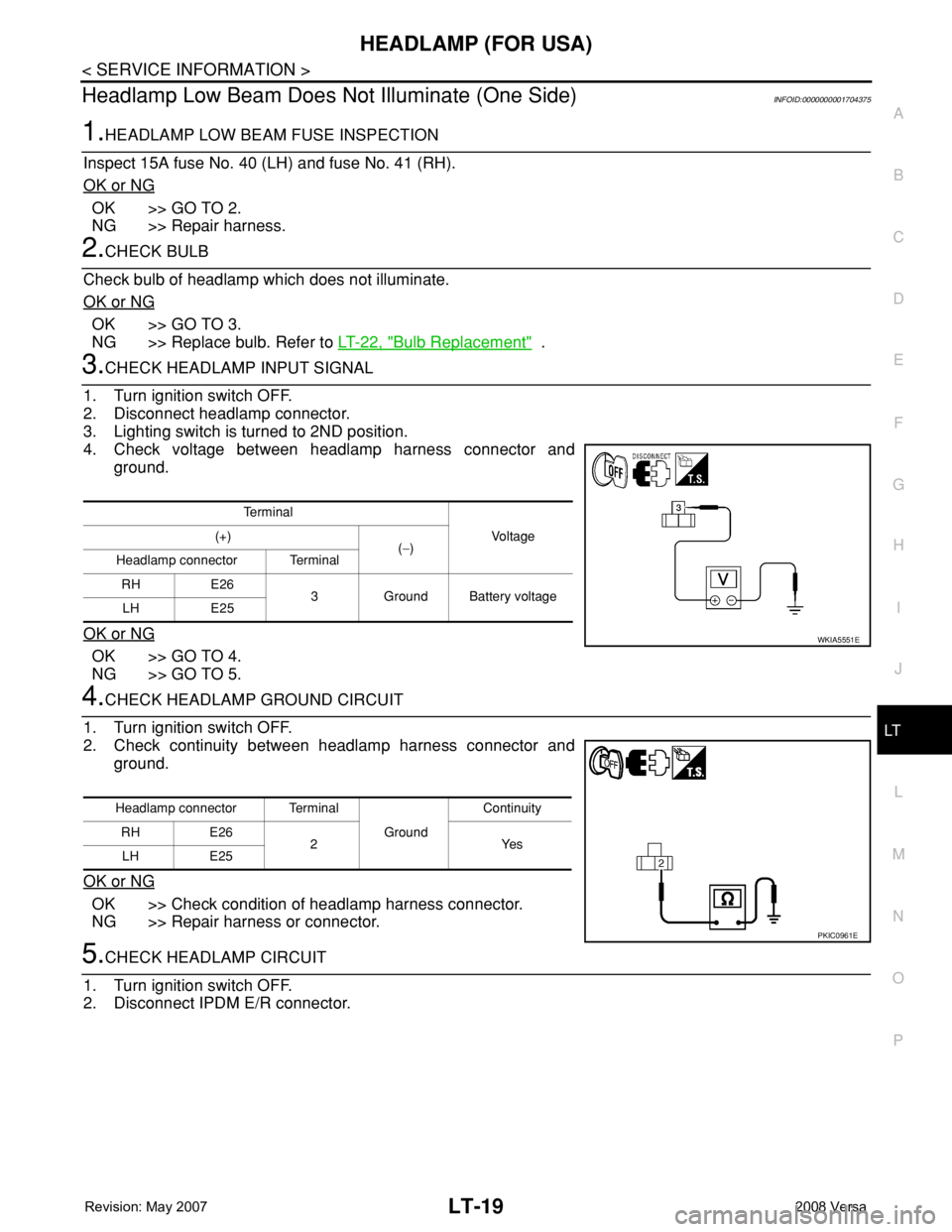
3.CHECK HEADLAMP INPUT SIGNAL
1. Turn ignition switch OFF.
2. Disconnect headlamp connector.
3. Lighting switch is turned to 2ND position.
4. Check voltage between headlamp harness connector and
ground.
OK or NG
OK >> GO TO 4.
NG >> GO TO 5.
4.CHECK HEADLAMP GROUND CIRCUIT
1. Turn ignition switch OFF.
2. Check continuity between headlamp harness connector and
ground.
OK or NG
OK >> Check condition of headlamp harness connector.
NG >> Repair harness or connector.
5.CHECK HEADLAMP CIRCUIT
1. Turn ignition switch OFF.
2. Disconnect IPDM E/R connector.
Te r m i n a l
Vo l ta g e (+)
(−)
Headlamp connector Terminal
RH E26
3 Ground Battery voltage
LH E25
WKIA5551E
Headlamp connector Terminal
Ground Continuity
RH E26
2Yes
LH E25
PKIC0961E