2008 NISSAN TIIDA Power window
[x] Cancel search: Power windowPage 2449 of 2771

PG-16
< SERVICE INFORMATION >
IPDM E/R (INTELLIGENT POWER DISTRIBUTION MODULE ENGINE ROOM)
IPDM E/R (INTELLIGENT POWER DISTRIBUTION MODULE ENGINE
ROOM)
System DescriptionINFOID:0000000001704697
• IPDM E/R (Intelligent Power Distribution Module Engine Room) integrates the relay box and fuse block
which were originally placed in engine compartment. It controls integrated relays via IPDM E/R control cir-
cuits.
• IPDM E/R-integrated control circuits perform ON-OFF operation of relays, CAN communication control, oil
pressure switch signal reception, etc.
• It controls operation of each electrical component via ECM, BCM and CAN communication lines.
CAUTION:
None of the IPDM E/R integrated relays can be removed.
SYSTEMS CONTROLLED BY IPDM E/R
1. Lamp control
Using CAN communication lines, it receives signals from the BCM and controls the following lamps:
• Headlamps (High, Low)
• Parking lamps
• Tail and license plate lamps
• Front fog lamps
2. Wiper control
Using CAN communication lines, it receives signals from the BCM and controls the front wipers.
3. Rear window defogger relay control
Using CAN communication lines, it receives signals from the BCM and controls the rear window defogger
relay.
4. A/C compressor control
Using CAN communication lines, it receives signals from the ECM and controls the A/C compressor
(magnet clutch).
5. Starter control
Using CAN communication lines, it receives signals from the BCM and controls the starter relay.
6. Cooling fan control
Using CAN communication lines, it receives signals from the ECM and controls the cooling fan relays.
7. Horn control
Using CAN communication lines, it receives signals from the BCM and controls the horn relay.
8. Daytime light system control (Canada only)
Using CAN communication lines, it receives signals from the BCM and controls the daytime light relay.
CAN COMMUNICATION LINE CONTROL
With CAN communication, by connecting each control unit using two communication lines (CAN L-line, CAN
H-line), it is possible to transmit a maximum amount of information with minimum wiring. Each control unit can
transmit and receive data, and reads necessary information only.
1. Fail-safe control
• When CAN communication with other control units is impossible, IPDM E/R performs fail-safe control.
After CAN communication returns to normal operation, it also returns to normal control.
• Operation of control parts by IPDM E/R during fail-safe mode is as follows:
Controlled system Fail-safe mode
Headlamp• With the ignition switch ON, headlamp low relay is ON, headlamp high relays are OFF, and
daytime light system (Canada only) is OFF.
• With the ignition switch OFF, the headlamp relays are OFF.
Tail, license plate and parking lamps • With the ignition switch ON, the tail lamp relay is ON.
• With the ignition switch OFF, the tail lamp relay is OFF.
Cooling fan• With the ignition switch ON, cooling fan relay-1, relay-2, and relay-3 are ON.
• With the ignition switch OFF, all cooling fan relays are OFF.
Front wiperUntil the ignition switch is turned off, the front wiper relays remain in the same status they
were in just before fail−safe control was initiated.
Page 2450 of 2771
IPDM E/R (INTELLIGENT POWER DISTRIBUTION MODULE ENGINE ROOM)
PG-17
< SERVICE INFORMATION >
C
D
E
F
G
H
I
J
L
MA
B
PG
N
O
P
IPDM E/R STATUS CONTROL
In order to save power, IPDM E/R switches status by itself based on each operating condition.
1. CAN communication status
• CAN communication is normally performed with other control units.
• Individual unit control by IPDM E/R is normally performed.
• When sleep request signal is received from BCM, mode is switched to sleep waiting status.
2. Sleep waiting status
• Process to stop CAN communication is activated.
• All systems controlled by IPDM E/R are stopped. When 1 second has elapsed after CAN communica-
tion with other control units is stopped, mode switches to sleep status.
3. Sleep status
• IPDM E/R operates in low current-consumption mode.
• CAN communication is stopped.
• When a change in CAN communication signal is detected, mode switches to CAN communication sta-
tus.
• When a change in ignition switch signal is detected, mode switches to CAN communication status.
CAN Communication System DescriptionINFOID:0000000001704698
Refer to LAN-6, "System Description".
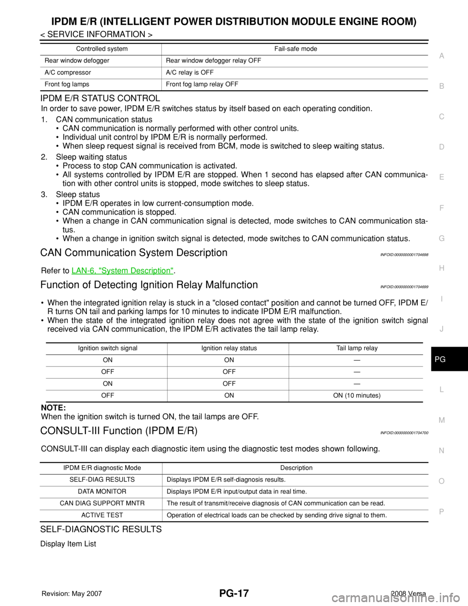
Function of Detecting Ignition Relay MalfunctionINFOID:0000000001704699
• When the integrated ignition relay is stuck in a "closed contact" position and cannot be turned OFF, IPDM E/
R turns ON tail and parking lamps for 10 minutes to indicate IPDM E/R malfunction.
• When the state of the integrated ignition relay does not agree with the state of the ignition switch signal
received via CAN communication, the IPDM E/R activates the tail lamp relay.
NOTE:
When the ignition switch is turned ON, the tail lamps are OFF.
CONSULT-III Function (IPDM E/R)INFOID:0000000001704700
CONSULT-III can display each diagnostic item using the diagnostic test modes shown following.
SELF-DIAGNOSTIC RESULTS
Display Item List
Rear window defogger Rear window defogger relay OFF
A/C compressor A/C relay is OFF
Front fog lamps Front fog lamp relay OFFControlled system Fail-safe mode
Ignition switch signal Ignition relay status Tail lamp relay
ON ON —
OFF OFF —
ON OFF —
OFF ON ON (10 minutes)
IPDM E/R diagnostic Mode Description
SELF-DIAG RESULTS Displays IPDM E/R self-diagnosis results.
DATA MONITOR Displays IPDM E/R input/output data in real time.
CAN DIAG SUPPORT MNTR The result of transmit/receive diagnosis of CAN communication can be read.
ACTIVE TEST Operation of electrical loads can be checked by sending drive signal to them.
Page 2452 of 2771
IPDM E/R (INTELLIGENT POWER DISTRIBUTION MODULE ENGINE ROOM)
PG-19
< SERVICE INFORMATION >
C
D
E
F
G
H
I
J
L
MA
B
PG
N
O
P
*1 Perform monitoring of IPDM E/R data with the ignition switch ON. When the ignition switch is in ACC position, display may not be cor-
rect.
*2 This item is displayed, but does not function.
CAN DIAG SUPPORT MNTR
Refer to LAN-8 .
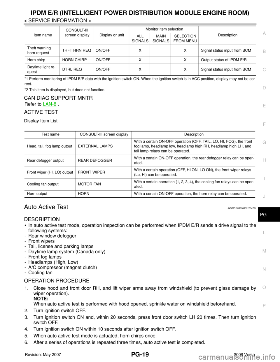
ACTIVE TEST
Display Item List
Auto Active TestINFOID:0000000001704701
DESCRIPTION
• In auto active test mode, operation inspection can be performed when IPDM E/R sends a drive signal to the
following systems:
- Rear window defogger
- Front wipers
- Tail, license and parking lamps
- Daytime lamp system (Canada only)
- Front fog lamps
- Headlamps (High, Low)
- A/C compressor (magnet clutch)
- Cooling fan
OPERATION PROCEDURE
1. Close hood and front door RH, and lift wiper arms away from windshield (to prevent glass damage by
wiper operation).
NOTE:
When auto active test is performed with hood opened, sprinkle water on windshield beforehand.
2. Turn ignition switch OFF.
3. Turn ignition switch ON and, within 20 seconds, press front door switch LH 20 times. Then turn ignition
switch OFF.
4. Turn ignition switch ON within 10 seconds after ignition switch OFF.
5. When auto active test mode is actuated, horn chirps once.
6. After a series of operations is repeated three times, auto active test is completed.
Theft warning
horn requestTHFT HRN REQ ON/OFF X X Signal status input from BCM
Horn chirp HORN CHIRP ON/OFF X X Output status of IPDM E/R
Daytime light re-
questDTRL REQ ON/OFF X X Signal status input from BCM Item nameCONSULT-III
screen display Display or unitMonitor item selection
Description
ALL
SIGNALSMAIN
SIGNALSSELECTION
FROM MENU
Test name CONSULT-III screen display Description
Head, tail, fog lamp output EXTERNAL LAMPSWith a certain ON-OFF operation (OFF, TAIL, LO, HI, FOG), the front
fog lamp, headlamp low, headlamp high RH, headlamp high LH, and
tail lamp relays can be operated.
Rear defogger output REAR DEFOGGERWith a certain ON-OFF operation, the rear defogger relay can be oper-
ated.
Front wiper (HI, LO) output FRONT WIPERWith a certain operation (OFF, HI ON, LO ON), the front wiper relays
(Lo, Hi) can be operated.
Cooling fan output MOTOR FANWith a certain operation (1, 2, 3, 4), the cooling fan relays can be oper-
ated.
Horn output HORN With a certain ON-OFF operation, the horn relay can be operated.
Page 2453 of 2771
PG-20
< SERVICE INFORMATION >
IPDM E/R (INTELLIGENT POWER DISTRIBUTION MODULE ENGINE ROOM)
NOTE:
When auto active test mode has to be cancelled halfway, turn ignition switch OFF.
CAUTION:
Be sure to perform BL-37, "
Door Switch Check (Hatchback)" when the auto active test cannot be
performed.
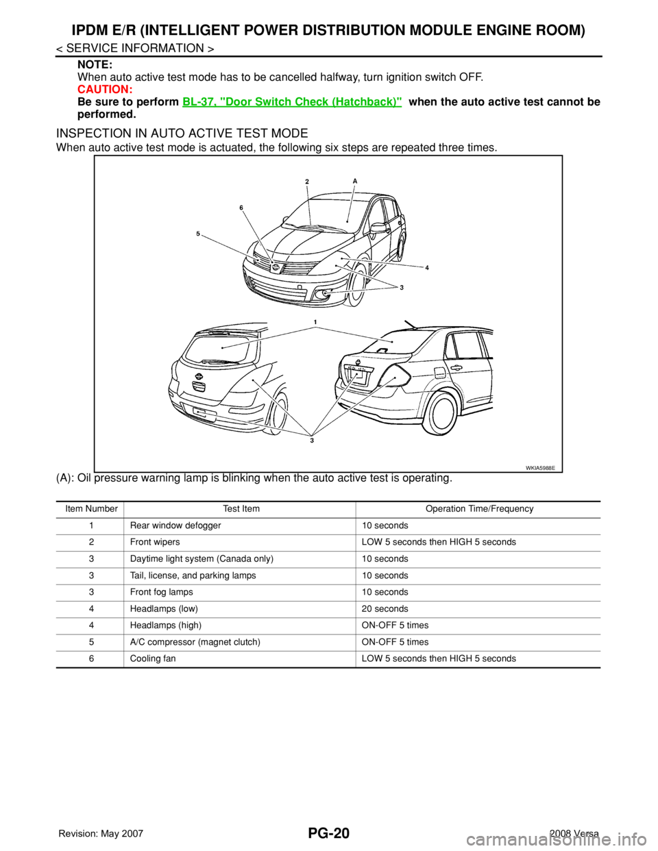
INSPECTION IN AUTO ACTIVE TEST MODE
When auto active test mode is actuated, the following six steps are repeated three times.
(A): Oil pressure warning lamp is blinking when the auto active test is operating.
WKIA5988E
Item Number Test Item Operation Time/Frequency
1 Rear window defogger 10 seconds
2 Front wipers LOW 5 seconds then HIGH 5 seconds
3 Daytime light system (Canada only) 10 seconds
3 Tail, license, and parking lamps 10 seconds
3 Front fog lamps 10 seconds
4 Headlamps (low) 20 seconds
4 Headlamps (high) ON-OFF 5 times
5 A/C compressor (magnet clutch) ON-OFF 5 times
6 Cooling fan LOW 5 seconds then HIGH 5 seconds
Page 2454 of 2771
IPDM E/R (INTELLIGENT POWER DISTRIBUTION MODULE ENGINE ROOM)
PG-21
< SERVICE INFORMATION >
C
D
E
F
G
H
I
J
L
MA
B
PG
N
O
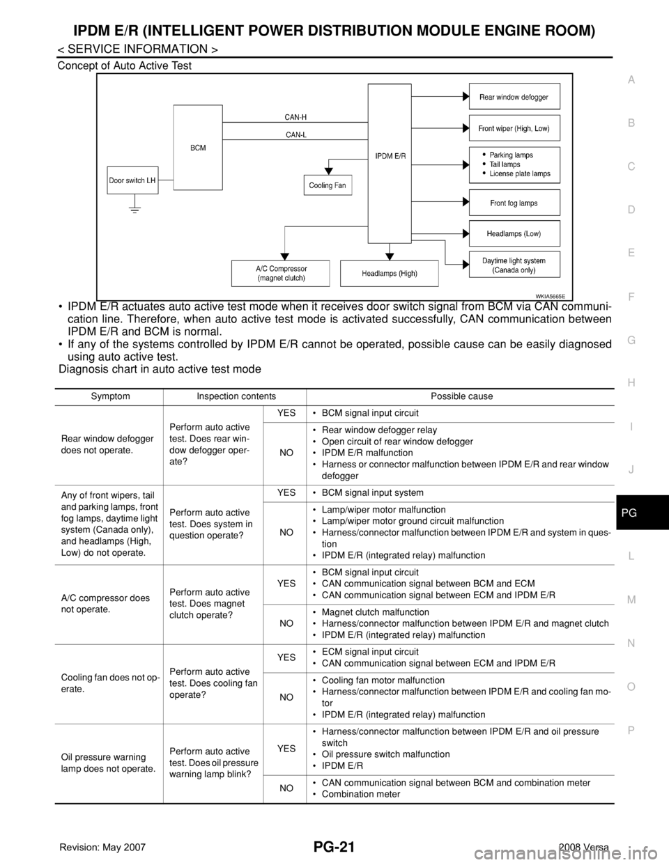
P Concept of Auto Active Test
• IPDM E/R actuates auto active test mode when it receives door switch signal from BCM via CAN communi-
cation line. Therefore, when auto active test mode is activated successfully, CAN communication between
IPDM E/R and BCM is normal.
• If any of the systems controlled by IPDM E/R cannot be operated, possible cause can be easily diagnosed
using auto active test.
Diagnosis chart in auto active test mode
WKIA5665E
Symptom Inspection contents Possible cause
Rear window defogger
does not operate.Perform auto active
test. Does rear win-
dow defogger oper-
ate?YES • BCM signal input circuit
NO• Rear window defogger relay
• Open circuit of rear window defogger
• IPDM E/R malfunction
• Harness or connector malfunction between IPDM E/R and rear window
defogger
Any of front wipers, tail
and parking lamps, front
fog lamps, daytime light
system (Canada only),
and headlamps (High,
Low) do not operate.Perform auto active
test. Does system in
question operate?YES • BCM signal input system
NO• Lamp/wiper motor malfunction
• Lamp/wiper motor ground circuit malfunction
• Harness/connector malfunction between IPDM E/R and system in ques-
tion
• IPDM E/R (integrated relay) malfunction
A/C compressor does
not operate.Perform auto active
test. Does magnet
clutch operate?YES• BCM signal input circuit
• CAN communication signal between BCM and ECM
• CAN communication signal between ECM and IPDM E/R
NO• Magnet clutch malfunction
• Harness/connector malfunction between IPDM E/R and magnet clutch
• IPDM E/R (integrated relay) malfunction
Cooling fan does not op-
erate.Perform auto active
test. Does cooling fan
operate?YES• ECM signal input circuit
• CAN communication signal between ECM and IPDM E/R
NO• Cooling fan motor malfunction
• Harness/connector malfunction between IPDM E/R and cooling fan mo-
tor
• IPDM E/R (integrated relay) malfunction
Oil pressure warning
lamp does not operate.Perform auto active
test. Does oil pressure
warning lamp blink?YES• Harness/connector malfunction between IPDM E/R and oil pressure
switch
• Oil pressure switch malfunction
• IPDM E/R
NO• CAN communication signal between BCM and combination meter
• Combination meter
Page 2458 of 2771

IPDM E/R (INTELLIGENT POWER DISTRIBUTION MODULE ENGINE ROOM)
PG-25
< SERVICE INFORMATION >
C
D
E
F
G
H
I
J
L
MA
B
PG
N
O
PIPDM E/R Power/Ground Circuit InspectionINFOID:0000000001704704
1.FUSE AND FUSIBLE LINK INSPECTION
Check that the following fusible links or IPDM E/R fuses are not blown.
OK or NG
OK >> GO TO 2.
NG >> Replace fuse or fusible link.
2.POWER CIRCUIT INSPECTION
1. Turn ignition switch OFF.
2. Disconnect IPDM E/R harness connector E42.
3. Check voltage between IPDM E/R harness connector E42 terminals 1, 2 and ground.
50 V Front fog lamp (LH)Output ON or
STARTLighting
switch must
be in the 2ND
position
(LOW beam
is ON) and
the front fog
lamp switchOFF 0V
ON Battery voltage
51 W Front fog lamp (RH) OutputON or
STARTLighting
switch must
be in the 2ND
position
(LOW beam
is ON) and
the front fog
lamp switchOFF 0V
ON Battery voltage
52 LLH Low beam head-
lampOutput — Lighting switch in 2nd position Battery voltage
54 PRH Low beam head-
lampOutput — Lighting switch in 2nd position Battery voltage
55 GLH High beam head-
lampOutput —Lighting switch in 2nd position
and placed in HIGH or PASS
positionBattery voltage
56 YRH High beam head-
lampOutput —Lighting switch in 2nd position
and placed in HIGH or PASS
positionBattery voltage
59 B Ground Input — — 0V
60 RRear window defogger
relayOutputON or
STARTRear defogger Switch ON Battery voltage
Rear defogger Switch OFF 0V Te r m i n a lWire
colorSignal nameSignal
input/
outputMeasuring condition
Reference value
(Approx.) Ignition
switchOperation or condition
Terminal No. Signal name Fuse, fusible link No.
1, 2 Battery power a, b, d
Page 2484 of 2771

HARNESS
PG-51
< SERVICE INFORMATION >
C
D
E
F
G
H
I
J
L
MA
B
PG
N
O
P
E3 B100 GR/5 : Fuel level sensor unit and fuel pump
G5 B101 W/16 : To M12
G5 B102 W/24 : To M13
F4 B103 B/2 : Console power socket
B4 B104 GR/3: EVAP control system pressure sen-
sor
B3 B105 B/2 : EVAP canister vent control valve
G5 B106 W/4 : To M11
A2 B107 BR/6 : Rear combination lamp RH
F4 B108 W/3 : Front door switch RH
F4 B109 Y/2 : Front RH side air bag module
F4 B110 W/10 : To B300
E5 B111 Y/2 : RH side air bag (satellite) sensor
F4 B112 W/3 : Seat belt buckle switch RH
G3 B113 Y/12 : Air bag diagnosis sensor unit
E4 B114 — : Body ground
E4 B115 Y/2 : Front RH seat belt pre-tensioner
C3 B116 W/1 : Rear door switch RH
E3 B117 — : Body ground
C2 B118 Y/2 : RH side curtain air bag module
E4 B119 W/8 : To D301
G5 B120 W/24 : To M14
C3 B121 W/32 : Bluetooth control unit
B3 B122 GR/1 : Bluetooth control unit
E3 B123 B/2 : Rear wheel sensor LH
D4 B124 B/2 : Rear wheel sensor RH
F4 B125 GR/2 : Front console antenna
D3 B126 GR/2 : Rear floor antenna
B2 B127 W/3: Trunk lamp switch and trunk release
solenoid
B1 B128 BR/2 : Trunk lid opener switch
B1 B129 GR/2 : Trunk opener request switch
C2 B130 B/1 : Condenser-1
C2 B131 B/1 : Condenser-1
C3 B132 — : Body ground
E5 B138 B/3 : Belt tension sensor
D1 B139 — : Body ground
C2 B140 B/1 : Rear window defogger (+)
D1 B141 B/1 : Rear window defogger (-)
B2 B142 W/3 : Trunk key cylinder switch
B1 B143 BR/2 : License plate lamp RH
B2 B144 BR/2 : License plate lamp LH
Page 2486 of 2771
HARNESS
PG-53
< SERVICE INFORMATION >
C
D
E
F
G
H
I
J
L
MA
B
PG
N
O
P
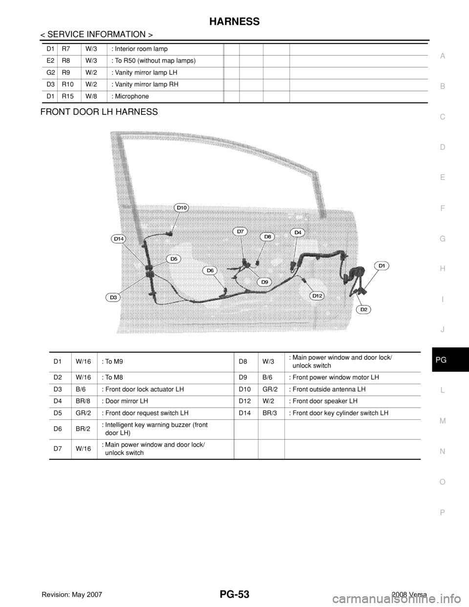
FRONT DOOR LH HARNESS
D1 R7 W/3 : Interior room lamp
E2 R8 W/3 : To R50 (without map lamps)
G2 R9 W/2 : Vanity mirror lamp LH
D3 R10 W/2 : Vanity mirror lamp RH
D1 R15 W/8 : Microphone
D1 W/16 : To M9 D8 W/3: Main power window and door lock/
unlock switch
D2 W/16 : To M8 D9 B/6 : Front power window motor LH
D3 B/6 : Front door lock actuator LH D10 GR/2 : Front outside antenna LH
D4 BR/8 : Door mirror LH D12 W/2 : Front door speaker LH
D5 GR/2 : Front door request switch LH D14 BR/3 : Front door key cylinder switch LH
D6 BR/2: Intelligent key warning buzzer (front
door LH)
D7 W/16: Main power window and door lock/
unlock switch