2008 NISSAN TEANA hood open
[x] Cancel search: hood openPage 2409 of 5121
EXT-20
< ON-VEHICLE REPAIR >
COWL TOP
COWL TOP
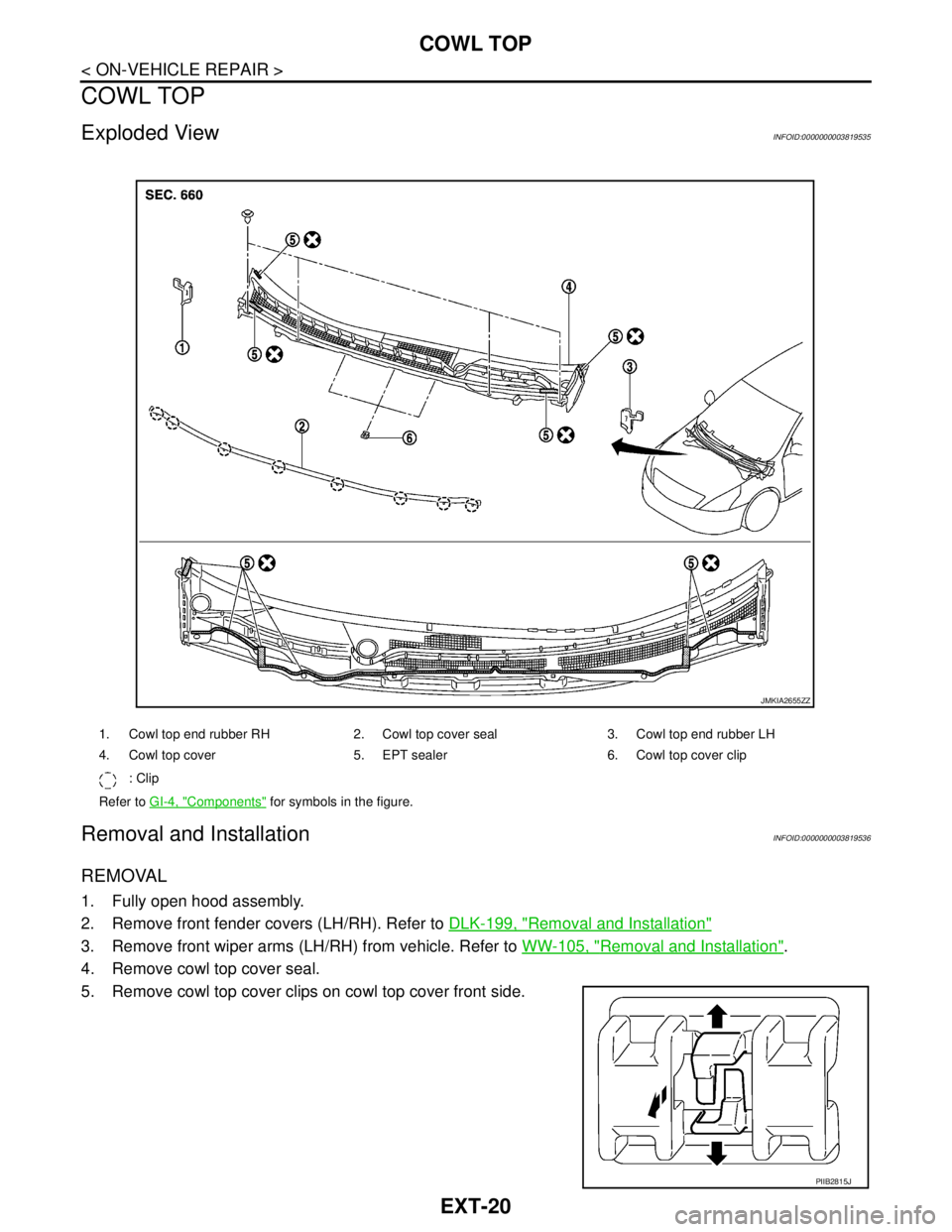
Exploded ViewINFOID:0000000003819535
Removal and InstallationINFOID:0000000003819536
REMOVAL
1. Fully open hood assembly.
2. Remove front fender covers (LH/RH). Refer to DLK-199, "
Removal and Installation"
3. Remove front wiper arms (LH/RH) from vehicle. Refer to WW-105, "Removal and Installation".
4. Remove cowl top cover seal.
5. Remove cowl top cover clips on cowl top cover front side.
1. Cowl top end rubber RH 2. Cowl top cover seal 3. Cowl top end rubber LH
4. Cowl top cover 5. EPT sealer 6. Cowl top cover clip
: Clip
Refer to GI-4, "
Components" for symbols in the figure.
JMKIA2655ZZ
PIIB2815J
Page 2599 of 5121
HA-30
< ON-VEHICLE MAINTENANCE >
REFRIGERATION SYSTEM
REFRIGERATION SYSTEM
InspectionINFOID:0000000003795977
1.CHECK BLOWER MOTOR OPERATION
Check blower motor operation. Refer to the following.
HAC-68, "
ComponentFunctionCheck" (WITHOUT 7 INCH DISPLAY)
HAC-193, "
ComponentFunctionCheck" (WITH 7 INCH DISPLAY)
Is the inspection result normal?
YES >> GO TO 2.
NO >> Repair or replace the parts according to the inspection results.
2.CHECK COMPRESSOR OPERATION
Check compressor operation. Refer to the following.
HAC-72, "
Component Function Check" (WITHOUT 7 INCH DISPLAY)
HAC-197, "
Component Function Check" (WITH 7 INCH DISPLAY)
Is the inspection result normal?
YES >> GO TO 3.
NO >> Repair or replace the parts according to the inspection results.
3.CHECK REFRIGERANT CYCLE PRESSURE
Connect recovery/recycling recharging equipment to the vehicle and perform the diagnosis with the gauge
pressure. Refer to HA-8, "
Trouble Diagnosis For Unusual Pressure".
Is the inspection result normal?
YES >> Perform the performance test. Refer to HA-30, "Performance Chart".
NO >> Repair or replace the parts according to the inspection results.
Performance ChartINFOID:0000000003795978
TEST CONDITION
Testing must be performed as per the following:
TEST READING
Recirculating-to-discharge Air Temperature Table
Vehicle condition Indoors or in the shade (in a well-ventilated place)
Doors Closed
Door windows Open
Hood Open
Temperature control switch or dial Max. COLD
Mode switch
(Ventilation) set
Intake switch
(Recirculation) set
Fan (blower) speedMax. speed set
Engine speed Idle speed
Operate the air conditioning system for 10 minutes before taking measurements.
Inside air (Recirculating air) at blower assembly inlet
Discharge air temperature at center ventilator
°C (°F) Relative humidity
%Air temperature
°C (°F)
50 - 6025 (77) 8.4 - 10.9 (47 - 52)
30 (86) 12.3 - 15.3 (54 - 60)
35 (95) 15.8 - 19.2 (60 - 67)
Page 3054 of 5121
IP-14
< ON-VEHICLE REPAIR >
INSTRUMENT PANEL ASSEMBLY
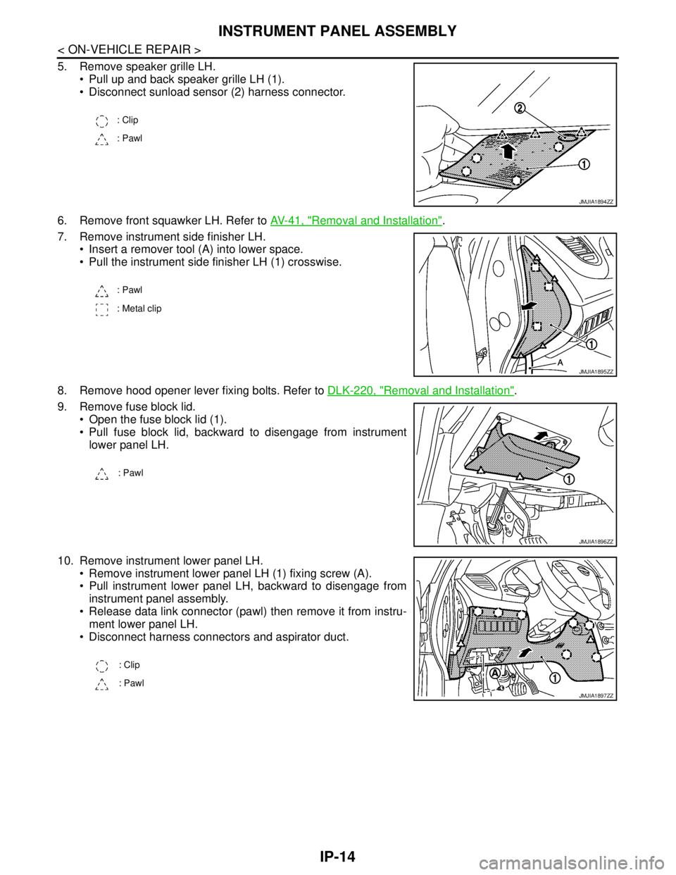
5. Remove speaker grille LH.
Pull up and back speaker grille LH (1).
Disconnect sunload sensor (2) harness connector.
6. Remove front squawker LH. Refer to AV-41, "
Removal and Installation".
7. Remove instrument side finisher LH.
Insert a remover tool (A) into lower space.
Pull the instrument side finisher LH (1) crosswise.
8. Remove hood opener lever fixing bolts. Refer to DLK-220, "
Removal and Installation".
9. Remove fuse block lid.
Open the fuse block lid (1).
Pull fuse block lid, backward to disengage from instrument
lower panel LH.
10. Remove instrument lower panel LH.
Remove instrument lower panel LH (1) fixing screw (A).
Pull instrument lower panel LH, backward to disengage from
instrument panel assembly.
Release data link connector (pawl) then remove it from instru-
ment lower panel LH.
Disconnect harness connectors and aspirator duct.
: Clip
: Pawl
JMJIA1894ZZ
: Pawl
: Metal clip
JMJIA1895ZZ
: Pawl
JMJIA1896ZZ
: Clip
: Pawl
JMJIA1897ZZ
Page 3063 of 5121
CENTER CONSOLE ASSEMBLY
IP-23
< ON-VEHICLE REPAIR >
C
D
E
F
G
H
I
K
L
MA
B
IP
N
O
P
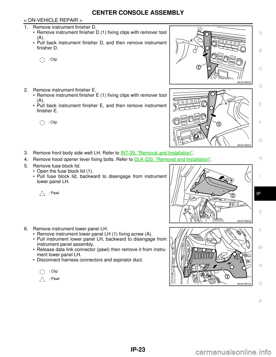
1. Remove instrument finisher D.
Remove instrument finisher D (1) fixing clips with remover tool
(A).
Pull back instrument finisher D, and then remove instrument
finisher D.
2. Remove instrument finisher E.
Remove instrument finisher E (1) fixing clips with remover tool
(A).
Pull back instrument finisher E, and then remove instrument
finisher E.
3. Remove front body side welt LH. Refer to INT-39, "
Removal and Installation".
4. Remove hood opener lever fixing bolts. Refer to DLK-220, "
Removal and Installation".
5. Remove fuse block lid.
Open the fuse block lid (1).
Pull fuse block lid, backward to disengage from instrument
lower panel LH.
6. Remove instrument lower panel LH.
Remove instrument lower panel LH (1) fixing screw (A).
Pull instrument lower panel LH, backward to disengage from
instrument panel assembly.
Release data link connector (pawl) then remove it from instru-
ment lower panel LH.
Disconnect harness connectors and aspirator duct.
: Clip
JMJIA1892ZZ
: Clip
JMJIA1893ZZ
: Pawl
JMJIA1896ZZ
: Clip
: Pawl
JMJIA1897ZZ
Page 3193 of 5121
GENERAL MAINTENANCE
MA-5
< ON-VEHICLE MAINTENANCE >
C
D
E
F
G
H
I
J
K
L
MB
MAN
OA
ON-VEHICLE MAINTENANCE
GENERAL MAINTENANCE
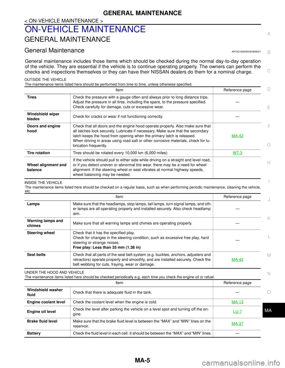
General MaintenanceINFOID:0000000003858221
General maintenance includes those items which should be checked during the normal day-to-day operation
of the vehicle. They are essential if the vehicle is to continue operating properly. The owners can perform the
checks and inspections themselves or they can have their NISSAN dealers do them for a nominal charge.
OUTSIDE THE VEHICLE
The maintenance items listed here should be performed from time to time, unless otherwise specified.
INSIDE THE VEHICLE
The maintenance items listed here should be checked on a regular basis, such as when performing periodic maintenance, cleaning the vehicle,
etc.
UNDER THE HOOD AND VEHICLE
The maintenance items listed here should be checked periodically e.g. each time you check the engine oil or refuel.
Item Reference page
TiresCheck the pressure with a gauge often and always prior to long distance trips.
Adjust the pressure in all tires, including the spare, to the pressure specified.
Check carefully for damage, cuts or excessive wear.—
Windshield wiper
bladesCheck for cracks or wear if not functioning correctly. —
Doors and engine
hoodCheck that all doors and the engine hood operate properly. Also make sure that
all latches lock securely. Lubricate if necessary. Make sure that the secondary
latch keeps the hood from opening when the primary latch is released.
When driving in areas using road salt or other corrosive materials, check for lu-
brication frequently.MA-42
Tire rotationTires should be rotated every 10,000 km (6,000 miles).WT-3
Wheel alignment and
balanceIf the vehicle should pull to either side while driving on a straight and level road,
or if you detect uneven or abnormal tire wear. there may be a need for wheel
alignment. If the steering wheel or seat vibrates at normal highway speeds,
wheel balancing may be needed.
Item Reference page
LampsMake sure that the headlamps, stop lamps, tail lamps, turn signal lamps, and oth-
er lamps are all operating properly and installed securely. Also check headlamp
aim.—
Warning lamps and
chimesMake sure that all warning lamps and chimes are operating properly. —
Steering wheelCheck that it has the specified play.
Check for changes in the steering condition, such as excessive free play, hard
steering or strange noises.
Free play: Less than 35 mm (1.38 in)—
Seat beltsCheck that all parts of the seat belt system (e.g. buckles, anchors, adjusters and
retractors) operate properly and smoothly, and are installed securely. Check the
belt webbing for cuts, fraying, wear or damage.MA-42
Item Reference page
Windshield washer
fluidCheck that there is adequate fluid in the tank. —
Engine coolant levelCheck the coolant level when the engine is cold.MA-13
Engine oil levelCheck the level after parking the vehicle on a level spot and turning off the en-
gine.LU-7
Brake fluid levelMake sure that the brake fluid level is between the “MAX” and “MIN” lines on the
reservoir.MA-37
BatteryCheck the fluid level in each cell. It should be between the “MAX” and “MIN” lines. —
Page 3230 of 5121
MA-42
< ON-VEHICLE MAINTENANCE >
BODY MAINTENANCE
BODY MAINTENANCE
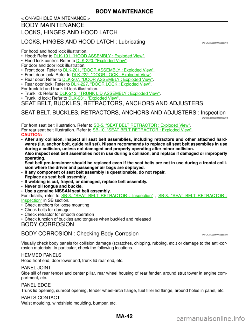
LOCKS, HINGES AND HOOD LATCH
LOCKS, HINGES AND HOOD LATCH : LubricatingINFOID:0000000003858318
For hood and hood lock illustration.
Hood: Refer to DLK-191, "
HOOD ASSEMBLY : Exploded View".
Hood lock control: Refer to DLK-220, "
Exploded View".
For door and door lock illustration.
Front door: Refer to DLK-201, "
DOOR ASSEMBLY : Exploded View".
Front door lock: Refer to DLK-222, "
DOOR LOCK : Exploded View".
Rear door: Refer to DLK-207, "
DOOR ASSEMBLY : Exploded View".
Rear door lock: Refer to DLK-227, "
DOOR LOCK : Exploded View".
For trunk lid and trunk lid lock illustration.
Trunk lid: Refer to DLK-213, "
TRUNK LID ASSEMBLY : Exploded View".
Trunk lid lock: Refer to DLK-231, "
Exploded View".
SEAT BELT, BUCKLES, RETRACTORS, ANCHORS AND ADJUSTERS
SEAT BELT, BUCKLES, RETRACTORS, ANCHORS AND ADJUSTERS : Inspection
INFOID:0000000003858319
For front seat belt illustration. Refer to SB-5, "SEAT BELT RETRACTOR : Exploded View".
For rear seat belt illustration. Refer to SB-10, "
SEAT BELT RETRACTOR : Exploded View".
CAUTION:
After any collision, inspect all seat belt assemblies, including retractors and other attached hard-
wares (I.e. anchor bolt, guide rail set). Nissan recommends to replace all seat belt assemblies in use
during a collision, unless not damaged and properly operating after minor collision.
Also inspect seat belt assemblies not in use during a collision, and replace if damaged or improperly
operating.
Seat belt pre-tensioner should be replaced even if the seat belts are not in use during a frontal colli-
sion where the driver and passenger air bags are deployed.
If any component of seat belt assembly is questionable, do not repair.
Replace as seat belt assembly.
If webbing is cut, frayed, or damaged, replace belt assembly.
Never oil tongue and buckle.
Use a genuine NISSAN seat belt assembly.
For details, refer to SB-3, "
SEAT BELT RETRACTOR : Inspection" , SB-8, "SEAT BELT RETRACTOR :
Inspection" in SB section.
Check anchors for loose mounting
Check belts for damage
Check retractor for smooth operation
Check function of buckles and tongues when buckled and released
BODY CORROSION
BODY CORROSION : Checking Body CorrosionINFOID:0000000003858320
Visually check body panels for collision damage (scratches, chipping, rubbing, etc.) or damage to the anti-cor-
rosion materials. In particular, check the following locations.
HEMMED PANELS
Hood front end, door lower end, trunk lid rear end, etc.
PA N E L J O I N T
Side sill of rear fender and center pillar, rear wheel housing of rear fender, around strut tower in engine com-
partment, etc.
PA N E L E D G E
Trunk lid opening, sunroof opening, fender wheel-arch flange, fuel filler lid flange, around holes in panel, etc.
PARTS CONTACT
Waist moulding, windshield moulding, bumper, etc.
Page 3357 of 5121

MWI
IPDM E/R (INTELLIGENT POWER DISTRIBUTION MODULE ENGINE ROOM)
MWI-103
< ECU DIAGNOSIS >
C
D
E
F
G
H
I
J
K
L
MB A
O
P
ST/INHI RLYIgnition switch ON Off
At engine cranking INHI → ST
The status of starter relay or starter control relay cannot be recognized by
the battery voltage malfunction, etc. when the starter relay is ON and the
starter control relay is OFFUNKWN
DETENT SWIgnition switch ON Press the selector button with se-
lector lever in P position
Selector lever in any position oth-
er than POff
Release the selector button with selector lever in P position On
S/L RLY -REQNone of the conditions below are present Off
Open the driver door after the ignition switch is turned OFF (for a few
seconds)
Press the push-button ignition switch when the steering lock is activat-
edOn
S/L STATESteering lock is activated LOCK
Steering lock is deactivated UNLOCK
[DTC: B210A] is detected UNKWN
DTRL REQNOTE:
The item is indicated, but not monitored.Off
OIL P SWIgnition switch OFF, ACC or engine running Open
Ignition switch ON Close
HOOD SWClose the hood Off
Open the hood On
HL WASHER REQNot operating Off
Headlamp washer operating On
THFT HRN REQNot operating Off
Horn is activated with vehicle security (theft warning) system On
HORN CHIRPNot operating Off
Door locking with Intelligent Key (horn chirp mode)
Door locking with key fob (horn chirp mode)On
CRNRNG LMP REQNOTE:
The item is indicated, but not monitored.Off Monitor Item Condition Value/Status
Page 3363 of 5121
MWI
IPDM E/R (INTELLIGENT POWER DISTRIBUTION MODULE ENGINE ROOM)
MWI-109
< ECU DIAGNOSIS >
C
D
E
F
G
H
I
J
K
L
MB A
O
P
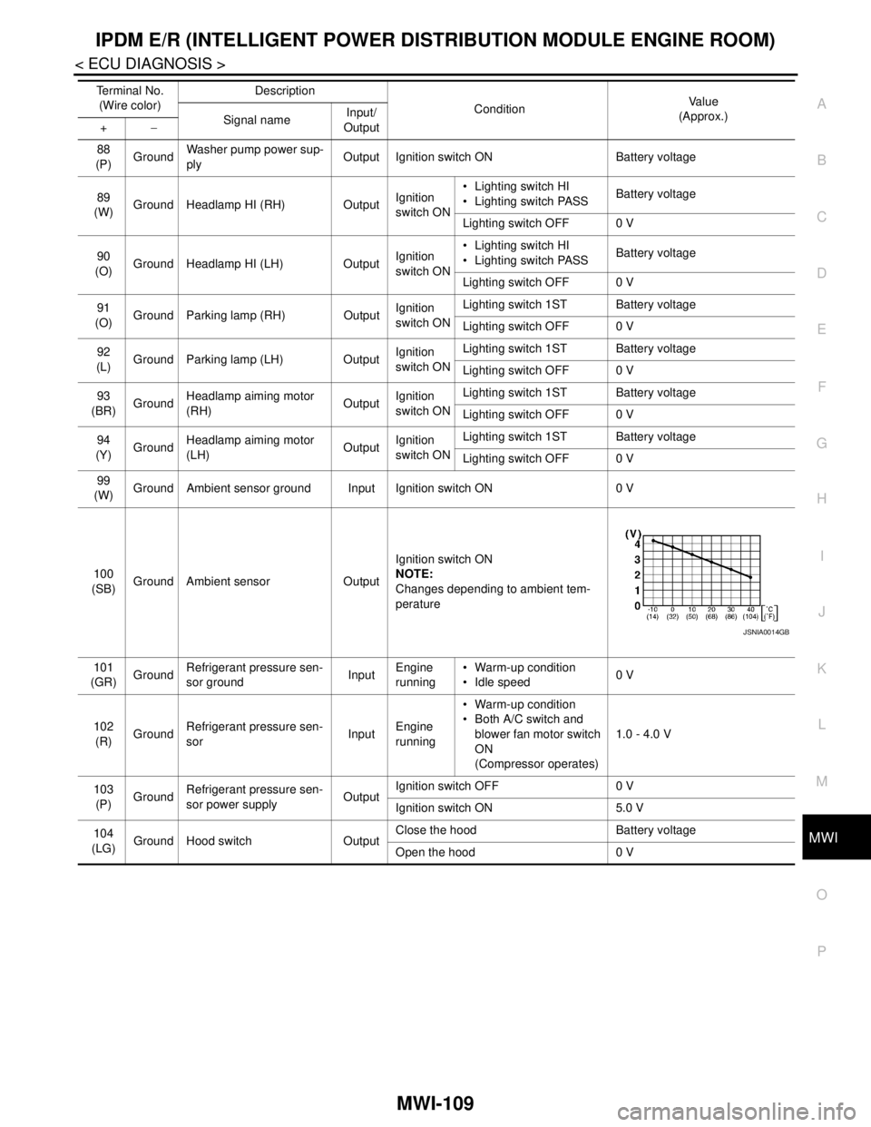
88
(P)GroundWasher pump power sup-
plyOutput Ignition switch ON Battery voltage
89
(W)Ground Headlamp HI (RH) OutputIgnition
switch ON Lighting switch HI
Lighting switch PASSBattery voltage
Lighting switch OFF 0 V
90
(O)Ground Headlamp HI (LH) OutputIgnition
switch ON Lighting switch HI
Lighting switch PASSBattery voltage
Lighting switch OFF 0 V
91
(O)Ground Parking lamp (RH) OutputIgnition
switch ONLighting switch 1ST Battery voltage
Lighting switch OFF 0 V
92
(L)Ground Parking lamp (LH) OutputIgnition
switch ONLighting switch 1ST Battery voltage
Lighting switch OFF 0 V
93
(BR)GroundHeadlamp aiming motor
(RH)OutputIgnition
switch ONLighting switch 1ST Battery voltage
Lighting switch OFF 0 V
94
(Y)GroundHeadlamp aiming motor
(LH)OutputIgnition
switch ONLighting switch 1ST Battery voltage
Lighting switch OFF 0 V
99
(W)Ground Ambient sensor ground Input Ignition switch ON 0 V
100
(SB)Ground Ambient sensor OutputIgnition switch ON
NOTE:
Changes depending to ambient tem-
perature
101
(GR)GroundRefrigerant pressure sen-
sor groundInputEngine
running Warm-up condition
Idle speed0 V
102
(R)GroundRefrigerant pressure sen-
sorInputEngine
running Warm-up condition
Both A/C switch and
blower fan motor switch
ON
(Compressor operates)1.0 - 4.0 V
103
(P)GroundRefrigerant pressure sen-
sor power supplyOutputIgnition switch OFF 0 V
Ignition switch ON 5.0 V
104
(LG)
Ground Hood switch OutputClose the hood Battery voltage
Open the hood 0 V Te r m i n a l N o .
(Wire color)Description
ConditionVa l u e
(Approx.)
Signal nameInput/
Output +−
JSNIA0014GB