2008 NISSAN TEANA fuel cap
[x] Cancel search: fuel capPage 1653 of 5121
![NISSAN TEANA 2008 Service Manual EC-192
< COMPONENT DIAGNOSIS >[VQ25DE, VQ35DE]
P0139, P0159 HO2S2
P0139, P0159 HO2S2
DescriptionINFOID:0000000003856587
The heated oxygen sensor 2, after three way catalyst (manifold),
monitors the ox](/manual-img/5/57391/w960_57391-1652.png "NISSAN TEANA 2008 Service Manual EC-192
< COMPONENT DIAGNOSIS >[VQ25DE, VQ35DE]
P0139, P0159 HO2S2
P0139, P0159 HO2S2
DescriptionINFOID:0000000003856587
The heated oxygen sensor 2, after three way catalyst (manifold),
monitors the ox")
EC-192
< COMPONENT DIAGNOSIS >[VQ25DE, VQ35DE]
P0139, P0159 HO2S2
P0139, P0159 HO2S2
DescriptionINFOID:0000000003856587
The heated oxygen sensor 2, after three way catalyst (manifold),
monitors the oxygen level in the exhaust gas on each bank.
Even if switching characteristics of the air fuel ratio (A/F) sensor 1
are shifted, the air-fuel ratio is controlled to stoichiometric, by the sig-
nal from the heated oxygen sensor 2.
This sensor is made of ceramic zirconia. The zirconia generates volt-
age from approximately 1 V in richer conditions to 0 V in leaner con-
ditions.
Under normal conditions the heated oxygen sensor 2 is not used for
engine control operation.
DTC LogicINFOID:0000000003856588
DTC DETECTION LOGIC
The heated oxygen sensor 2 has a much longer switching time
between rich and lean than the air fuel ratio (A/F) sensor 1. The oxy-
gen storage capacity of the three way catalyst (manifold) causes the
longer switching time. To judge the malfunctions of heated oxygen
sensor 2, ECM monitors whether the switching response of the sen-
sor's voltage is faster than specified during various driving conditions
such as fuel cut.
DTC CONFIRMATION PROCEDURE
1.INSPECTION START
Will CONSULT-III be used?
Will CONSULT-III be used?
YES >> GO TO 2.
NO >> GO TO 5.
2.PRECONDITIONING
If DTC Confirmation Procedure has been previously conducted, always turn ignition switch OFF and wait at
least 10 seconds before conducting the next test.
TESTING CONDITION:
For better results, perform “DTC WORK SUPPORT” at a temperature of 0 to 30 °C (32 to 86 °F).
>> GO TO 3.
3.PERFORM DTC CONFIRMATION PROCEDURE
With CONSULT-III
SEF327R
SEF302U
DTC No. Trouble diagnosis name DTC detecting condition Possible cause
P0139Heated oxygen sensor 2
(bank 1) circuit slow re-
sponse
It takes more time for the sensor to respond be-
tween rich and lean than the specified time. Harness or connectors
(The sensor circuit is open or shorted)
Heated oxygen sensor 2
Fuel pressure
Fuel injector
Intake air leaks P0159Heated oxygen sensor 2
(bank 2) circuit slow re-
sponse
Page 1687 of 5121
![NISSAN TEANA 2008 Service Manual EC-226
< COMPONENT DIAGNOSIS >[VQ25DE, VQ35DE]
P0420, P0430 THREE WAY CATALYST FUNCTION
P0420, P0430 THREE WAY CATALYST FUNCTION
DTC LogicINFOID:0000000003856631
DTC DETECTION LOGIC
The ECM monitors t](/manual-img/5/57391/w960_57391-1686.png "NISSAN TEANA 2008 Service Manual EC-226
< COMPONENT DIAGNOSIS >[VQ25DE, VQ35DE]
P0420, P0430 THREE WAY CATALYST FUNCTION
P0420, P0430 THREE WAY CATALYST FUNCTION
DTC LogicINFOID:0000000003856631
DTC DETECTION LOGIC
The ECM monitors t")
EC-226
< COMPONENT DIAGNOSIS >[VQ25DE, VQ35DE]
P0420, P0430 THREE WAY CATALYST FUNCTION
P0420, P0430 THREE WAY CATALYST FUNCTION
DTC LogicINFOID:0000000003856631
DTC DETECTION LOGIC
The ECM monitors the switching frequency ratio of air fuel ratio (A/F)
sensor 1 and heated oxygen sensor 2.
A three way catalyst (manifold) with high oxygen storage capacity
will indicate a low switching frequency of heated oxygen sensor 2.
As oxygen storage capacity decreases, the heated oxygen sensor 2
switching frequency will increase.
When the frequency ratio of A/F sensor 1 and heated oxygen sensor
2 approaches a specified limit value, the three way catalyst (mani-
fold) malfunction is diagnosed.
DTC CONFIRMATION PROCEDURE
1.INSPECTION START
Will CONSULT-III be used?
Will CONSULT-III be used?
YES >> GO TO 2.
NO >> GO TO 7.
2.PRECONDITIONING
If DTC Confirmation Procedure has been previously conducted, always turn ignition switch OFF and wait at
least 10 seconds before conducting the next test.
TESTING CONDITION:
Do not hold engine speed for more than the specified minutes below.
>> GO TO 3.
3.PERFORM DTC CONFIRMATION PROCEDURE-I
With CONSULT-III
1. Turn ignition switch ON and select “DATA MONITOR” mode with CONSULT-III.
2. Start engine and warm it up to the normal operating temperature.
3. Turn ignition switch OFF and wait at least 10 seconds.
4. Start engine and keep the engine speed between 3,500 and 4,000 rpm for at least 1 minute under no load.
5. Let engine idle for 1 minute.
6. Check that “COOLAN TEMP/S” indicates more than 70°C (158°F).
If not, warm up engine and go to next step when “COOLAN TEMP/S” indication reaches to 70°C (158°F).
7. Open engine hood.
8. Select “DTC & SRT CONFIRMATION” then “SRT WORK SUPPORT” mode with CONSULT-III.
9. Rev engine between 2,000 and 3,000 rpm and hold it for 3 consecutive minutes then release the acceler-
ator pedal completely.
10. Check the indication of “CATALYST”.
Which is displayed on CONSULT-III screen?
PBIB2055E
DTC No. Trouble diagnosis name DTC detecting condition Possible cause
P0420Catalyst system efficien-
cy below threshold
(bank 1) Three way catalyst (manifold) does not oper-
ate properly.
Three way catalyst (manifold) does not have
enough oxygen storage capacity. Three way catalyst (manifold)
Exhaust tube
Intake air leaks
Fuel injector
Fuel injector leaks
Spark plug
Improper ignition timing P0430Catalyst system efficien-
cy below threshold
(bank 2)
Page 1779 of 5121
![NISSAN TEANA 2008 Service Manual EC-318
< COMPONENT DIAGNOSIS >[VQ25DE, VQ35DE]
P2A00, P2A03 A/F SENSOR 1
P2A00, P2A03 A/F SENSOR 1
DescriptionINFOID:0000000003856817
The air fuel ratio (A/F) sensor 1 is a planar one-cell limit curre](/manual-img/5/57391/w960_57391-1778.png "NISSAN TEANA 2008 Service Manual EC-318
< COMPONENT DIAGNOSIS >[VQ25DE, VQ35DE]
P2A00, P2A03 A/F SENSOR 1
P2A00, P2A03 A/F SENSOR 1
DescriptionINFOID:0000000003856817
The air fuel ratio (A/F) sensor 1 is a planar one-cell limit curre")
EC-318
< COMPONENT DIAGNOSIS >[VQ25DE, VQ35DE]
P2A00, P2A03 A/F SENSOR 1
P2A00, P2A03 A/F SENSOR 1
DescriptionINFOID:0000000003856817
The air fuel ratio (A/F) sensor 1 is a planar one-cell limit current sen-
sor. The sensor element of the A/F sensor 1 is composed an elec-
trode layer, which transports ions. It has a heater in the element.
The sensor is capable of precise measurement = 1, but also in the
lean and rich range. Together with its control electronics, the sensor
outputs a clear, continuous signal throughout a wide range.
The exhaust gas components diffuse through the diffusion layer at
the sensor cell. An electrode layer is applied voltage, and this current
relative oxygen density in lean. Also this current relative hydrocar-
bon density in rich.
Therefore, the A/F sensor 1 is able to indicate air fuel ratio by this
electrode layer of current. In addition, a heater is integrated in the
sensor to ensure the required operating temperature of about 800°C
(1,472°F).
DTC LogicINFOID:0000000003856818
DTC DETECTION LOGIC
To judge the malfunction, the A/F signal computed by ECM from the A/F sensor 1 signal is monitored so it will
not shift to LEAN side or RICH side.
DTC CONFIRMATION PROCEDURE
1.PRECONDITIONING
If DTC Confirmation Procedure has been previously conducted, always turn ignition switch OFF and wait at
least 10 seconds before conducting the next test.
TESTING CONDITION:
Before performing the following procedure, confirm that battery voltage is more than 11 V at idle.
>> GO TO 2.
2.PERFORM DTC CONFIRMATION PROCEDURE
1. Clear the mixture ratio self-learning value. Refer to EC-18, "
MIXTURE RATIO SELF-LEARNING VALUE
CLEAR : Special Repair Requirement".
2. Turn ignition switch OFF and wait at least 10 seconds.
3. Turn ignition switch ON.
4. Turn ignition switch OFF and wait at least 10 seconds.
5. Start engine and keep the engine speed between 3,500 and 4,000 rpm for 1 minute under no load.
JMBIA0112GB
PBIB3354E
DTC No. Trouble diagnosis name DTC detecting condition Possible Cause
P2A00Air fuel ratio (A/F) sensor 1
(bank 1) circuit range/per-
formance The output voltage computed by ECM from the
A/F sensor 1 signal shifts to the lean side for a
specified period.
The A/F signal computed by ECM from the A/F
sensor 1 signal shifts to the rich side for a spec-
ified period. A/F sensor 1
A/F sensor 1 heater
Fuel pressure
Fuel injector
Intake air leaks P2A03Air fuel ratio (A/F) sensor 1
(bank 2) circuit range/per-
formance
Page 1864 of 5121
![NISSAN TEANA 2008 Service Manual ENGINE CONTROL SYSTEM SYMPTOMS
EC-403
< SYMPTOM DIAGNOSIS >[VQ25DE, VQ35DE]
C
D
E
F
G
H
I
J
K
L
MA
EC
N
P O
1 - 6: The numbers refer to the order of inspection.Va l v e
mecha-
nismTiming chain
55555](/manual-img/5/57391/w960_57391-1863.png "NISSAN TEANA 2008 Service Manual ENGINE CONTROL SYSTEM SYMPTOMS
EC-403
< SYMPTOM DIAGNOSIS >[VQ25DE, VQ35DE]
C
D
E
F
G
H
I
J
K
L
MA
EC
N
P O
1 - 6: The numbers refer to the order of inspection.Va l v e
mecha-
nismTiming chain
55555")
ENGINE CONTROL SYSTEM SYMPTOMS
EC-403
< SYMPTOM DIAGNOSIS >[VQ25DE, VQ35DE]
C
D
E
F
G
H
I
J
K
L
MA
EC
N
P O
1 - 6: The numbers refer to the order of inspection.Va l v e
mecha-
nismTiming chain
55555 55 5EM-65
CamshaftEM-84
Intake valve timing controlEM-65
Intake valve
3EM-97
Exhaust valve
Exhaust Exhaust manifold/Tube/Muffler/
Gasket
55555 55 5EM-34
, EX-
4Three way catalyst
Lubrica-
tionOil pan/Oil strainer/Oil pump/Oil
filter/Oil gallery/Oil cooler
55555 55 5LU-7
, LU-
10, LU-11,
LU-13
Oil level (Low)/Filthy oilLU-7
Cooling
Radiator/Hose/Radiator filler cap
55555 55 45CO-12,
CO-12
Thermostat 5CO-23
Water pumpCO-18
Water galleryCO-2
Cooling fan
5CO-16
Coolant level (Low)/Contaminat-
ed coolantCO-8
NVIS (NISSAN Vehicle Immobilizer System —
NATS)11SEC-14
SYMPTOM
Reference
page
HARD/NO START/RESTART (EXCP. HA)
ENGINE STALL
HESITATION/SURGING/FLAT SPOT
SPARK KNOCK/DETONATION
LACK OF POWER/POOR ACCELERATION
HIGH IDLE/LOW IDLE
ROUGH IDLE/HUNTING
IDLING VIBRATION
SLOW/NO RETURN TO IDLE
OVERHEATS/WATER TEMPERATURE HIGH
EXCESSIVE FUEL CONSUMPTION
EXCESSIVE OIL CONSUMPTION
BATTERY DEAD (UNDER CHARGE)
Warranty symptom code AA AB AC AD AE AF AG AH AJ AK AL AM HA
Page 1874 of 5121
![NISSAN TEANA 2008 Service Manual EVAPORATIVE EMISSION SYSTEM
EC-413
< ON-VEHICLE REPAIR >[VQ25DE, VQ35DE]
C
D
E
F
G
H
I
J
K
L
MA
EC
N
P O
ON-VEHICLE REPAIR
EVAPORATIVE EMISSION SYSTEM
InspectionINFOID:0000000003932067
1. Visually ins](/manual-img/5/57391/w960_57391-1873.png "NISSAN TEANA 2008 Service Manual EVAPORATIVE EMISSION SYSTEM
EC-413
< ON-VEHICLE REPAIR >[VQ25DE, VQ35DE]
C
D
E
F
G
H
I
J
K
L
MA
EC
N
P O
ON-VEHICLE REPAIR
EVAPORATIVE EMISSION SYSTEM
InspectionINFOID:0000000003932067
1. Visually ins")
EVAPORATIVE EMISSION SYSTEM
EC-413
< ON-VEHICLE REPAIR >[VQ25DE, VQ35DE]
C
D
E
F
G
H
I
J
K
L
MA
EC
N
P O
ON-VEHICLE REPAIR
EVAPORATIVE EMISSION SYSTEM
InspectionINFOID:0000000003932067
1. Visually inspect EVAP vapor lines for improper attachment and for cracks, damage, loose connections,
chafing and deterioration.
2. Check EVAP canister as per the following:
a. Block port (B). Orally blow air through port (A).
Check that air flows freely through port (C).
b. Block port (A). Orally blow air through port (B).
Check that air flows freely through port (C).
3. Inspect fuel tank filler cap vacuum relief valve for clogging, stick-
ing, etc.
a. Wipe clean valve housing.
b. Check valve opening pressure and vacuum.
c. If out of specification, replace fuel filler cap as an assembly.
PBIB0663E
SEF989X
Pressure:15.3 - 20.0 kPa (0.153 - 0.200 bar, 0.156 - 0.204 kg/
cm2, 2.22 - 2.90 psi)
Va c u u m :–6.0 to –3.4 kPa (–0.06 bar to –-0.034bar, –0.061 to –
0.035 kg/cm
2, –0.87 to –0.49 psi)
SEF943S
Page 1881 of 5121

EM-6
< PRECAUTION >
PRECAUTIONS
3. Disconnect both battery cables. The steering lock will remain released with both battery cables discon-
nected and the steering wheel can be turned.
4. Perform the necessary repair operation.
5. When the repair work is completed, re-connect both battery cables. With the brake pedal released, turn
the push-button ignition switch from ACC position to ON position, then to LOCK position. (The steering
wheel will lock when the push-button ignition switch is turned to LOCK position.)
6. Perform self-diagnosis check of all control units using CONSULT-III.
Precaution for Drain Engine Coolant and Engine OilINFOID:0000000003802227
Drain engine coolant and engine oil when the engine is cooled.
Precaution for Disconnecting Fuel PipingINFOID:0000000003802228
Before starting work, check no fire or spark producing items are in the work area.
Release fuel pressure before disconnecting and disassembly.
After disconnecting pipes, plug openings to stop fuel leakage.
Precaution for Removal and DisassemblyINFOID:0000000003802229
When instructed to use SST, use the specified tools. Always be careful to work safely, avoid forceful or unin-
structed operations.
Exercise maximum care to avoid damage to mating or sliding surfaces.
Dowel pins are used for several parts alignment. When replacing and reassembling parts with dowel pins,
check that dowel pins are installed in the original position.
Cover openings of engine system with a tape or the equivalent, if necessary, to seal out foreign materials.
Mark and arrange disassembly parts in an organized way for easy troubleshooting and reassembly.
When loosening nuts and bolts, as a basic rule, start with the one furthest outside, then the one diagonally
opposite, and so on. If the order of loosening is specified, do exactly as specified. Power tools may be used
in the step.
Precaution for Inspection, Repair and ReplacementINFOID:0000000003802230
Before repairing or replacing, thoroughly inspect parts. Inspect new replacement parts in the same way, and
replace if necessary.
Precaution for Assembly and InstallationINFOID:0000000003802231
Use torque wrench to tighten bolts or nuts to specification.
When tightening nuts and bolts, as a basic rule, equally tighten in several different steps starting with the
ones in center, then ones on inside and outside diagonally in this order. If the order of tightening is specified,
do exactly as specified.
Replace with new gasket, packing, oil seal or O-ring.
Dowel pins are used for several parts alignment. When replacing and reassembling parts with dowel pins,
check that dowel pins are installed in the original position.
Thoroughly wash, clean, and air-blow each part. Carefully check engine oil or engine coolant passages for
any restriction and blockage.
Avoid damaging sliding or mating surfaces. Completely remove foreign materials such as cloth lint or dust.
Before assembly, oil sliding surfaces well.
Release air within route when refilling after draining engine coolant.
After repairing, start the engine and increase engine speed to check engine coolant, fuel, engine oil, and
exhaust gases for leakage.
Precaution for Angle TighteningINFOID:0000000003802232
Use the angle wrench [SST: KV10112100 (BT8653-A)] for the final tightening of the following engine parts:
- Cylinder head bolts
- Main bearing cap bolts
- Connecting rod cap bolts
- Crankshaft pulley bolt (No the angle wrench is required as bolt flange is provided with notches for angle
tightening)
Never use a torque value for final tightening.
The torque value for these parts are for a preliminary step.
Page 1884 of 5121
PREPARATION
EM-9
< PREPARATION >
C
D
E
F
G
H
I
J
K
L
MA
EM
N
P O
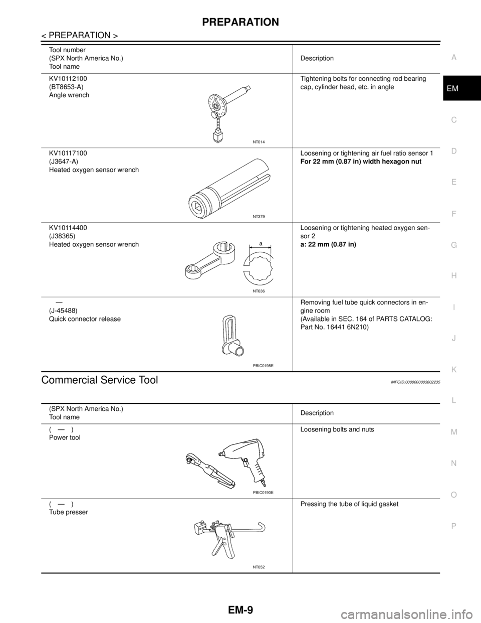
Commercial Service ToolINFOID:0000000003802235
KV10112100
(BT8653-A)
Angle wrenchTightening bolts for connecting rod bearing
cap, cylinder head, etc. in angle
KV10117100
(J3647-A)
Heated oxygen sensor wrenchLoosening or tightening air fuel ratio sensor 1
For 22 mm (0.87 in) width hexagon nut
KV10114400
(J38365)
Heated oxygen sensor wrenchLoosening or tightening heated oxygen sen-
sor 2
a: 22 mm (0.87 in)
—
(J-45488)
Quick connector releaseRemoving fuel tube quick connectors in en-
gine room
(Available in SEC. 164 of PARTS CATALOG:
Part No. 16441 6N210) Tool number
(SPX North America No.)
Tool nameDescription
NT014
NT379
NT636
PBIC0198E
(SPX North America No.)
Tool nameDescription
(—)
Power toolLoosening bolts and nuts
(—)
Tube presserPressing the tube of liquid gasket
PBIC0190E
NT052
Page 1919 of 5121
EM-44
< ON-VEHICLE REPAIR >
FUEL INJECTOR AND FUEL TUBE
FUEL INJECTOR AND FUEL TUBE
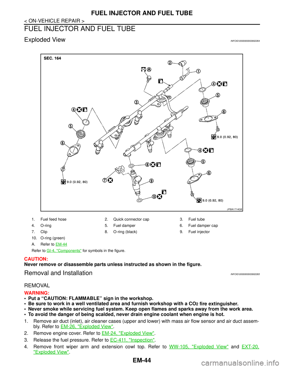
Exploded ViewINFOID:0000000003802264
CAUTION:
Never remove or disassemble parts unless instructed as shown in the figure.
Removal and InstallationINFOID:0000000003802265
REMOVAL
WARNING:
Put a “CAUTION: FLAMMABLE” sign in the workshop.
Be sure to work in a well ventilated area and furnish workshop with a CO
2 fire extinguisher.
Never smoke while servicing fuel system. Keep open flames and sparks away from the work area.
To avoid the danger of being scalded, never drain engine coolant when engine is hot.
1. Remove air duct (inlet), air cleaner cases (upper and lower) with mass air flow sensor and air duct assem-
bly. Refer to EM-26, "
Exploded View".
2. Remove engine cover. Refer to EM-24, "
Exploded View".
3. Release the fuel pressure. Refer to EC-411, "
Inspection".
4. Remove front wiper arm and extension cowl top. Refer to WW-105, "
Exploded View" and EXT-20,
"Exploded View".
1. Fuel feed hose 2. Quick connector cap 3. Fuel tube
4. O-ring 5. Fuel damper 6. Fuel damper cap
7. Clip 8. O-ring (black) 9. Fuel injector
10. O-ring (green)
A. Refer to EM-44
Refer to GI-4, "Components" for symbols in the figure.
JPBIA1714GB