2008 NISSAN LATIO coolant
[x] Cancel search: coolantPage 1359 of 2771

DTC P0300 - P0304 MULTIPLE CYLINDER MISFIRE, NO. 1 - 4 CYLINDER MIS-
FIRE
EC-285
< SERVICE INFORMATION >
C
D
E
F
G
H
I
J
K
L
MA
EC
N
P O
1. Turn ignition switch ON and select “DATA MONITOR” mode with
CONSULT-II.
2. Start engine and warm it up to normal operating temperature.
3. Turn ignition switch OFF and wait at least 10 seconds.
4. Restart engine and let it idle for about 15 minutes.
5. If 1st trip DTC is detected, go to EC-285, "
Diagnosis Procedure".
NOTE:
If 1st trip DTC is not detected during above procedure, perform-
ing the following procedure is advised.
a. Turn ignition switch OFF and wait at least 10 seconds.
b. Start engine and drive the vehicle under the similar conditions to
(1st trip) Freeze Frame Data for a certain time. Refer to table below.
Hold the accelerator pedal as steady as possible.
The similar conditions to (1st trip) Freeze Frame Data means the vehicle operation that the following con-
dition should be satisfied at the same time:
The time to driving varies according to the engine speed in the freeze frame data.
Refer to the following table.
WITH GST
Follow the procedure “WITH CONSULT-II” above.
Diagnosis ProcedureINFOID:0000000001702792
1.CHECK FOR INTAKE AIR LEAK AND PCV HOSE
1. Start engine and run it at idle speed.
2. Listen for the sound of the intake air leak.
3. Check PCV hose connection.
OK or NG
OK >> GO TO 2.
NG >> Repair or replace.
2.CHECK FOR EXHAUST SYSTEM CLOGGING
Stop engine and visually check exhaust tube, three way catalyst and muffler for dents.
OK or NG
OK >> GO TO 3.
NG >> Repair or replace.
3.PERFORM POWER BALANCE TEST
With CONSULT-II
PBIB0164E
Engine speed Engine speed in the freeze frame data ± 400 rpm
Vehicle speed Vehicle speed in the freeze frame data ± 10 km/h (6 MPH)
Engine coolant temperature
(T) conditionWhen the freeze frame data shows lower than 70°C (158°F), T should be lower than 70°C (158°F)
When the freeze frame data shows higher than or equal to 70°C (158°F), T should be higher than or
equal to 70°C (158°F)
Engine speed Time
Around 1,000 rpm Approximately 10 minutes
Around 2,000 rpm Approximately 5 minutes
More than 3,000 rpm Approximately 3.5 minutes
Page 1399 of 2771

DTC P0443 EVAP CANISTER PURGE VOLUME CONTROL SOLENOID VALVE
EC-325
< SERVICE INFORMATION >
C
D
E
F
G
H
I
J
K
L
MA
EC
N
P O
DTC P0443 EVAP CANISTER PURGE VOLUME CONTROL SOLENOID
VA LV E
DescriptionINFOID:0000000001702828
SYSTEM DESCRIPTION
*1: ECM determines the start signal status by the signals of engine speed and battery voltage.
*2: This signal is sent to the ECM though CAN communication line.
This system controls flow rate of fuel vapor from the EVAP canister. The opening of the vapor by-pass pas-
sage in the EVAP canister purge volume control solenoid valve changes to control the flow rate. The EVAP
canister purge volume control solenoid valve repeats ON/OFF operation according to the signal sent from the
ECM. The opening of the valve varies for optimum engine control. The optimum value stored in the ECM is
determined by considering various engine conditions. When the engine is operating, the flow rate of fuel vapor
from the EVAP canister is regulated as the air flow changes.
COMPONENT DESCRIPTION
The EVAP canister purge volume control solenoid valve uses a ON/
OFF duty to control the flow rate of fuel vapor from the EVAP canis-
ter. The EVAP canister purge volume control solenoid valve is
moved by ON/OFF pulses from the ECM. The longer the ON pulse,
the greater the amount of fuel vapor that will flow through the valve.
CONSULT-II Reference Value in Data Monitor ModeINFOID:0000000001702829
Specification data are reference values.
Sensor Input Signal to ECMECM
functionActuator
Crankshaft position sensor (POS)
Camshaft position sensor (PHASE)Engine speed*
1
EVAP can-
ister purge
flow controlEVAP canister purge volume
control solenoid valve Mass air flow sensor Amount of intake air
Engine coolant temperature sensor Engine coolant temperature
Battery
Battery voltage*1
Throttle position sensor Throttle position
Accelerator pedal position sensor Accelerator pedal position
Air fuel ratio (A/F) sensor 1Density of oxygen in exhaust gas
(Mixture ratio feedback signal)
Fuel tank temperature sensor Fuel temperature in fuel tank
Wheel sensor
Vehicle speed*
2
PBIA9215J
MONITOR ITEM CONDITION SPECIFICATION
PURG VOL C/V• Engine: After warming up
• Shift lever: P or N (A/T, CVT),
Neutral (M/T)
• Air conditioner switch: OFF
•No loadIdle
(Accelerator pedal is not depressed
even slightly, after engine starting)0%
2,000 rpm 0 - 50%
Page 1406 of 2771

EC-332
< SERVICE INFORMATION >
DTC P0444, P0445 EVAP CANISTER PURGE VOLUME CONTROL SOLENOID
VALVE
DTC P0444, P0445 EVAP CANISTER PURGE VOLUME CONTROL SOLE-
NOID VALVE
DescriptionINFOID:0000000001702836
SYSTEM DESCRIPTION
*1: The ECM determines the start signal status by the signal of engine speed and battery voltage.
*2: This signal is sent to the ECM through CAN communication line.
This system controls flow rate of fuel vapor from the EVAP canister. The opening of the vapor by-pass pas-
sage in the EVAP canister purge volume control solenoid valve changes to control the flow rate. The EVAP
canister purge volume control solenoid valve repeats ON/OFF operation according to the signal sent from the
ECM. The opening of the valve varies for optimum engine control. The optimum value stored in the ECM is
determined by considering various engine conditions. When the engine is operating, the flow rate of fuel vapor
from the EVAP canister is regulated as the air flow changes.
COMPONENT DESCRIPTION
The EVAP canister purge volume control solenoid valve uses a ON/
OFF duty to control the flow rate of fuel vapor from the EVAP canis-
ter. The EVAP canister purge volume control solenoid valve is
moved by ON/OFF pulses from the ECM. The longer the ON pulse,
the greater the amount of fuel vapor that will flow through the valve.
CONSULT-II Reference Value in Data Monitor ModeINFOID:0000000001702837
Specification data are reference values.
Sensor Input Signal to ECM ECM function Actuator
Crankshaft position sensor (POS)
Camshaft position sensor (PHASE)Engine speed*
1
EVAP canister
purge flow
controlEVAP canister purge volume
control solenoid valve Mass air flow sensor Amount of intake air
Engine coolant temperature sensor Engine coolant temperature
Battery
Battery voltage*1
Throttle position sensor Throttle position
Accelerator pedal position sensor Accelerator pedal position
Air fuel ratio (A/F) sensor 1Density of oxygen in exhaust gas
(Mixture ratio feedback signal)
Fuel tank temperature sensor Fuel temperature in fuel tank
Wheel sensor
Vehicle speed*
2
PBIA9215J
MONITOR ITEM CONDITION SPECIFICATION
PURG VOL C/V• Engine: After warming up
• Shift lever: N (A/T, CVT),
Neutral (M/T)
• Air conditioner switch: OFF
• No loadIdle
(Accelerator pedal is not depressed
even slightly, after engine starting)0%
2,000 rpm 0 - 50%
Page 1486 of 2771

EC-412
< SERVICE INFORMATION >
DTC P1217 ENGINE OVER TEMPERATURE
DTC P1217 ENGINE OVER TEMPERATURE
System DescriptionINFOID:0000000001702929
SYSTEM DESCRIPTION
NOTE:
•If DTC P1217 is displayed with DTC U1000 or U1001, first perform the trouble diagnosis for DTC
U1000, U1001. Refer to EC-143
.
•If DTC P1217 is displayed with DTC U1010, first perform the trouble diagnosis for DTC U1010. Refer
to EC-145
.
Cooling Fan Control
*1: The ECM determines the start signal status by the signals of engine speed and battery voltage.
*2: This signal is sent to ECM through CAN communication line.
The ECM controls the cooling fan corresponding to the vehicle speed, engine coolant temperature, refrigerant
pressure, and air conditioner ON signal. The control system has 3-step control [HIGH/LOW/OFF].
Cooling Fan Operation
Models with A/C
Models without A/C
Sensor Input Signal to ECM ECM function Actuator
Crankshaft position sensor (POS)
Camshaft position sensor (PHASE)Engine speed*
1
Cooling fan
controlIPDM E/R
(Cooling fan relays) Battery
Battery voltage*
1
Wheel sensor
Vehicle speed*2
Engine coolant temperature sensor Engine coolant temperature
Air conditioner switch
Air conditioner ON signal*
2
Refrigerant pressure sensor Refrigerant pressure
PBIB2483E
PBIB3335E
Page 1487 of 2771

DTC P1217 ENGINE OVER TEMPERATURE
EC-413
< SERVICE INFORMATION >
C
D
E
F
G
H
I
J
K
L
MA
EC
N
P O Cooling Fan Relay Operation
The ECM controls cooling fan relays in the IPDM E/R through CAN communication line.
CONSULT-II Reference Value in Data Monitor ModeINFOID:0000000001702930
Specification data are reference values.
On Board Diagnosis LogicINFOID:0000000001702931
If the cooling fan or another component in the cooling system malfunctions, engine coolant temperature will
rise. When the engine coolant temperature reaches an abnormally high temperature condition, a malfunction
is indicated.
This self-diagnosis has the one trip detection logic.
CAUTION:
When a malfunction is indicated, be sure to replace the coolant. Refer to CO-8, "
Changing Engine
Coolant". Also, replace the engine oil. Refer to LU-7, "Changing Engine Oil".
1. Fill radiator with coolant up to specified level with a filling speed of 2 liters per minute. Be sure to
use coolant with the proper mixture ratio. Refer to MA-11, "
Anti-freeze Coolant Mixture Ratio".
2. After refilling coolant, run engine to ensure that no water-flow noise is emitted.
Overall Function CheckINFOID:0000000001702932
Use this procedure to check the overall function of the cooling fan. During this check, a DTC might not be con-
firmed.
WARNING:
Cooling fan speedCooling fan relay
123
Stop (OFF) OFF OFF OFF
Low (LOW) ON OFF OFF
High (HI) OFF ON ON
MONITOR ITEM CONDITION SPECIFICATION
AIR COND SIG• Engine: After warming up, idle
the engineAir conditioner switch: OFF OFF
Air conditioner switch: ON
(Compressor operates.)ON
COOLING FAN• Engine: After warming up, idle
the engine
• Air conditioner switch: OFFEngine coolant temperature: 97°C
(207°F) or lessOFF
Engine coolant temperature: Between
98°C (208°F) and 99°C (210°F) or
moreLOW
Engine coolant temperature: 100°C
(212°F) or moreHIGH
DTC No. Trouble diagnosis name DTC detecting condition Possible cause
P1217
1217Engine over temperature
(Overheat)• Cooling fan does not operate properly (Over-
heat).
• Cooling fan system does not operate properly
(Overheat).
• Engine coolant was not added to the system
using the proper filling method.
• Engine coolant is not within the specified
range.• Harness or connectors
(Cooling fan circuit is open or shorted.)
• Cooling fan
• IPDM E/R (Cooling fan relays)
•Radiator hose
•Radiator
• Reservoir tank
•Radiator cap
• Water pump
•Thermostat
• Water control valve
For more information, refer to EC-424,
"Main 13 Causes of Overheating".
Page 1488 of 2771

EC-414
< SERVICE INFORMATION >
DTC P1217 ENGINE OVER TEMPERATURE
Never remove the radiator cap when the engine is hot. Serious burns could be caused by high pres-
sure fluid escaping from the reservoir tank or the radiator.
Wrap a thick cloth around cap. Carefully remove the cap by turning it a quarter turn to allow built-up
pressure to escape. Then turn the cap all the way off.
WITH CONSULT-II
1. Check the coolant level in the reservoir tank and radiator.
Allow engine to cool before checking coolant level.
If the coolant level in the reservoir tank and/or radiator is below
the proper range, skip the following steps and go to EC-417,
"Diagnosis Procedure" or EC-417, "Diagnosis Procedure".
2. Confirm whether customer filled the coolant or not. If customer
filled the coolant, skip the following steps and go to EC-417,
"Diagnosis Procedure" or EC-417, "Diagnosis Procedure".
3. Turn ignition switch ON.
4. Perform “COOLING FAN” in “ACTIVE TEST” mode with CON-
SULT-II.
5. If the results are NG, go to EC-417, "
Diagnosis Procedure" or
EC-417, "
Diagnosis Procedure".
WITH GST
Models with A/C
1. Check the coolant level in the reservoir tank and radiator.
Allow engine to cool before checking coolant level.
If the coolant level in the reservoir tank and/or radiator is below
the proper range, skip the following steps and go to EC-417,
"Diagnosis Procedure".
2. Confirm whether customer filled the coolant or not. If customer
filled the coolant, skip the following steps and go to EC-417,
"Diagnosis Procedure".
3. Start engine.
CAUTION:
Be careful not to overheat engine.
4. Set temperature control switch to full cold position.
5. Turn air conditioner switch ON.
6. Turn blower fan switch ON.
7. Run engine at idle for a few minutes with air conditioner operating.
CAUTION:
Be careful not to overheat engine.
SEF621W
SEF646X
SEF621W
Page 1489 of 2771
DTC P1217 ENGINE OVER TEMPERATURE
EC-415
< SERVICE INFORMATION >
C
D
E
F
G
H
I
J
K
L
MA
EC
N
P O
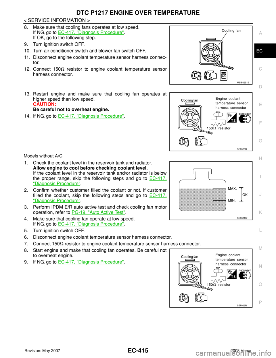
8. Make sure that cooling fans operates at low speed.
If NG, go to EC-417, "
Diagnosis Procedure".
If OK, go to the following step.
9. Turn ignition switch OFF.
10. Turn air conditioner switch and blower fan switch OFF.
11. Disconnect engine coolant temperature sensor harness connec-
tor.
12. Connect 150Ω resistor to engine coolant temperature sensor
harness connector.
13. Restart engine and make sure that cooling fan operates at
higher speed than low speed.
CAUTION:
Be careful not to overheat engine.
14. If NG, go to EC-417, "
Diagnosis Procedure".
Models without A/C
1. Check the coolant level in the reservoir tank and radiator.
Allow engine to cool before checking coolant level.
If the coolant level in the reservoir tank and/or radiator is below
the proper range, skip the following steps and go to EC-417,
"Diagnosis Procedure".
2. Confirm whether customer filled the coolant or not. If customer
filled the coolant, skip the following steps and go to EC-417,
"Diagnosis Procedure".
3. Perform IPDM E/R auto active test and check cooling fan motor
operation, refer to PG-19, "
Auto Active Test".
4. Make sure that cooling fan operate at low speed.
If NG, go to EC-417, "
Diagnosis Procedure".
5. Turn ignition switch OFF.
6. Disconnect engine coolant temperature sensor harness connector.
7. Connect 150Ω resistor to engine coolant temperature sensor harness connector.
8. Start engine and make that cooling fan operates. Be careful not
to overheat engine.
9. If NG, go to EC-417, "
Diagnosis Procedure".
MBIB0651E
SEF023R
SEF621W
SEF023R
Page 1492 of 2771

EC-418
< SERVICE INFORMATION >
DTC P1217 ENGINE OVER TEMPERATURE
No >> GO TO 4.
2.CHECK COOLING FAN LOW SPEED OPERATION
With CONSULT-II
1. Turn ignition switch ON.
2. Perform “COOLING FAN” in “ACTIVE TEST” mode with CON-
SULT-II and touch “LOW” on the CONSULT-II screen.
3. Make sure that cooling fan operate at low speed.
OK or NG
OK >> GO TO 3.
NG >> Check cooling fan control circuit. (Go to "PROCEDURE
A".)
3.CHECK COOLING FAN HIGH SPEED OPERATION
With CONSULT-II
1. Touch “HIGH” on the CONSULT-II screen.
2. Make sure that cooling fan operate at higher speed than low
speed.
OK or NG
OK >> GO TO 6.
NG >> Check cooling fan control circuit. (Go to "PROCEDURE
A".)
4.CHECK COOLING FAN LOW SPEED OPERATION
Without CONSULT-II
1. Start engine and let it idle.
2. Turn air conditioner switch ON.
3. Turn blower fan switch ON.
4. Make sure that cooling fan operate at low speed.
OK or NG
OK >> GO TO 5.
NG >> Check cooling fan low speed control circuit. (Go to
"PROCEDURE A".)
5.CHECK COOLING FAN HIGH SPEED OPERATION
Without CONSULT-II
1. Turn ignition switch OFF.
2. Turn air conditioner switch and blower fan switch OFF.
3. Disconnect engine coolant temperature sensor harness connector.
4. Connect 150Ω resistor to engine coolant temperature sensor harness connector.
SEF784Z
SEF785Z
MBIB0651E