2008 NISSAN LATIO wiring diagram
[x] Cancel search: wiring diagramPage 647 of 2771
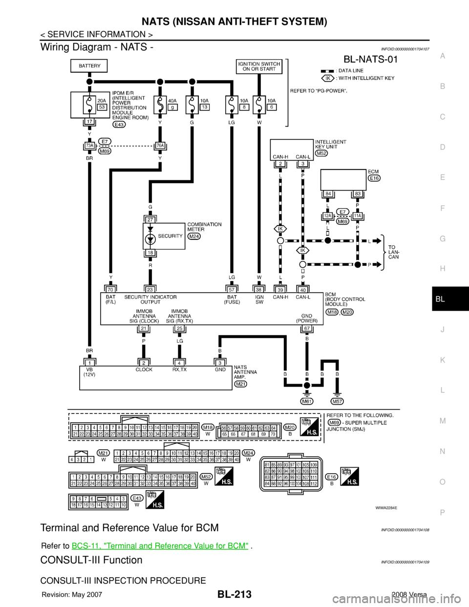
NATS (NISSAN ANTI-THEFT SYSTEM)
BL-213
< SERVICE INFORMATION >
C
D
E
F
G
H
J
K
L
MA
B
BL
N
O
P
Wiring Diagram - NATS -INFOID:0000000001704107
Terminal and Reference Value for BCMINFOID:0000000001704108
Refer to BCS-11, "Terminal and Reference Value for BCM" .
CONSULT-III FunctionINFOID:0000000001704109
CONSULT-III INSPECTION PROCEDURE
WIWA2284E
Page 766 of 2771
BRC-1
BRAKES
C
D
E
G
H
I
J
K
L
M
SECTION BRC
A
B
BRC
N
O
P
CONTENTS
BRAKE CONTROL SYSTEM
ABS
SERVICE INFORMATION ............................
2
PRECAUTIONS ...................................................2
Precaution for Supplemental Restraint System
(SRS) "AIR BAG" and "SEAT BELT PRE-TEN-
SIONER" ...................................................................
2
Precaution for Brake System ....................................2
Precaution for Brake Control .....................................2
Precaution for CAN System ......................................3
PREPARATION ...................................................4
Special Service Tool .................................................4
Commercial Service Tool ..........................................4
SYSTEM DESCRIPTION .....................................5
System Component ...................................................5
ABS Function ............................................................5
EBD Function ............................................................5
Fail-Safe Function .....................................................5
Hydraulic Circuit Diagram .........................................6
CAN COMMUNICATION .....................................7
System Description ...................................................7
TROUBLE DIAGNOSIS ......................................8
How to Perform Trouble Diagnosis for Quick and
Accurate Repair ........................................................
8
Component Parts and Harness Connector Loca-
tion ..........................................................................
11
Schematic ...............................................................12
Wiring Diagram - ABS - ...........................................13
Basic Inspection ......................................................16
Warning Lamp and Indicator Timing ........................17
Control Unit Input/Output Signal Standard ..............17
CONSULT-III Function (ABS) ..................................18
TROUBLE DIAGNOSIS FOR SELF-DIAG-
NOSTIC ITEMS .................................................
24
Wheel Sensor System .............................................24
ABS Control Unit Inspection ....................................25
Solenoid Valve System Inspection ..........................25
Actuator Motor, Motor Relay, and Circuit Inspec-
tion ...........................................................................
26
ABS Control Unit Power and Ground Systems In-
spection ...................................................................
27
CAN Communication System Inspection .................28
TROUBLE DIAGNOSES FOR SYMPTOMS .....29
ABS Works Frequently ............................................29
Unexpected Pedal Action ........................................29
Long Stopping Distance ..........................................30
ABS Does Not Work ................................................30
Pedal Vibration or ABS Operation Noise .................30
WHEEL SENSORS ...........................................32
Removal and Installation .........................................32
SENSOR ROTOR ..............................................34
Removal and Installation .........................................34
ACTUATOR AND ELECTRIC UNIT (ASSEM-
BLY) ..................................................................
35
Removal and Installation .........................................35
Page 778 of 2771
![NISSAN LATIO 2008 Service Repair Manual TROUBLE DIAGNOSIS
BRC-13
< SERVICE INFORMATION >[ABS]
C
D
E
G
H
I
J
K
L
MA
B
BRC
N
O
P
Wiring Diagram - ABS -INFOID:0000000001703834
WFWA0419E NISSAN LATIO 2008 Service Repair Manual TROUBLE DIAGNOSIS
BRC-13
< SERVICE INFORMATION >[ABS]
C
D
E
G
H
I
J
K
L
MA
B
BRC
N
O
P
Wiring Diagram - ABS -INFOID:0000000001703834
WFWA0419E](/manual-img/5/57360/w960_57360-777.png)
TROUBLE DIAGNOSIS
BRC-13
< SERVICE INFORMATION >[ABS]
C
D
E
G
H
I
J
K
L
MA
B
BRC
N
O
P
Wiring Diagram - ABS -INFOID:0000000001703834
WFWA0419E
Page 840 of 2771
CVT-1
TRANSMISSION/TRANSAXLE
D
E
F
G
H
I
J
K
L
M
SECTION CVT
A
B
CVT
N
O
P
CONTENTS
CVT
SERVICE INFORMATION ............................5
INDEX FOR DTC .................................................5
Alphabetical Index .....................................................5
DTC No. Index ..........................................................5
PRECAUTIONS ...................................................7
Precaution for Supplemental Restraint System
(SRS) "AIR BAG" and "SEAT BELT PRE-TEN-
SIONER" ...................................................................
7
Precaution Necessary for Steering Wheel Rota-
tion After Battery Disconnect .....................................
7
Precaution for On Board Diagnosis (OBD) System
of CVT and Engine ....................................................
7
Service After Replacing TCM and Transaxle As-
sembly .......................................................................
8
Removal and Installation Procedure for CVT Unit
Connector ..................................................................
9
Precaution ...............................................................10
Service Notice or Precaution ...................................11
PREPARATION ..................................................12
Special Service Tool ...............................................12
Commercial Service Tool ........................................12
CVT FLUID .........................................................13
Checking CVT Fluid ................................................13
Changing CVT Fluid ................................................14
CVT Fluid Cooler Cleaning .....................................14
CVT SYSTEM .....................................................18
Cross-Sectional View - RE0F08A ...........................18
Control System ........................................................19
Hydraulic Control System ........................................20
TCM Function ..........................................................20
CAN Communication ...............................................21
Input/Output Signal of TCM .....................................22
Line Pressure and Secondary Pressure Control .....22
Shift Control ............................................................23
Lock-up and Select Control .....................................24
Control Valve ...........................................................25
ON BOARD DIAGNOSTIC (OBD) SYSTEM ....26
Introduction ..............................................................26
OBD-II Function for CVT System ............................26
One or Two Trip Detection Logic of OBD-II .............26
OBD-II Diagnostic Trouble Code (DTC) ..................26
Malfunction Indicator Lamp (MIL) ............................27
TROUBLE DIAGNOSIS ....................................29
DTC Inspection Priority Chart ..................................29
Fail-Safe ..................................................................29
How to Perform Trouble Diagnosis for Quick and
Accurate Repair .......................................................
30
CVT Electrical Parts Location ..................................35
Circuit Diagram ........................................................36
Inspections before Trouble Diagnosis .....................36
Road Test ................................................................40
Check before Engine Is Started ...............................41
Check at Idle ............................................................41
Cruise Test ..............................................................43
Vehicle Speed When Shifting Gears .......................45
TCM Terminal and Reference Value .......................45
CONSULT-III Function (TRANSMISSION) ..............47
Diagnosis Procedure without CONSULT-III ............55
DTC U1000 CAN COMMUNICATION LINE .....56
Description ...............................................................56
On Board Diagnosis Logic .......................................56
Possible Cause ........................................................56
DTC Confirmation Procedure ..................................56
Wiring Diagram - CVT - CAN ...................................57
Diagnosis Procedure ...............................................58
DTC U1010 TRANSMISSION CONTROL
MODULE (CAN) ................................................
59
Description ...............................................................59
On Board Diagnosis Logic .......................................59
Possible Cause ........................................................59
DTC Confirmation Procedure ..................................59
Diagnosis Procedure ...............................................59
DTC P0615 START SIGNAL CIRCUIT .............60
Page 841 of 2771

CVT-2
Description ..............................................................60
CONSULT-III Reference Value in Data Monitor
Mode .......................................................................
60
On Board Diagnosis Logic ......................................60
Possible Cause .......................................................60
DTC Confirmation Procedure .................................60
Wiring Diagram - CVT - STSIG ...............................61
Diagnosis Procedure ..............................................62
DTC P0703 STOP LAMP SWITCH CIRCUIT ....63
Description ..............................................................63
CONSULT-III Reference Value in Data Monitor
Mode .......................................................................
63
On Board Diagnosis Logic ......................................63
Possible Cause .......................................................63
DTC Confirmation Procedure .................................63
Diagnosis Procedure ..............................................63
DTC P0705 PARK/NEUTRAL POSITION
SWITCH .............................................................
65
Description ..............................................................65
CONSULT-III Reference Value in Data Monitor
Mode .......................................................................
65
On Board Diagnosis Logic ......................................65
Possible Cause .......................................................65
DTC Confirmation Procedure .................................65
Wiring Diagram - CVT - PNP/SW ...........................67
Diagnosis Procedure ..............................................68
Component Inspection ............................................70
DTC P0710 CVT FLUID TEMPERATURE
SENSOR CIRCUIT .............................................
71
Description ..............................................................71
CONSULT-III Reference Value in Data Monitor
Mode .......................................................................
71
On Board Diagnosis Logic ......................................71
Possible Cause .......................................................71
DTC Confirmation Procedure .................................71
Wiring Diagram - CVT - FTS ...................................72
Diagnosis Procedure ..............................................73
Component Inspection ............................................74
DTC P0715 INPUT SPEED SENSOR CIR-
CUIT (PRI SPEED SENSOR) ............................
76
Description ..............................................................76
CONSULT-III Reference Value in Data Monitor
Mode .......................................................................
76
On Board Diagnosis Logic ......................................76
Possible Cause .......................................................76
DTC Confirmation Procedure .................................76
Wiring Diagram - CVT - PRSCVT ...........................77
Diagnosis Procedure ..............................................78
DTC P0720 VEHICLE SPEED SENSOR CVT
(SECONDARY SPEED SENSOR) .....................
80
Description ..............................................................80
CONSULT-III Reference Value in Data Monitor
Mode .......................................................................
80
On Board Diagnosis Logic ......................................80
Possible Cause .......................................................80
DTC Confirmation Procedure ..................................80
Wiring Diagram - CVT - SESCVT ...........................81
Diagnosis Procedure ...............................................82
DTC P0725 ENGINE SPEED SIGNAL ..............85
Description ..............................................................85
CONSULT-III Reference Value in Data Monitor
Mode .......................................................................
85
On Board Diagnosis Logic ......................................85
Possible Cause .......................................................85
DTC Confirmation Procedure ..................................85
Diagnosis Procedure ...............................................85
DTC P0730 BELT DAMAGE .............................87
Description ..............................................................87
CONSULT-III Reference Value in Data Monitor
Mode .......................................................................
87
On Board Diagnosis Logic ......................................87
Possible Cause .......................................................87
DTC Confirmation Procedure ..................................87
Diagnosis Procedure ...............................................87
DTC P0740 TORQUE CONVERTER CLUTCH
SOLENOID VALVE ...........................................
88
Description ..............................................................88
CONSULT-III Reference Value in Data Monitor
Mode .......................................................................
88
On Board Diagnosis Logic ......................................88
Possible Cause .......................................................88
DTC Confirmation Procedure ..................................88
Wiring Diagram - CVT - TCV ..................................89
Diagnosis Procedure ...............................................90
Component Inspection ............................................91
DTC P0744 A/T TCC S/V FUNCTION (LOCK-
UP) .....................................................................
93
Description ..............................................................93
CONSULT-III Reference Value in Data Monitor
Mode .......................................................................
93
On Board Diagnosis Logic ......................................93
Possible Cause .......................................................93
DTC Confirmation Procedure ..................................93
Diagnosis Procedure ...............................................93
DTC P0745 LINE PRESSURE SOLENOID
VALVE ...............................................................
95
Description ..............................................................95
CONSULT-III Reference Value in Data Monitor
Mode .......................................................................
95
On Board Diagnosis Logic ......................................95
Possible Cause .......................................................95
DTC Confirmation Procedure ..................................95
Wiring Diagram - CVT - LPSV ................................96
Diagnosis Procedure ...............................................97
Component Inspection ............................................98
DTC P0746 PRESSURE CONTROL SOLE-
NOID A PERFORMANCE (LINE PRESSURE
SOLENOID VALVE) .........................................
100
Description ............................................................100
Page 842 of 2771
CVT-3
D
E
F
G
H
I
J
K
L
MA
B
CVT
N
O
P N CONSULT-III Reference Value in Data Monitor
Mode .....................................................................
100
On Board Diagnosis Logic ....................................100
Possible Cause .....................................................100
DTC Confirmation Procedure ................................100
Diagnosis Procedure .............................................100
DTC P0776 PRESSURE CONTROL SOLE-
NOID B PERFORMANCE (SEC PRESSURE
SOLENOID VALVE) .........................................
102
Description ............................................................102
CONSULT-III Reference Value in Data Monitor
Mode .....................................................................
102
On Board Diagnosis Logic ....................................102
Possible Cause .....................................................102
DTC Confirmation Procedure ................................102
Diagnosis Procedure .............................................102
DTC P0778 PRESSURE CONTROL SOLE-
NOID B ELECTRICAL (SEC PRESSURE SO-
LENOID VALVE) ..............................................
104
Description ............................................................104
CONSULT-III Reference Value in Data Monitor
Mode .....................................................................
104
On Board Diagnosis Logic ....................................104
Possible Cause .....................................................104
DTC Confirmation Procedure ................................104
Wiring Diagram - CVT - SECPSV .........................105
Diagnosis Procedure .............................................106
Component Inspection ..........................................107
DTC P0840 TRANSMISSION FLUID PRES-
SURE SENSOR A CIRCUIT (SEC PRES-
SURE SENSOR) ...............................................
109
Description ............................................................109
CONSULT-III Reference Value in Data Monitor
Mode .....................................................................
109
On Board Diagnosis Logic ....................................109
Possible Cause .....................................................109
DTC Confirmation Procedure ................................109
Wiring Diagram - CVT - SECPS ............................110
Diagnosis Procedure .............................................111
DTC P0841 PRESSURE SENSOR FUNC-
TION .................................................................
113
Description ............................................................113
CONSULT-III Reference Value in Data Monitor
Mode .....................................................................
113
On Board Diagnosis Logic ....................................113
Possible Cause .....................................................113
DTC Confirmation Procedure ................................113
Diagnosis Procedure .............................................113
DTC P0845 TRANSMISSION FLUID PRES-
SURE SENSOR B CIRCUIT (PRI PRESSURE
SENSOR) ..........................................................
115
Description ............................................................115
CONSULT-III Reference Value in Data Monitor
Mode .....................................................................
115
On Board Diagnosis Logic .....................................115
Possible Cause ......................................................115
DTC Confirmation Procedure ................................115
Wiring Diagram - CVT - PRIPS .............................116
Diagnosis Procedure .............................................117
DTC P0868 SECONDARY PRESSURE
DOWN .............................................................
119
Description .............................................................119
CONSULT-III Reference Value in Data Monitor
Mode ......................................................................
119
On Board Diagnosis Logic .....................................119
Possible Cause ......................................................119
DTC Confirmation Procedure ................................119
Diagnosis Procedure .............................................119
DTC P1701 TRANSMISSION CONTROL
MODULE (POWER SUPPLY) .........................
121
Description .............................................................121
On Board Diagnosis Logic .....................................121
Possible Cause ......................................................121
DTC Confirmation Procedure ................................121
Wiring Diagram - CVT - POWER ...........................122
Diagnosis Procedure .............................................123
DTC P1705 THROTTLE POSITION SENSOR .125
Description .............................................................125
CONSULT-III Reference Value in Data Monitor
Mode ......................................................................
125
On Board Diagnosis Logic .....................................125
Possible Cause ......................................................125
DTC Confirmation Procedure ................................125
Diagnosis Procedure .............................................125
DTC P1722 ESTM VEHICLE SPEED SIGNAL .127
Description .............................................................127
CONSULT-III Reference Value in Data Monitor
Mode ......................................................................
127
On Board Diagnosis Logic .....................................127
Possible Cause ......................................................127
DTC Confirmation Procedure ................................127
Diagnosis Procedure .............................................127
DTC P1723 CVT SPEED SENSOR FUNC-
TION ................................................................
129
Description .............................................................129
On Board Diagnosis Logic .....................................129
Possible Cause ......................................................129
DTC Confirmation Procedure ................................129
Diagnosis Procedure .............................................129
DTC P1726 ELECTRIC THROTTLE CON-
TROL SYSTEM ...............................................
131
Description .............................................................131
On Board Diagnosis Logic .....................................131
Possible Cause ......................................................131
DTC Confirmation Procedure ................................131
Diagnosis Procedure .............................................131
Page 843 of 2771

CVT-4
DTC P1740 LOCK-UP SELECT SOLENOID
VALVE CIRCUIT ..............................................
132
Description .............................................................132
CONSULT-III Reference Value in Data Monitor
Mode ......................................................................
132
On Board Diagnosis Logic .....................................132
Possible Cause ......................................................132
DTC Confirmation Procedure ................................132
Wiring Diagram - CVT - L/USSV ............................133
Diagnosis Procedure .............................................134
Component Inspection ...........................................135
DTC P1745 LINE PRESSURE CONTROL ......136
Description .............................................................136
On Board Diagnosis Logic .....................................136
Possible Cause ......................................................136
DTC Confirmation Procedure ................................136
Diagnosis Procedure .............................................136
DTC P1777 STEP MOTOR - CIRCUIT ............137
Description .............................................................137
CONSULT-III Reference Value in Data Monitor
Mode ......................................................................
137
On Board Diagnosis Logic .....................................137
Possible Cause ......................................................137
DTC Confirmation Procedure ................................137
Wiring Diagram - CVT - STM .................................138
Diagnosis Procedure .............................................139
Component Inspection ...........................................140
DTC P1778 STEP MOTOR - FUNCTION ........141
Description .............................................................141
CONSULT-III Reference Value in Data Monitor
Mode ......................................................................
141
On Board Diagnosis Logic .....................................141
Possible Cause ......................................................141
DTC Confirmation Procedure ................................141
Diagnosis Procedure .............................................142
OVERDRIVE CONTROL SWITCH ..................143
Description .............................................................143
CONSULT-III Reference Value in Data Monitor
Mode ......................................................................
143
Wiring Diagram - CVT - ODSW .............................144
Diagnosis Procedure .............................................144
Component Inspection ...........................................146
SHIFT POSITION INDICATOR CIRCUIT ........148
Description .............................................................148
CONSULT-III Reference Value in Data Monitor
Mode ......................................................................
148
Diagnosis Procedure .............................................148
TROUBLE DIAGNOSIS FOR SYMPTOMS .....149
Wiring Diagram - CVT - NONDTC .........................149
O/D OFF Indicator Lamp Does Not Come On ......151
Engine Cannot Be Started in "P" and "N" Position .153
In "P" Position, Vehicle Moves Forward or Back-
ward When Pushed ...............................................
153
In "N" Position, Vehicle Moves ..............................154
Large Shock "N" → "R" Position ...........................154
Vehicle Does Not Creep Backward in "R" Position .155
Vehicle Does Not Creep Forward in "D" or "L" Po-
sition ......................................................................
156
Vehicle Speed Does Not Change in "L" Position ..157
Vehicle Speed Does Not Change in overdrive-off
mode .....................................................................
158
Vehicle Speed Does Not Change in "D" Position .159
Vehicle Does Not Decelerate by Engine Brake ....159
TRANSMISSION CONTROL MODULE ...........161
Removal and Installation .......................................161
CVT SHIFT LOCK SYSTEM .............................162
Description ............................................................162
Shift Lock System Electrical Parts Location ..........162
Wiring Diagram - CVT - SHIFT .............................163
Diagnosis Procedure .............................................163
SHIFT CONTROL SYSTEM .............................167
Removal and Installation .......................................167
Control Device Disassembly and Assembly .........170
Selector Lever Knob Removal and Installation .....170
Adjustment of CVT Position ..................................171
Checking of CVT Position .....................................171
KEY INTERLOCK CABLE ...............................173
Removal and Installation .......................................173
AIR BREATHER HOSE ....................................176
Removal and Installation .......................................176
DIFFERENTIAL SIDE OIL SEAL .....................177
Removal and Installation .......................................177
TRANSAXLE ASSEMBLY ...............................178
Removal and Installation .......................................178
SERVICE DATA AND SPECIFICATIONS
(SDS) ................................................................
181
General Specification ............................................181
Vehicle Speed When Shifting Gears .....................181
Stall Speed ............................................................181
Line Pressure ........................................................181
Solenoid Valves ....................................................182
CVT Fluid Temperature Sensor ............................182
Primary Speed Sensor ..........................................182
Secondary Speed Sensor .....................................182
Removal and Installation .......................................182
Page 860 of 2771
CVT SYSTEM
CVT-21
< SERVICE INFORMATION >
D
E
F
G
H
I
J
K
L
MA
B
CVT
N
O
P
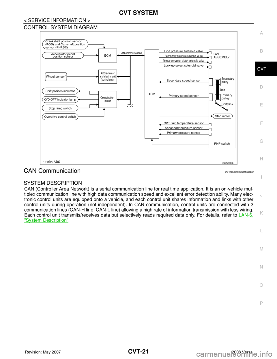
CONTROL SYSTEM DIAGRAM
CAN CommunicationINFOID:0000000001703440
SYSTEM DESCRIPTION
CAN (Controller Area Network) is a serial communication line for real time application. It is an on-vehicle mul-
tiplex communication line with high data communication speed and excellent error detection ability. Many elec-
tronic control units are equipped onto a vehicle, and each control unit shares information and links with other
control units during operation (not independent). In CAN communication, control units are connected with 2
communication lines (CAN-H line, CAN-L line) allowing a high rate of information transmission with less wiring.
Each control unit transmits/receives data but selectively reads required data only. For details, refer to LAN-6,
"System Description".
SCIA7933E