2008 NISSAN LATIO service interval
[x] Cancel search: service intervalPage 2267 of 2771
![NISSAN LATIO 2008 Service Repair Manual PERIODIC MAINTENANCE
MA-7
< SERVICE INFORMATION >
C
D
E
F
G
H
I
J
K
MA
B
MA
N
O
P
Abbreviations: R = Replace. I = Inspect. Correct or replace if necessary. [ ]: At the mileage intervals only
(1) After NISSAN LATIO 2008 Service Repair Manual PERIODIC MAINTENANCE
MA-7
< SERVICE INFORMATION >
C
D
E
F
G
H
I
J
K
MA
B
MA
N
O
P
Abbreviations: R = Replace. I = Inspect. Correct or replace if necessary. [ ]: At the mileage intervals only
(1) After](/manual-img/5/57360/w960_57360-2266.png)
PERIODIC MAINTENANCE
MA-7
< SERVICE INFORMATION >
C
D
E
F
G
H
I
J
K
MA
B
MA
N
O
P
Abbreviations: R = Replace. I = Inspect. Correct or replace if necessary. [ ]: At the mileage intervals only
(1) After 60,000 miles (96,000 km) or 48 months, inspect every 15,000 miles (24,000 km) or 12 months. Replace the drive belts if found
damaged.
(2) If operating mainly in dusty conditions, more frequent maintenance may be required.
(3) Maintenance-free item. For service procedures, go to the FL section.
(4) After 60,000 miles (96,000 km) or 48 months, replace every 30,000 miles (48,000 km) or 24 months.
(5) If valve noise increases, inspect valve clearance.
* Maintenance items and intervals with “*” are recommended by NISSAN for reliable vehicle operation. The owner need not perform
such maintenance in order to maintain the emission warranty or manufacturer recall liability. Other maintenance items and intervals are
required.
Chassis and Body Maintenance
Abbreviations: R = Replace. I = Inspect. Correct or replace if necessary. L = Lubricate.
MAINTENANCE OPERATIONMAINTENANCE INTERVAL
Reference Section -
Page or - Content Title Perform at number of
miles, kilometers or
months, whichever
comes first.Miles x
1,000
(km x
1,000)
Months33.75
(54)
2737.5
(60)
3041.25
(66)
3345
(72)
3648.75
(78)
3952.5
(84)
4256.25
(90)
4560
(96)
48
Drive beltNOTE
(1)I*MA-12
Air cleaner filterNOTE
(2)[R]MA-14
EVAP vapor linesI*MA-18
Fuel linesI*MA-14
Fuel filterNOTE
(3)—
Engine coolantNOTE
(4)R*MA-12
Engine oil R R R R R R R RMA-15
Engine oil filter (Use
genuine oil filter or
equivalent)R R R R RRRRMA-16
Spark plugs (Iridium/
platinum-tipped type)Replace every 105,000 miles (169,000 km)MA-17
Intake and exhaust
valve clearance NOTE
(5)EM-104
MAINTENANCE OPERATIONMAINTENANCE INTERVAL
Reference
Section -
Page or -
Content Title Perform at number of
miles, kilometers or
months, whichever
comes first.Miles x
1,000
(km x
1,000)
Months3.75
(6)
37.5
(12)
611 . 2 5
(18)
915
(24)
1218.75
(30)
1522.5
(36)
1826.25
(42)
2130
(48)
24
Brake lines & cables I IMA-24
Brake pads, rotors,
drums & liningsIIIIMA-24
Manual transaxle oil or
automatic transaxle
fluidNOTE (1) I IMA-19 , MA-
22 or MA-21
CVT fluid NOTE (2) I I
Steering gear & link-
age, axle & suspen-
sion partsIIIIMA-25
, PS-
12
Tire rotation NOTE (3)WT-6
Front drive shaft boots I I I IMA-26
Page 2268 of 2771
MA-8
< SERVICE INFORMATION >
PERIODIC MAINTENANCE
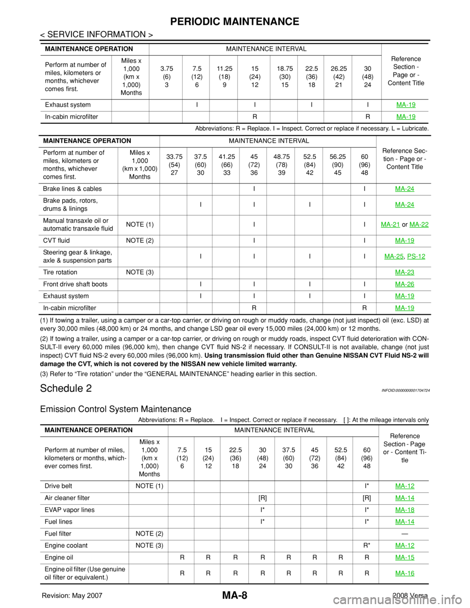
Abbreviations: R = Replace. I = Inspect. Correct or replace if necessary. L = Lubricate.
(1) If towing a trailer, using a camper or a car-top carrier, or driving on rough or muddy roads, change (not just inspect) oil (exc. LSD) at
every 30,000 miles (48,000 km) or 24 months, and change LSD gear oil every 15,000 miles (24,000 km) or 12 months.
(2) If towing a trailer, using a camper or a car-top carrier, or driving on rough or muddy roads, inspect CVT fluid deterioration with CON-
SULT-II every 60,000 miles (96,000 km), then change CVT fluid NS-2 if necessary. If CONSULT-II is not available, change (not just
inspect) CVT fluid NS-2 every 60,000 miles (96,000 km). Using transmission fluid other than Genuine NISSAN CVT Fluid NS-2 will
damage the CVT, which is not covered by the NISSAN new vehicle limited warranty.
(3) Refer to “Tire rotation” under the “GENERAL MAINTENANCE” heading earlier in this section.
Schedule 2INFOID:0000000001704724
Emission Control System Maintenance
Abbreviations: R = Replace. I = Inspect. Correct or replace if necessary. [ ]: At the mileage intervals only
Exhaust system I I I IMA-19
In-cabin microfilter R RMA-19
MAINTENANCE OPERATIONMAINTENANCE INTERVAL
Reference
Section -
Page or -
Content Title Perform at number of
miles, kilometers or
months, whichever
comes first.Miles x
1,000
(km x
1,000)
Months3.75
(6)
37.5
(12)
611 . 2 5
(18)
915
(24)
1218.75
(30)
1522.5
(36)
1826.25
(42)
2130
(48)
24
MAINTENANCE OPERATIONMAINTENANCE INTERVAL
Reference Sec-
tion - Page or -
Content Title Perform at number of
miles, kilometers or
months, whichever
comes first.Miles x
1,000
(km x 1,000)
Months33.75
(54)
2737.5
(60)
3041.25
(66)
3345
(72)
3648.75
(78)
3952.5
(84)
4256.25
(90)
4560
(96)
48
Brake lines & cables I IMA-24
Brake pads, rotors,
drums & liningsII I IMA-24
Manual transaxle oil or
automatic transaxle fluidNOTE (1) I IMA-21 or MA-22
CVT fluid NOTE (2) I IMA-19
Steering gear & linkage,
axle & suspension partsII I IMA-25, PS-12
Tire rotation NOTE (3)MA-23
Front drive shaft boots I I I IMA-26
Exhaust system I I I IMA-19
In-cabin microfilter R RMA-19
MAINTENANCE OPERATIONMAINTENANCE INTERVAL
Reference
Section - Page
or - Content Ti-
tle Perform at number of miles,
kilometers or months, which-
ever comes first.Miles x
1,000
(km x
1,000)
Months7.5
(12)
615
(24)
1222.5
(36)
1830
(48)
2437.5
(60)
3045
(72)
3652.5
(84)
4260
(96)
48
Drive belt NOTE (1) I*MA-12
Air cleaner filter [R] [R]MA-14
EVAP vapor lines I* I*MA-18
Fuel lines I* I*MA-14
Fuel filter NOTE (2)—
Engine coolant NOTE (3) R*MA-12
Engine oil RR R RRRRRMA-15
Engine oil filter (Use genuine
oil filter or equivalent.)RR R RRRRRMA-16
Page 2269 of 2771
PERIODIC MAINTENANCE
MA-9
< SERVICE INFORMATION >
C
D
E
F
G
H
I
J
K
MA
B
MA
N
O
P
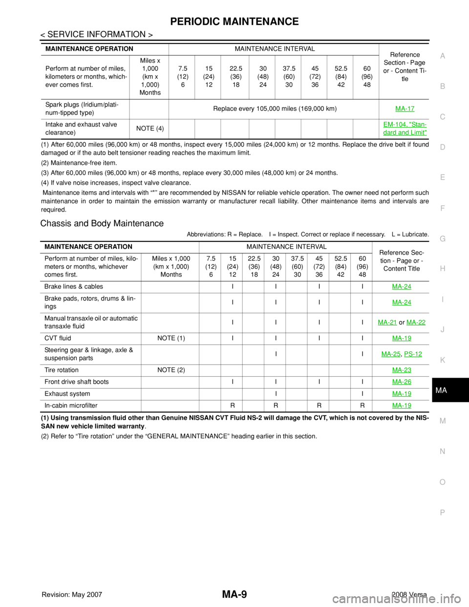
(1) After 60,000 miles (96,000 km) or 48 months, inspect every 15,000 miles (24,000 km) or 12 months. Replace the drive belt if found
damaged or if the auto belt tensioner reading reaches the maximum limit.
(2) Maintenance-free item.
(3) After 60,000 miles (96,000 km) or 48 months, replace every 30,000 miles (48,000 km) or 24 months.
(4) If valve noise increases, inspect valve clearance.
Maintenance items and intervals with “*” are recommended by NISSAN for reliable vehicle operation. The owner need not perform such
maintenance in order to maintain the emission warranty or manufacturer recall liability. Other maintenance items and intervals are
required.
Chassis and Body Maintenance
Abbreviations: R = Replace. I = Inspect. Correct or replace if necessary. L = Lubricate.
(1) Using transmission fluid other than Genuine NISSAN CVT Fluid NS-2 will damage the CVT, which is not covered by the NIS-
SAN new vehicle limited warranty.
(2) Refer to “Tire rotation” under the “GENERAL MAINTENANCE” heading earlier in this section. Spark plugs (Iridium/plati-
num-tipped type)Replace every 105,000 miles (169,000 km)MA-17
Intake and exhaust valve
clearance)NOTE (4)EM-104, "Sta n-
dard and Limit"
MAINTENANCE OPERATIONMAINTENANCE INTERVAL
Reference
Section - Page
or - Content Ti-
tle Perform at number of miles,
kilometers or months, which-
ever comes first.Miles x
1,000
(km x
1,000)
Months7.5
(12)
615
(24)
1222.5
(36)
1830
(48)
2437.5
(60)
3045
(72)
3652.5
(84)
4260
(96)
48
MAINTENANCE OPERATIONMAINTENANCE INTERVAL
Reference Sec-
tion - Page or -
Content Title Perform at number of miles, kilo-
meters or months, whichever
comes first.Miles x 1,000
(km x 1,000)
Months7.5
(12)
615
(24)
1222.5
(36)
1830
(48)
2437.5
(60)
3045
(72)
3652.5
(84)
4260
(96)
48
Brake lines & cables I I I IMA-24
Brake pads, rotors, drums & lin-
ings IIIIMA-24
Manual transaxle oil or automatic
transaxle fluidIIIIMA-21 or MA-22
CVT fluid NOTE (1) IIIIMA-19
Steering gear & linkage, axle &
suspension partsIIMA-25, PS-12
Tire rotation NOTE (2)MA-23
Front drive shaft boots I I I IMA-26
Exhaust system I IMA-19
In-cabin microfilter R R R RMA-19
Page 2275 of 2771
ENGINE MAINTENANCE
MA-15
< SERVICE INFORMATION >
C
D
E
F
G
H
I
J
K
MA
B
MA
N
O
P
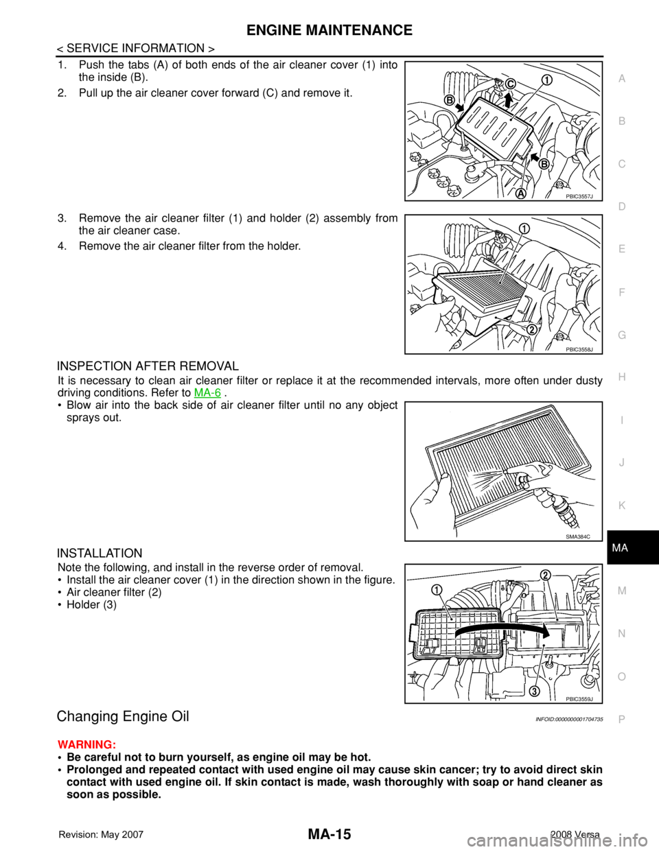
1. Push the tabs (A) of both ends of the air cleaner cover (1) into
the inside (B).
2. Pull up the air cleaner cover forward (C) and remove it.
3. Remove the air cleaner filter (1) and holder (2) assembly from
the air cleaner case.
4. Remove the air cleaner filter from the holder.
INSPECTION AFTER REMOVAL
It is necessary to clean air cleaner filter or replace it at the recommended intervals, more often under dusty
driving conditions. Refer to MA-6
.
• Blow air into the back side of air cleaner filter until no any object
sprays out.
INSTALLATION
Note the following, and install in the reverse order of removal.
• Install the air cleaner cover (1) in the direction shown in the figure.
• Air cleaner filter (2)
• Holder (3)
Changing Engine OilINFOID:0000000001704735
WARNING:
• Be careful not to burn yourself, as engine oil may be hot.
• Prolonged and repeated contact with used engine oil may cause skin cancer; try to avoid direct skin
contact with used engine oil. If skin contact is made, wash thoroughly with soap or hand cleaner as
soon as possible.
PBIC3557J
PBIC3558J
SMA384C
PBIC3559J
Page 2277 of 2771
ENGINE MAINTENANCE
MA-17
< SERVICE INFORMATION >
C
D
E
F
G
H
I
J
K
MA
B
MA
N
O
P
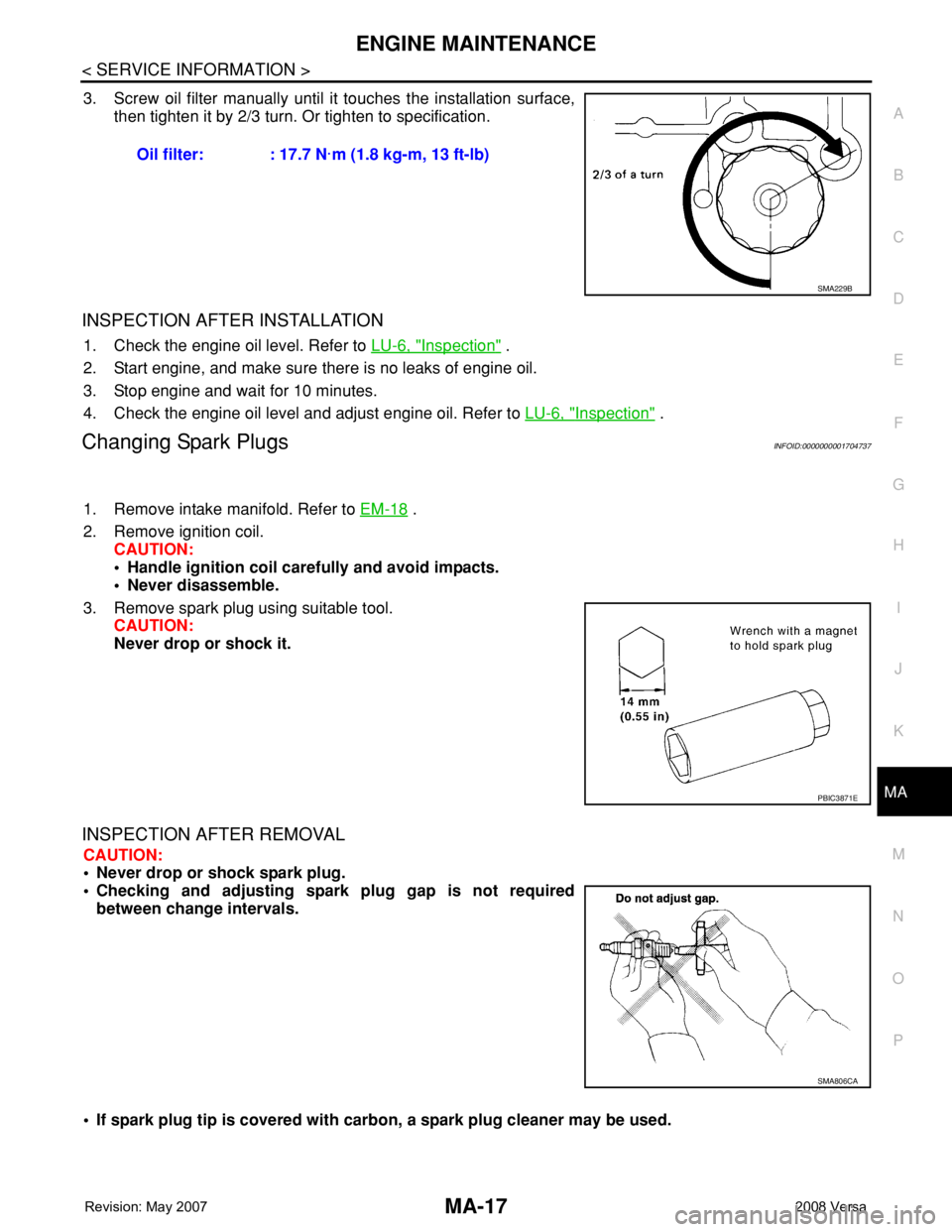
3. Screw oil filter manually until it touches the installation surface,
then tighten it by 2/3 turn. Or tighten to specification.
INSPECTION AFTER INSTALLATION
1. Check the engine oil level. Refer to LU-6, "Inspection" .
2. Start engine, and make sure there is no leaks of engine oil.
3. Stop engine and wait for 10 minutes.
4. Check the engine oil level and adjust engine oil. Refer to LU-6, "
Inspection" .
Changing Spark PlugsINFOID:0000000001704737
1. Remove intake manifold. Refer to EM-18 .
2. Remove ignition coil.
CAUTION:
• Handle ignition coil carefully and avoid impacts.
• Never disassemble.
3. Remove spark plug using suitable tool.
CAUTION:
Never drop or shock it.
INSPECTION AFTER REMOVAL
CAUTION:
• Never drop or shock spark plug.
• Checking and adjusting spark plug gap is not required
between change intervals.
• If spark plug tip is covered with carbon, a spark plug cleaner may be used. Oil filter: : 17.7 N·m (1.8 kg-m, 13 ft-lb)
SMA229B
PBIC3871E
SMA806CA
Page 2283 of 2771
CHASSIS AND BODY MAINTENANCE
MA-23
< SERVICE INFORMATION >
C
D
E
F
G
H
I
J
K
MA
B
MA
N
O
P
2. Stop engine.
3. Drain A/T fluid by removing the drain plug. Reinstall the drain plug to the specified torque.
CAUTION:
Do not reuse drain plug gasket.
4. Refill the transaxle with new specified A/T fluid through the A/T fluid charging pipe. Always refill the tran-
saxle with the same volume of A/T fluid that was drained out.
5. Run engine at idle speed for 5 minutes.
6. Check A/T fluid level and condition. Refer to MA-22, "
Checking A/T Fluid" .
Balancing WheelsINFOID:0000000001704749
Adjust wheel balance using road wheel center.
CAUTION:
• Be careful not to scratch the road wheel during removal.
• Use clip-on type wheel balance weights only.
Wheel balance (Maximum allowable unbalance):
RotationINFOID:0000000001704750
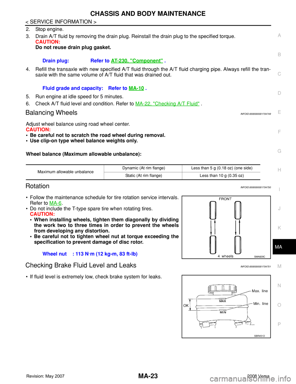
• Follow the maintenance schedule for tire rotation service intervals.
Refer to MA-6
.
• Do not include the T-type spare tire when rotating tires.
CAUTION:
• When installing wheels, tighten them diagonally by dividing
the work two to three times in order to prevent the wheels
from developing any distortion.
• Be careful not to tighten wheel nut at torque exceeding the
specification to prevent damage of disc rotor.
Checking Brake Fluid Level and LeaksINFOID:0000000001704751
• If fluid level is extremely low, check brake system for leaks.Drain plug: Refer to AT-230, "
Component" .
Fluid grade and capacity: Refer to MA-10
.
Maximum allowable unbalanceDynamic (At rim flange) Less than 5 g (0.18 oz) (one side)
Static (At rim flange) Less than 10 g (0.35 oz)
Wheel nut : 113 N·m (12 kg-m, 83 ft-lb)SMA829C
SBR451D
Page 2714 of 2771
WT-6
< SERVICE INFORMATION >
ROAD WHEEL TIRE ASSEMBLY
ROAD WHEEL TIRE ASSEMBLY
Balancing WheelsINFOID:0000000001703749
Adjust wheel balance using road wheel center.
CAUTION:
• Be careful not to scratch the road wheel during removal.
• Use clip-on type wheel balance weights only.
Wheel balance (Maximum allowable unbalance):
RotationINFOID:0000000001703750
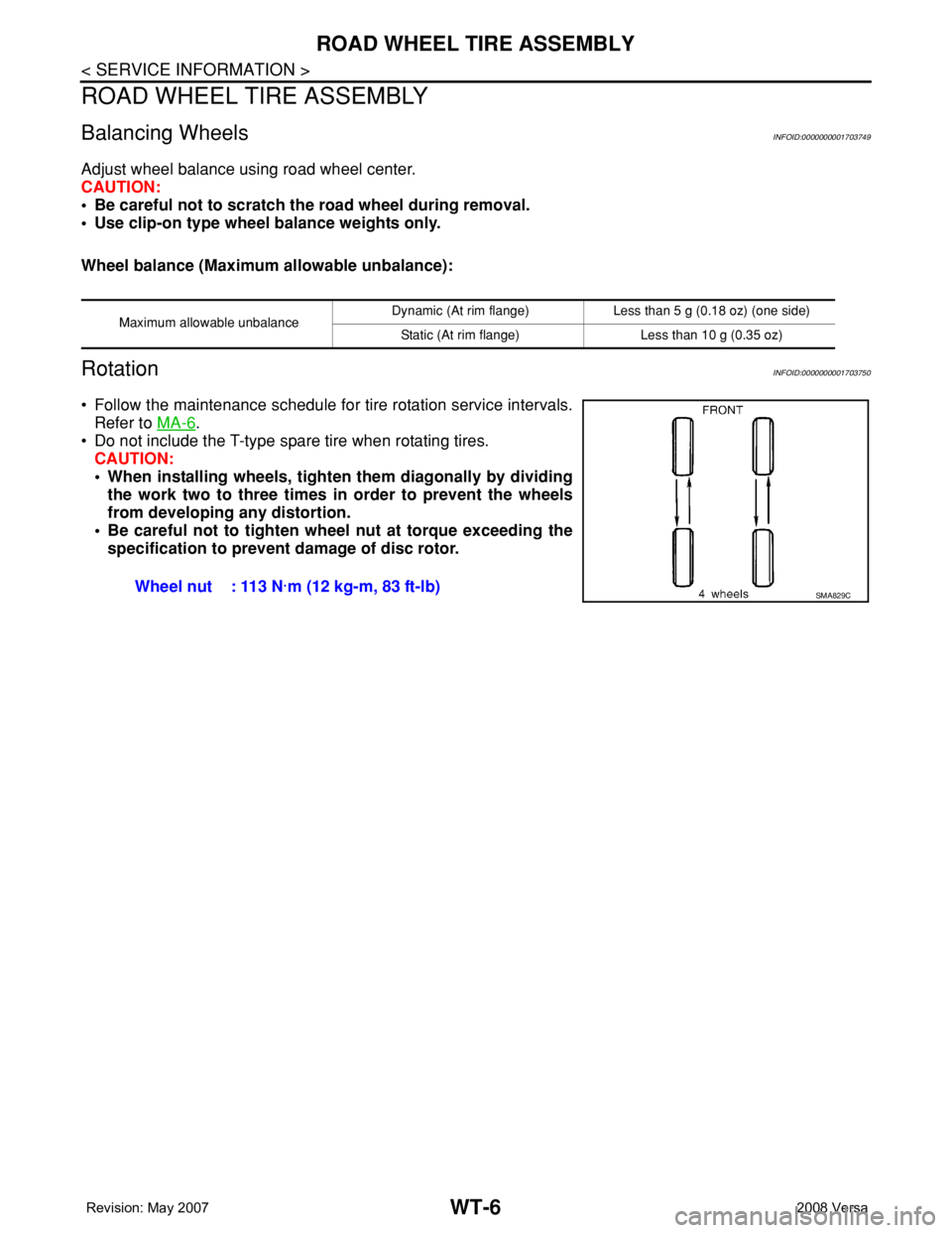
• Follow the maintenance schedule for tire rotation service intervals.
Refer to MA-6
.
• Do not include the T-type spare tire when rotating tires.
CAUTION:
• When installing wheels, tighten them diagonally by dividing
the work two to three times in order to prevent the wheels
from developing any distortion.
• Be careful not to tighten wheel nut at torque exceeding the
specification to prevent damage of disc rotor.
Maximum allowable unbalanceDynamic (At rim flange) Less than 5 g (0.18 oz) (one side)
Static (At rim flange) Less than 10 g (0.35 oz)
Wheel nut : 113 N·m (12 kg-m, 83 ft-lb)SMA829C
Page 2737 of 2771

WW-4
< SERVICE INFORMATION >
FRONT WIPER AND WASHER SYSTEM
• to front wiper high relay (located in IPDM E/R), and
• to CPU (located in IPDM E/R),
• through 10A fuse [No. 6, located in fuse block (J/B)]
• to BCM terminal 38,
• through 15A fuse [No. 4, located in fuse block (J/B)]
• to combination switch terminal 14.
Ground is supplied
• to IPDM E/R terminals 39 and 59, and
• to front wiper motor terminal 2
• through grounds E15 and E24
• to BCM terminal 67, and
• to combination switch terminal 12
• through grounds M57 and M61.
LOW SPEED WIPER OPERATION
When the front wiper switch is in LO position, the BCM detects the low speed wiper ON signal by means of the
BCM wiper switch reading function.
The BCM sends a front wiper request signal (LO) through the CAN communication line
• from BCM terminals 39 and 40
• to IPDM E/R terminals 40 and 41.
When the IPDM E/R receives front wiper request signal (LO), it turns ON front wiper relay, located in IPDM E/
R, power is supplied
• through IPDM E/R terminal 33 and front wiper high relay and front wiper relay
• to front wiper motor terminal 3.
Ground is supplied
• to front wiper motor terminal 2
• through grounds E15 and E24.
With power and ground is supplied, front wiper motor operates at low speed.
HIGH SPEED WIPER OPERATION
When the front wiper switch is in HI position, the BCM detects a high speed wiper ON signal by means of the
BCM wiper switch reading function.
The BCM sends a front wiper request signal (HI) through the CAN communication line
• from BCM terminals 39 and 40
• to IPDM E/R terminals 40 and 41.
When the IPDM E/R receives front wiper request signal (HI), it turns ON front wiper relay and front wiper high
relay, located in IPDM E/R, power is supplied
• through IPDM E/R terminal 32
• to front wiper motor terminal 5.
Ground is supplied
• to front wiper motor terminal 2
• through grounds E15 and E24.
With power and ground is supplied, front wiper motor operates at high speed.
INTERMITTENT OPERATION
Wiper intermittent operation delay interval is determined from the intermittent wiper dial position inputs. During
each intermittent operation delay interval, the BCM sends a front wiper request signal to the IPDM E/R to
operate the wipers.
When the ignition switch is in the ON or START position, and the front wiper switch is turned to the intermittent
position, the BCM detects a front wiper (intermittent) ON signal by means of the BCM wiper switch reading
function.
BCM then sends front wiper (intermittent) request signal through the CAN communication lines
• from BCM terminals 39 and 40
• to IPDM E/R terminals 40 and 41.
When BCM determines that combination switch status is front wiper intermittent ON, it performs the following
operations.
• BCM detects ON/OFF status of intermittent wiper dial position
• BCM calculates operation interval from wiper dial position.
• BCM sends a front wiper request signal (INT) to IPDM E/R at calculated operation interval.
When IPDM E/R receives the front wiper request signal (INT), it supplies ground to energize the front wiper
relay. It then sends auto-stop signal to the BCM and conducts intermittent front wiper motor operation.