2008 NISSAN LATIO air bleeding
[x] Cancel search: air bleedingPage 802 of 2771
CL-1
TRANSMISSION/TRANSAXLE
D
E
F
G
H
I
J
K
L
M
SECTION CL
A
B
CL
N
O
P
CONTENTS
CLUTCH
SERVICE INFORMATION ............................2
PRECAUTIONS ...................................................2
Precaution for Supplemental Restraint System
(SRS) "AIR BAG" and "SEAT BELT PRE-TEN-
SIONER" ...................................................................
2
Precaution for Procedure without Cowl Top Cover ......2
Service Notice or Precaution .....................................2
PREPARATION ...................................................3
Special Service Tool .................................................3
Commercial Service Tool ..........................................3
NOISE, VIBRATION AND HARSHNESS
(NVH) TROUBLESHOOTING .............................
4
NVH Troubleshooting Chart ......................................4
CLUTCH PEDAL .................................................5
On-vehicle Inspection and Adjustment ......................5
Removal and Installation ...........................................6
CLUTCH FLUID ...................................................8
Air Bleeding Procedure .............................................8
CLUTCH MASTER CYLINDER .........................9
Removal and Installation ..........................................9
CSC (CONCENTRIC SLAVE CYLINDER) .......11
Removal and Installation .........................................11
CLUTCH PIPING ...............................................12
Removal and Installation .........................................12
CLUTCH DISC, CLUTCH COVER AND FLY-
WHEEL ..............................................................
13
Removal and Installation .........................................13
SERVICE DATA AND SPECIFICATIONS
(SDS) .................................................................
16
Clutch Control System .............................................16
Clutch Pedal ............................................................16
Clutch Disc ..............................................................16
Clutch Cover ............................................................16
Page 807 of 2771
CL-6
< SERVICE INFORMATION >
CLUTCH PEDAL
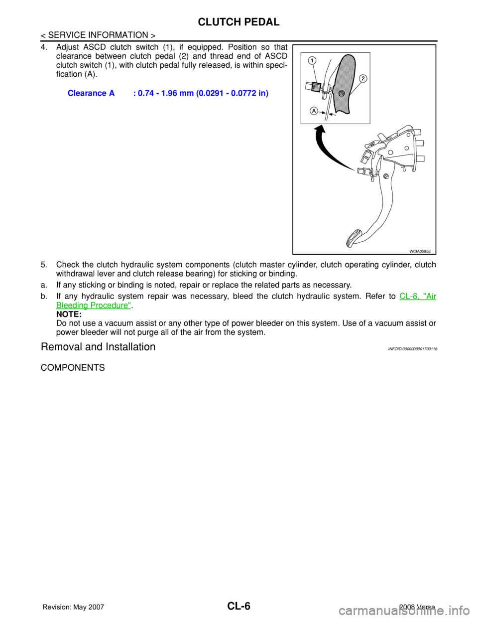
4. Adjust ASCD clutch switch (1), if equipped. Position so that
clearance between clutch pedal (2) and thread end of ASCD
clutch switch (1), with clutch pedal fully released, is within speci-
fication (A).
5. Check the clutch hydraulic system components (clutch master cylinder, clutch operating cylinder, clutch
withdrawal lever and clutch release bearing) for sticking or binding.
a. If any sticking or binding is noted, repair or replace the related parts as necessary.
b. If any hydraulic system repair was necessary, bleed the clutch hydraulic system. Refer to CL-8, "
Air
Bleeding Procedure".
NOTE:
Do not use a vacuum assist or any other type of power bleeder on this system. Use of a vacuum assist or
power bleeder will not purge all of the air from the system.
Removal and InstallationINFOID:0000000001703118
COMPONENTS
Clearance A : 0.74 - 1.96 mm (0.0291 - 0.0772 in)
WCIA0595E
Page 809 of 2771
CL-8
< SERVICE INFORMATION >
CLUTCH FLUID
CLUTCH FLUID
Air Bleeding ProcedureINFOID:0000000001703119
CAUTION:
Do not spill clutch fluid onto painted surfaces. If it spills, wipe up immediately and wash the affected
area with water.
NOTE:
• Do not use a vacuum assist or any other type of power bleeder on this system. Use of a vacuum assist or
power bleeder will not purge all the air from the system.
• Carefully monitor fluid level in reservoir tank during bleeding operation.
1. Fill master cylinder reservoir tank with new clutch fluid.
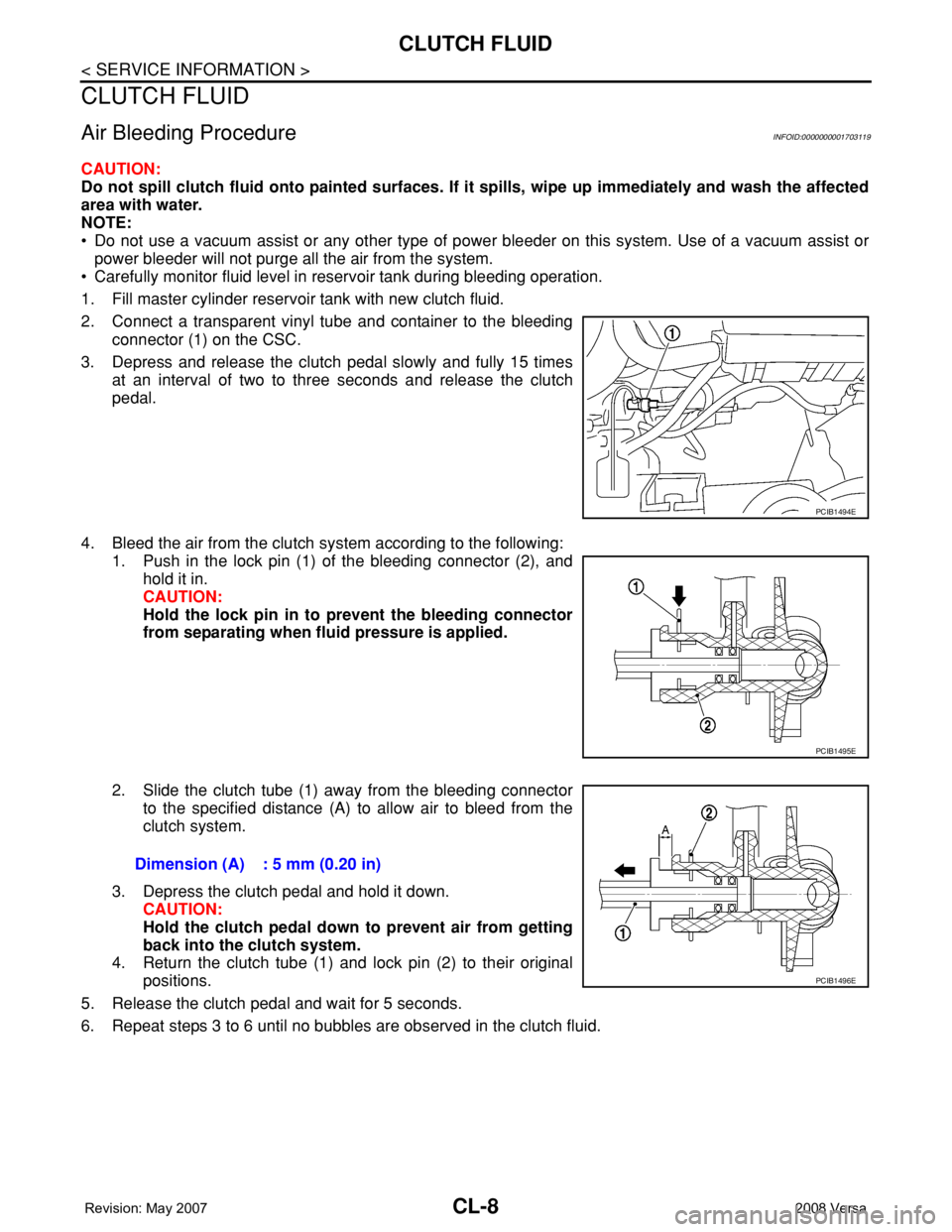
2. Connect a transparent vinyl tube and container to the bleeding
connector (1) on the CSC.
3. Depress and release the clutch pedal slowly and fully 15 times
at an interval of two to three seconds and release the clutch
pedal.
4. Bleed the air from the clutch system according to the following:
1. Push in the lock pin (1) of the bleeding connector (2), and
hold it in.
CAUTION:
Hold the lock pin in to prevent the bleeding connector
from separating when fluid pressure is applied.
2. Slide the clutch tube (1) away from the bleeding connector
to the specified distance (A) to allow air to bleed from the
clutch system.
3. Depress the clutch pedal and hold it down.
CAUTION:
Hold the clutch pedal down to prevent air from getting
back into the clutch system.
4. Return the clutch tube (1) and lock pin (2) to their original
positions.
5. Release the clutch pedal and wait for 5 seconds.
6. Repeat steps 3 to 6 until no bubbles are observed in the clutch fluid.
PCIB1494E
PCIB1495E
Dimension (A) : 5 mm (0.20 in)
PCIB1496E
Page 812 of 2771
CSC (CONCENTRIC SLAVE CYLINDER)
CL-11
< SERVICE INFORMATION >
D
E
F
G
H
I
J
K
L
MA
B
CL
N
O
P
CSC (CONCENTRIC SLAVE CYLINDER)
Removal and InstallationINFOID:0000000001703121
CAUTION:
• If transaxle assembly is removed from the vehicle, always replace CSC (Concentric slave cylinder).
Return CSC insert to original position to remove transaxle assembly. Dust on clutch disc sliding
parts may damage CSC seal and may cause clutch fluid leakage.
• Keep painted surface of the body and other parts free of clutch fluid. If it spills, wipe up immediately
and wash the affected area with water.
REMOVAL
1. Remove transaxle assembly. Refer to MT-16, "Removal and Installation".
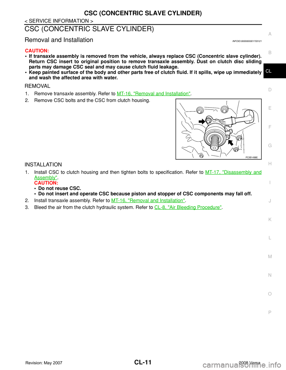
2. Remove CSC bolts and the CSC from clutch housing.
INSTALLATION
1. Install CSC to clutch housing and then tighten bolts to specification. Refer to MT-17, "Disassembly and
Assembly".
CAUTION:
• Do not reuse CSC.
• Do not insert and operate CSC because piston and stopper of CSC components may fall off.
2. Install transaxle assembly. Refer to MT-16, "
Removal and Installation".
3. Bleed the air from the clutch hydraulic system. Refer to CL-8, "
Air Bleeding Procedure".
PCIB1498E
Page 813 of 2771
CL-12
< SERVICE INFORMATION >
CLUTCH PIPING
CLUTCH PIPING
Removal and InstallationINFOID:0000000001703122
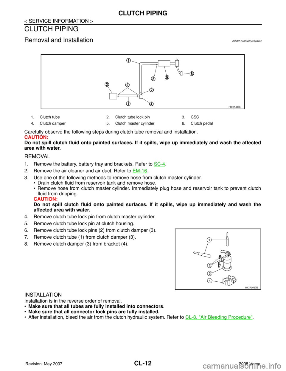
Carefully observe the following steps during clutch tube removal and installation.
CAUTION:
Do not spill clutch fluid onto painted surfaces. If it spills, wipe up immediately and wash the affected
area with water.
REMOVAL
1. Remove the battery, battery tray and brackets. Refer to SC-4.
2. Remove the air cleaner and air duct. Refer to EM-16
.
3. Use one of the following methods to remove hose from clutch master cylinder.
• Drain clutch fluid from reservoir tank and remove hose.
• Remove hose from clutch master cylinder. Immediately plug hose and reservoir tank to prevent clutch
fluid from dripping.
CAUTION:
Do not spill clutch fluid onto painted surfaces. If it spills, wipe up immediately and wash the
affected area with water.
4. Remove clutch tube lock pin from clutch master cylinder.
5. Remove clutch tube lock pin at clutch housing.
6. Remove clutch tube lock pins (2) from clutch damper (3).
7. Remove clutch tube (1) from clutch damper (3).
8. Remove clutch damper (3) from bracket (4).
INSTALLATION
Installation is in the reverse order of removal.
•Make sure that all tubes are fully installed into connectors.
•Make sure that all connector lock pins are fully installed.
• After installation, bleed the air from the clutch hydraulic system. Refer to CL-8, "
Air Bleeding Procedure".
1. Clutch tube 2. Clutch tube lock pin 3. CSC
4. Clutch damper 5. Clutch master cylinder 6. Clutch pedal
PCIB1499E
WCIA0597E
Page 2305 of 2771
TRANSAXLE ASSEMBLY
MT-17
< SERVICE INFORMATION >
D
E
F
G
H
I
J
K
L
MA
B
MT
N
O
P
When installing transaxle assembly, be careful not to bring transaxle input shaft into contact with
clutch cover.
• If transaxle is removed from the vehicle, always replace CSC. Refer to CL-11, "
Removal and Installation".
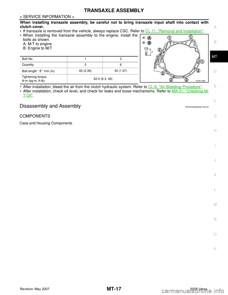
• When installing the transaxle assembly to the engine, install the
bolts as shown.
A: M/T to engine
B: Engine to M/T
• After installation, bleed the air from the clutch hydraulic system. Refer to CL-8, "
Air Bleeding Procedure".
• After installation, check oil level, and check for leaks and loose mechanisms. Refer to MA-21, "
Checking M/
T Oil".
Disassembly and AssemblyINFOID:0000000001703142
COMPONENTS
Case and Housing Components
Bolt No. 1 2
Quantity 3 6
Bolt length “ ” mm (in)60 (2.36) 50 (1.97)
Tightening torque
N·m (kg-m, ft-lb)62.0 (6.3, 46)
PCIB1786E
Page 2570 of 2771
REAR SUSPENSION BEAM
RSU-11
< SERVICE INFORMATION >
C
D
F
G
H
I
J
K
L
MA
B
RSU
N
O
P
REAR SUSPENSION BEAM
Removal and InstallationINFOID:0000000001703741
REMOVAL
1. Remove rear tires from vehicle using power tool.
2. Separate parking brake rear cable from rear drum brake and rear suspension beam. Refer to PB-4
.
3. Remove wheel sensor and wheel sensor harness from wheel hub and bearing assembly and rear suspen-
sion beam. Refer to BRC-32
.
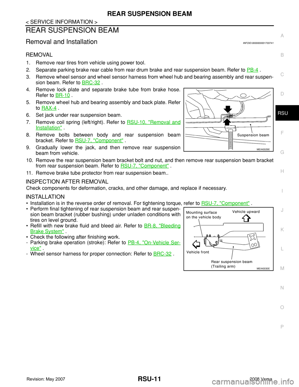
4. Remove lock plate and separate brake tube from brake hose.
Refer to BR-10
.
5. Remove wheel hub and bearing assembly and back plate. Refer
to RAX-4
.
6. Set jack under rear suspension beam.
7. Remove coil spring (left/right). Refer to RSU-10, "
Removal and
Installation" .
8. Remove bolts between body and rear suspension beam
bracket. Refer to RSU-7, "
Component" .
9. Gradually lower the jack, and then remove rear suspension
beam from vehicle.
10. Remove the rear suspension beam bracket bolt and nut, and then remove rear suspension beam bracket
from rear suspension beam. Refer to RSU-7, "
Component" .
11. Remove brake tube protector from rear suspension beam..
INSPECTION AFTER REMOVAL
Check components for deformation, cracks, and other damage, and replace if necessary.
INSTALLATION
• Installation is in the reverse order of removal. For tightening torque, refer to RSU-7, "Component" .
• Perform final tightening of rear suspension beam and rear suspen-
sion beam bracket (rubber bushing) under unladen conditions with
tires on level ground.
• Refill with new brake fluid and bleed air. Refer to BR-8, "
Bleeding
Brake System" .
• Check the following after finishing work.
- Parking brake operation (stroke): Refer to PB-4, "
On-Vehicle Ser-
vice" .
- Wheel sensor harness for proper connection: Refer to BRC-32
.
MEIA0029E
MEIA0030E