Page 116 of 241

ACTUATOR
MULTIPORT FUEL SYSTEM (MFI)13A-23
ACTUATORM2132002000353
INJECTOR
An injector is an injection nozzle with the electromagnetic valve
that injects fuel based on the injection signal sent by ECM. 1
injector is installed in the intake manifold of each cylinder and
fixed to the fuel rail. When electricity flows through the solenoid
coil, the plunger gets sucked in. The ball valve is integrated
with the plunger, and gets pulled together with the plunger till
the fully open position so that the injection hole is fully open
and the fuel gets injected.
Voltage from the battery gets applied from the injector relay to
the injector and up to the ECM. ECM turns ON its power tran
-
sistor and prepares the injector's ground circuit. Thus, current
flows through the injector while power transistor is ON and the
injector injects fuel.
AK602272AC
Fuel
Plate Ball valvePlunger Solenoid coilConnector
Filter
AK602578
From ETACS-ECUFrom MFI relay
Injector relay
Injectors
OFF ON
ECM
AC
No. 1 No. 2 No. 3 No. 4
Page 117 of 241

ACTUATOR
MULTIPORT FUEL SYSTEM (MFI)13A-24
THROTTLE ACTUATOR CONTROL MOTOR
A throttle actuator control motor is installed in throttle body. The
throttle actuator control motor performs the Open/Close of the
throttle valve through the reduction gear. ECM changes current
direction according to the Open/Close direction and also
changes current to the motor coil to control the throttle actuator
control motor.
Throttle actuator control motor is composed of a good
response, low energy, and small DC motor with brush and can
generate rotation force corresponding to the current applied on
the coil. When there is no current passing through the throttle
actuator control motor, the throttle valve remains at a pre
-
scribed opening angle. So, even if current stops because of a
fault in the system, a minimum level of running remains possi
-
ble.
AK604125AB
Throttle body
Throttle actuator
control motor
AK602231
Throttle actuator
control motor
Throttle actuator
control motor relayMFI relay
To ECM
Power supplyOFFON
OFF
ON
AE
From battery
ECM
Page 118 of 241

ACTUATOR
MULTIPORT FUEL SYSTEM (MFI)13A-25
IGNITION COIL
Refer to GROUP 16 − Ignition Coil P.16-2.
EXHAUST GAS RECIRCULATION (EGR) VALVE
Refer to GROUP 17 − Emission Control − Exhaust Gas Recircu-
lation (EGR) System P.17-12.
EVAPORATIVE EMISSION PURGE SOLENOID
Refer to GROUP 17 − Emission Control − Evaporative Emission
Control System
P.17-11.
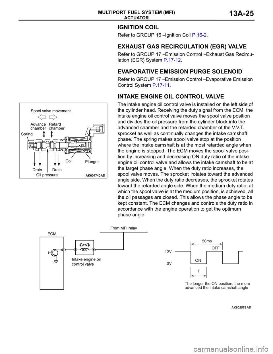
INTAKE ENGINE OIL CONTROL VALVE
The intake engine oil control valve is installed on the left side of
the cylinder head. Receiving the duty signal from the ECM, the
intake engine oil control valve moves the spool valve position
and divides the oil pressure from the cylinder block into the
advanced chamber and the retarded chamber of the V.V.T.
sprocket as well as continually changes the intake camshaft
phase. The spring makes spool valve stop at the position
where the intake camshaft is at the most retarded angle when
the engine is stopped. The ECM moves the spool valve posi
-
tion by increasing and decreasing ON duty ratio of the intake
engine oil control valve and allows the intake camshaft to be at
the target phase angle. When the duty ratio increases, the
spool valve moves. The sprocket rotates toward the advanced
angle side. When the duty ratio decreases, the sprocket rotates
toward the retarded angle side. When the medium duty ratio, at
which the spool valve is at the medium position, is achieved, all
the oil passages are closed. This allows the phase angle to be
kept constant. The ECM changes and controls the duty ratio in
accordance with the engine operation to get the optimum
phase angle.
AK604740AD
Spool valve movement
Retard
chamber
Spring
Drain
Oil pressureCoil
Plunger
Drain Advance
chamber
AK602579
ECM
Intake engine oil
control valve12VOFF
ON
T50ms
0V
AD
From MFI relay
The longer the ON position, the more
advanced the intake camshaft angle
Page 119 of 241

ACTUATOR
MULTIPORT FUEL SYSTEM (MFI)13A-26
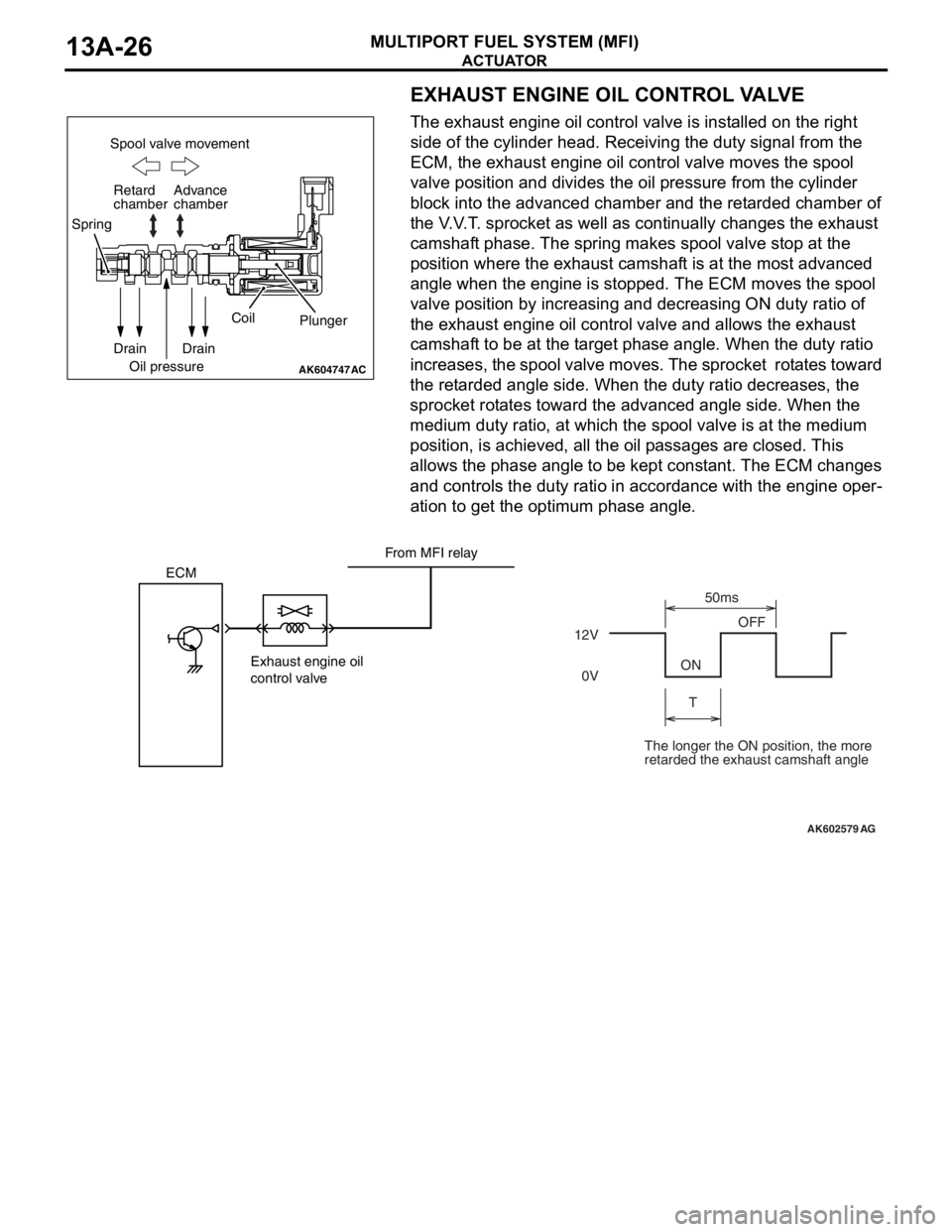
EXHAUST ENGINE OIL CONTROL VALVE
The exhaust engine oil control valve is installed on the right
side of the cylinder head. Receiving the duty signal from the
ECM, the exhaust engine oil control valve moves the spool
valve position and divides the oil pressure from the cylinder
block into the advanced chamber and the retarded chamber of
the V.V.T. sprocket as well as continually changes the exhaust
camshaft phase. The spring makes spool valve stop at the
position where the exhaust camshaft is at the most advanced
angle when the engine is stopped. The ECM moves the spool
valve position by increasing and decreasing ON duty ratio of
the exhaust engine oil control valve and allows the exhaust
camshaft to be at the target phase angle. When the duty ratio
increases, the spool valve moves. The sprocket rotates toward
the retarded angle side. When the duty ratio decreases, the
sprocket rotates toward the advanced angle side. When the
medium duty ratio, at which the spool valve is at the medium
position, is achieved, all the oil passages are closed. This
allows the phase angle to be kept constant. The ECM changes
and controls the duty ratio in accordance with the engine oper
-
ation to get the optimum phase angle.
AK604747
Spool valve movement
Retard
chamber
Spring
Drain
Oil pressureCoil
Plunger
Drain Advance
chamber
AC
AK602579
ECM
Exhaust engine oil
control valve12VOFF
ON
T50ms
0V
AG
From MFI relay
The longer the ON position, the more
retarded the exhaust camshaft angle
Page 120 of 241

ACTUATOR
MULTIPORT FUEL SYSTEM (MFI)13A-27
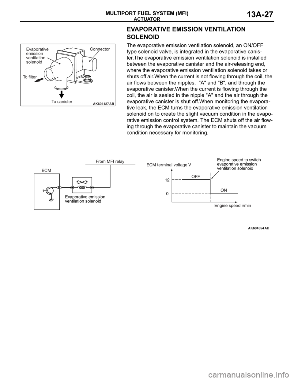
EVAPORATIVE EMISSION VENTILATION
SOLENOID
The evaporative emission ventilation solenoid, an ON/OFF
type solenoid valve, is integrated in the evaporative canis
-
ter.The evaporative emission ventilation solenoid is installed
between the evaporative canister and the air-releasing end,
where the evaporative emission ventilation solenoid takes or
shuts off air.When the current is not flowing through the coil, the
air flows between the nipples, "A" and "B", and through the
evaporative canister.When the current is flowing through the
coil, the air is sealed in the nipple "A" and the air through the
evaporative canister is shut off.When monitoring the evapora
-
tive leak, the ECM turns the evaporative emission ventilation
solenoid on to create the slight vacuum condition in the evapo
-
rative emission control system. The ECM shuts off the air flow-
ing through the evaporative canister to maintain the vacuum
condition necessary for monitoring.
AK604127ABTo canisterConnector
Evaporative
emission
ventilation
solenoid
To filter
AK604554
12
0
AB
OFF
ON ECMECM terminal voltage V
Engine speed r/min From MFI relay
Evaporative emission
ventilation solenoidEngine speed to switch
evaporative emission
ventilation solenoid
Page 128 of 241
IGNITION TIMING AND CONTROL FOR CURRENT CARRYING TIME
MULTIPORT FUEL SYSTEM (MFI)13A-35
IGNITION TIMING AND CONTROL FOR CURRENT
CARRYING TIME
M2132027100089
Ignition timing is pre-set according to engine driving
conditions. Compensations are made according to
pre-set values depending on conditions such as
engine coolant temperature, battery voltage etc. to
decide optimum ignition timing. Primary current con
-
nect/disconnect signal is sent to the power transistor
to control ignition timing. Ignition is done in sequence
of cylinders 1, 3, 4, 2.
System Configuration Diagram
AK502722AD
ECM MFI relay
Spark plugs Ignition
coils
Cylinder No. 1 2 3 4Battery
Mass airflow sensor
Intake air temperature sensor
Manifold absolute
pressure sensor
Engine coolant
temperature sensor
Intake camshaft position sensor
Exhaust camshaft position sensor
Crankshaft position sensor
Knock sensor
Ignition switch-ST Throttle position sensor
Page 131 of 241

THROTTLE VALVE OPENING ANGLE CONTROL AND IDLE SPEED CONTROL
MULTIPORT FUEL SYSTEM (MFI)13A-38
THROTTLE VALVE OPENING ANGLE CONTROL AND IDLE
SPEED CONTROL
M2132003500328
ECM detects the amount of accelerator pedal
depression (as per operator's intention) through the
accelerator pedal position sensor. Based on pre-set
basic target opening angles it adds various compen
-
sations and controls the throttle valve opening angle
according to the target opening angle.
While starting
ECM adds various compensations to the target
opening angle that are set based on the engine cool
-
ant temperature, so that the air volume is optimum
for starting.
While idling
ECM controls the throttle valve to achieve the target
opening angle that are set based on the engine cool
-
ant temperature. In this way best idle operation is
achieved when engine is cold and when it is hot.
Also, the following compensations ensure optimum
control.
While driving
Compensations are made to the target opening
angle set according to the accelerator pedal opening
angle and engine speed to control the throttle valve
opening angle.
AK602236AE
Throttle
position
sensorMain
Main Sub
SubMotor drive circuit
A/C switch (CAN) Engine coolant
temperature sensor
Intake air temperature
sensor
Crankshaft position sensor
Power steering pressure
switch
Generator FR terminal
Transmission range
switch (CAN) Motor drive power supply
(From throttle actuator
control motor relay)
Throttle actuator
control motor
Control unit
Barometric pressure
sensor Accelerator
pedal position
sensor
ECM
Page 138 of 241
MULTIPORT FUEL INJECTION (MFI) RELAY CONTROL
MULTIPORT FUEL SYSTEM (MFI)13A-45
MULTIPORT FUEL INJECTION (MFI) RELAY CONTROLM2132006000173
When the ignition switch-IG "ON" signal is input,
ECM turns ON the power transistor for control of the
MFI relay. As a result, current flows through the MFI
relay's coil, the relay switch turns ON and power is
supplied to each sensor and actuator. Also, when
ignition switch-IG "OFF" signal is input, ECM per
-
forms the following controls and then turns OFF the
power transistor for control of MFI relay.
•Throttle valve initializing control
AK604134AB OFF
ON
IG2 STLOCK
ACC
IG1
MFI relay
Power
supply
MFI relay control Ignition switch-IGBattery
back up To each sensor and
actuatorIgnition switch
ETACS-ECU Battery
ECM