Page 40 of 241
A/C-ECU
HEATER, AIR CONDITIONING AND VENTILATION55-8
COMMUNICATION
A/C-ECU performs the signal transmission and
reception with each ECU via CAN (Controller Area
Network)*
1. Also, with the heater control panel, it
transmits and receives signals via serial communica
-
tion.
NOTE: : For details of CAN communication, refer to
GROUP 54C
− Controller Area Network P.54C-2.
CAN COMMUNICATION INPUT SIGNALS TABLE
DIAGNOSTIC FUNCTION
A/C-ECU has the following functions for easier sys-
tem checks.
•DIAGNOSTIC FUNCTION
•Service data output
•Actuator test
NOTE: For each item, refer to the Workshop Manual.
AC506202
ETACS-ECU Heater control panelSRS-ECU
Engine-ECU
Combination meter A/C-ECU
: Interactive communicationCAN communication
SERIAL communication
AC
SignalTransmitter ECU
Engine coolant temperature signalENGINE-ECU
Vehicle speed signal
Engine speed signal
Ambient temperature signalETACS-ECU
Wiper signal
Ignition key signal
Average ambient temperature signalCOMBINATION METER
Page 41 of 241

A/C COMPRESSOR
HEATER, AIR CONDITIONING AND VENTILATION55-9
A/C COMPRESSORM2551001100268
HIGH EFFICIENCY COMPRESSOR WITH
INTEGRATED OIL SEPARATOR
High efficiency compressor with integrated oil sepa-
rator has been adopted to enhance fuel economy by
reducing the A/C operating rate.
MAGNETIC CLUTCH WITH THERMAL
FUSE
At the compressor lock, the thermal fuse integrated
in the magnet clutch is blown due to the frictional
heat against the compressor in order to reduce risk
of the drive belt breakage. The thermal fuse, together
with the coil, is coated with resin to enhance resis
-
tance to corrosion.
2-STEP PROFILE COMPRESSOR
The centre area of the scroll in the compressor pro-
vides 2-step profile, and thickness of area "B" shown
in the figure has been increased to enhance
strength. With this feature, thickness of area "A"
shown where lesser load is applied is reduced, thus
compressor performance is enhanced by compress
-
ing refrigerant even in central area, comparing to the
previous model.
CONDENSERM2551001400140
The condenser has been integrated with the radiator (cooling
module) to optimise ventilation and reduce weight.
AC507301
aa bbAA
BB
AC
Section a - aSection b - b Front viewFront view <2-step profile
compressor>
AC608768
Condenser
AB
Radiator
Page 42 of 241
DUCT
HEATER, AIR CONDITIONING AND VENTILATION55-10
DUCTM2551001300358
The rear heater duct has been introduced, and the
air distribution ratio to front and rear seats has been
optimised in order to enhance the air heating perfor
-
mance for the rear seats, and to prevent the circula-
tion of cooled air back to the front seats.
with rear duct>
AC608058
To front door window
(Side defroster)
Side ventilator
Center ventilatorTo windshield (Defroster)
To front door window
(Side defroster)
To passenger seat footwell
To driver seat footwell
To rear seat footwell
(Vehicle with rear duct)
To rear seat footwell
(Vehicle with rear duct)
Side ventilator
AB
Page 43 of 241
VENTILATION SYSTEM
HEATER, AIR CONDITIONING AND VENTILATION55-11
VENTILATION SYSTEMM2551002000554
Fresh air is sucked from the front deck and
exhausted through the air outlet behind the rear
bumper. Optimizing areas of the outside air induction
hole and the air outlet enhances ventilated air
amount, reducing noise.
AC608060Rear ventilator ductAB
Page 72 of 241

EMISSION CONTROL
ENGINE AND EMISSION CONTROL17-10
CRANKCASE VENTILATION SYSTEMM2171000400129
A blow-by gas reduction device prevents blow-by
gas from being expelled into the atmosphere and is
of closed type. A positive crankcase ventilation
(PCV) valve is provided in the ventilation hose from
the rocker cover to the intake manifold. During low
load driving, clean air is supplied to the crankcase by
the air intake hose via the breather hose and rocker
cover, and it mixes with the blow-by gas in the crank
-
case. The blow-by gas in the crankcase is induced to
the intake manifold through the rocker cover and
PCV valve. During high load driving, blow-by gas in
the crankcase is induced to the intake manifold
through the rocker cover and PCV valve and at the
same time also via the air intake hose and throttle
body due to negative pressure in the air cleaner.
Emission
reduction
systemsAir-fuel ratio
feedback
controlDecrease of CO, HC and NOx
Controls air-fuel ratio of air-fuel mixture to
become theoretical air-fuel ratio (about 14.7),
which is when the 3-way catalytic converter's
cleaning performance is best. It also controls
optimum fuel supply based on coolant
temperature, driving conditions etc.
•ECM
•Mass airflow sensor
•Injectors
•Heated oxygen sensor
•Crankshaft position sensor
etc.
Catalytic
converterDecrease of CO, HC and NOx
It facilitates oxidation of CO and HC and
reduction of NOx so that all 3 component gases
are cleaned simultaneously.
Monolith catalyst
HC trap
catalytic
converter
HC decrease
During cold operation of engine, exhaust HC is
temporarily absorbed. And then Exhaust HC is
released when temperature reaches to level at
which catalyst is activated. This allows HC to be
reduced.
Monolith catalyst
System Objective / Function Composition parts
AK604142
Air cleaner
PCV valve
AB
Ventilation hose
Breather hose
Flow of blow-by gas and clean air (low load area)
Flow of blow-by gas (high load area)
Page 74 of 241

EMISSION CONTROL
ENGINE AND EMISSION CONTROL17-12
EVAPORATIVE EMISSION PURGE SOLENOID
An evaporative emission purge solenoid is installed in the
intake manifold.The evaporative emission purge solenoid con
-
trols the intake volume of fuel vapor gas from the canister. The
evaporative emission purge solenoid is a duty control type
solenoid valve. When current is not passing through the coil,
nipple A is kept airtight and fuel vapor gas cannot be sucked in.
When current passes through the coil, air can pass between
nipple A and B and fuel vapor gas is sucked in. ECM changes
the ON duty ratio according to engine's operating condition to
control the intake volume of fuel vapor gas.
EXHAUST GAS RECIRCULATION (EGR) SYSTEM M2171000300122
When the combustion gas temperature becomes
high, generation of the environment polluting NOx
(nitrogen oxides) increases rapidly. EGR system is
used to decrease the volume of NOx generated.
EGR system re-circulates exhaust gas inside the
intake manifold. It increases specific heat of the com
-
bustion gases and reduces combustion speed to lower the combustion temperature and reduce the
volume of NOx generated. ECM calculates the EGR
introduction volume according to engine operating
conditions and controls the EGR valve opening angle
at optimum. Also, immediately after the ignition
switch ON signal is input, it drives fully closed step
-
per motor and performs initialization.
AK604745AC
B To canister
To intake manifoldA
AK602245AD
12V
ONOFF
0V100 ms
Evaporative
emission
purge solenoidFrom MFI relay
ECM
AK502987AE
ECMMass airflow sensor
Intake air temperature sensor
Manifold absolute
pressure sensor
Engine coolant
temperature sensor
Throttle position sensor
Crankshaft position sensor BatteryEGR valve
(stepper motor)
Page 120 of 241

ACTUATOR
MULTIPORT FUEL SYSTEM (MFI)13A-27
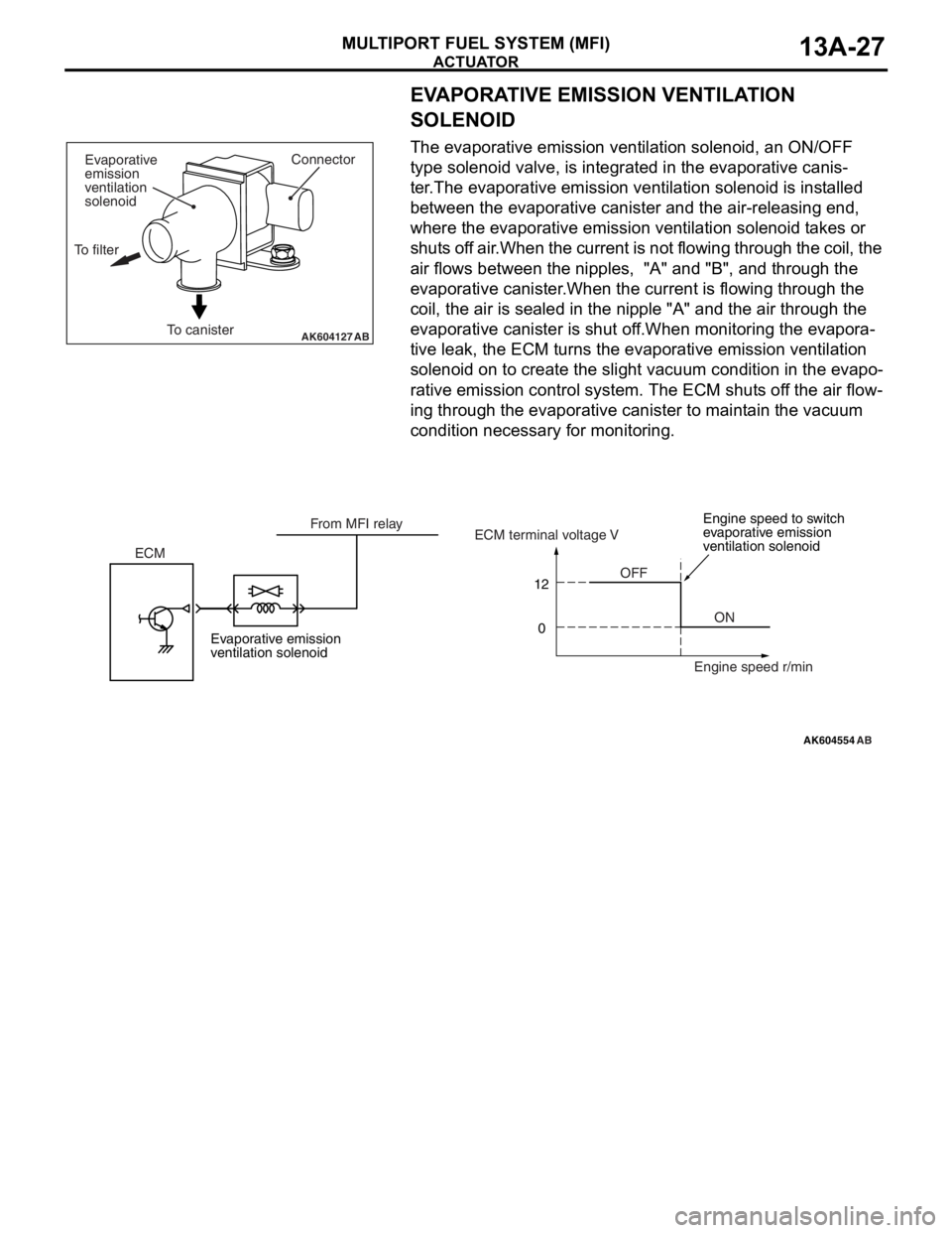
EVAPORATIVE EMISSION VENTILATION
SOLENOID
The evaporative emission ventilation solenoid, an ON/OFF
type solenoid valve, is integrated in the evaporative canis
-
ter.The evaporative emission ventilation solenoid is installed
between the evaporative canister and the air-releasing end,
where the evaporative emission ventilation solenoid takes or
shuts off air.When the current is not flowing through the coil, the
air flows between the nipples, "A" and "B", and through the
evaporative canister.When the current is flowing through the
coil, the air is sealed in the nipple "A" and the air through the
evaporative canister is shut off.When monitoring the evapora
-
tive leak, the ECM turns the evaporative emission ventilation
solenoid on to create the slight vacuum condition in the evapo
-
rative emission control system. The ECM shuts off the air flow-
ing through the evaporative canister to maintain the vacuum
condition necessary for monitoring.
AK604127ABTo canisterConnector
Evaporative
emission
ventilation
solenoid
To filter
AK604554
12
0
AB
OFF
ON ECMECM terminal voltage V
Engine speed r/min From MFI relay
Evaporative emission
ventilation solenoidEngine speed to switch
evaporative emission
ventilation solenoid
Page 122 of 241

FUEL INJECTION CONTROL
MULTIPORT FUEL SYSTEM (MFI)13A-29
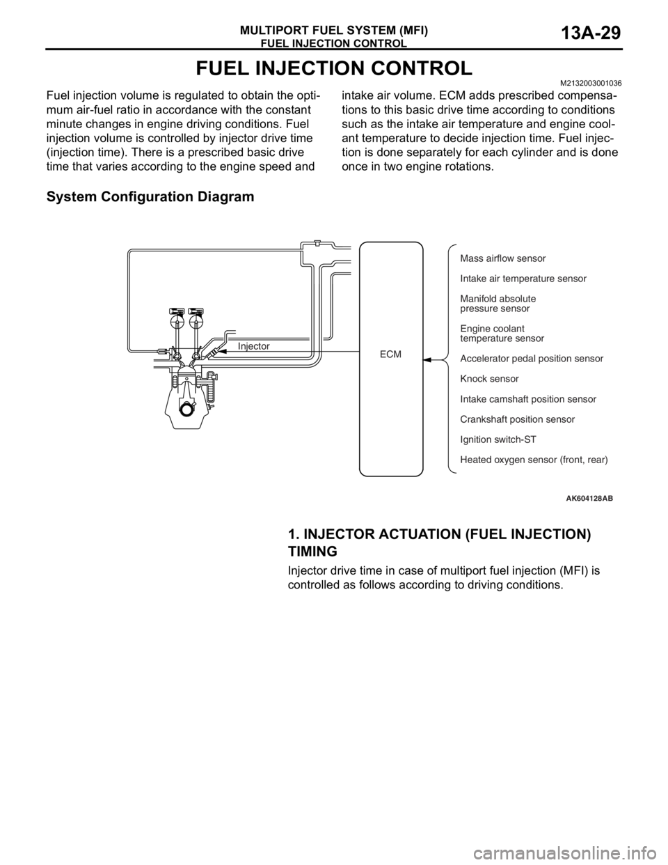
FUEL INJECTION CONTROLM2132003001036
Fuel injection volume is regulated to obtain the opti-
mum air-fuel ratio in accordance with the constant
minute changes in engine driving conditions. Fuel
injection volume is controlled by injector drive time
(injection time). There is a prescribed basic drive
time that varies according to the engine speed and intake air volume. ECM adds prescribed compensa
-
tions to this basic drive time according to conditions
such as the intake air temperature and engine cool
-
ant temperature to decide injection time. Fuel injec-
tion is done separately for each cylinder and is done
once in two engine rotations.
System Configuration Diagram
1. INJECTOR ACTUATION (FUEL INJECTION)
TIMING
Injector drive time in case of multiport fuel injection (MFI) is
controlled as follows according to driving conditions.
AK604128AB
ECM InjectorMass airflow sensor
Intake air temperature sensor
Manifold absolute
pressure sensor
Engine coolant
temperature sensor
Accelerator pedal position sensor
Knock sensor
Intake camshaft position sensor
Ignition switch-ST
Heated oxygen sensor (front, rear) Crankshaft position sensor