Page 310 of 474

309 Operation
Tires and wheels
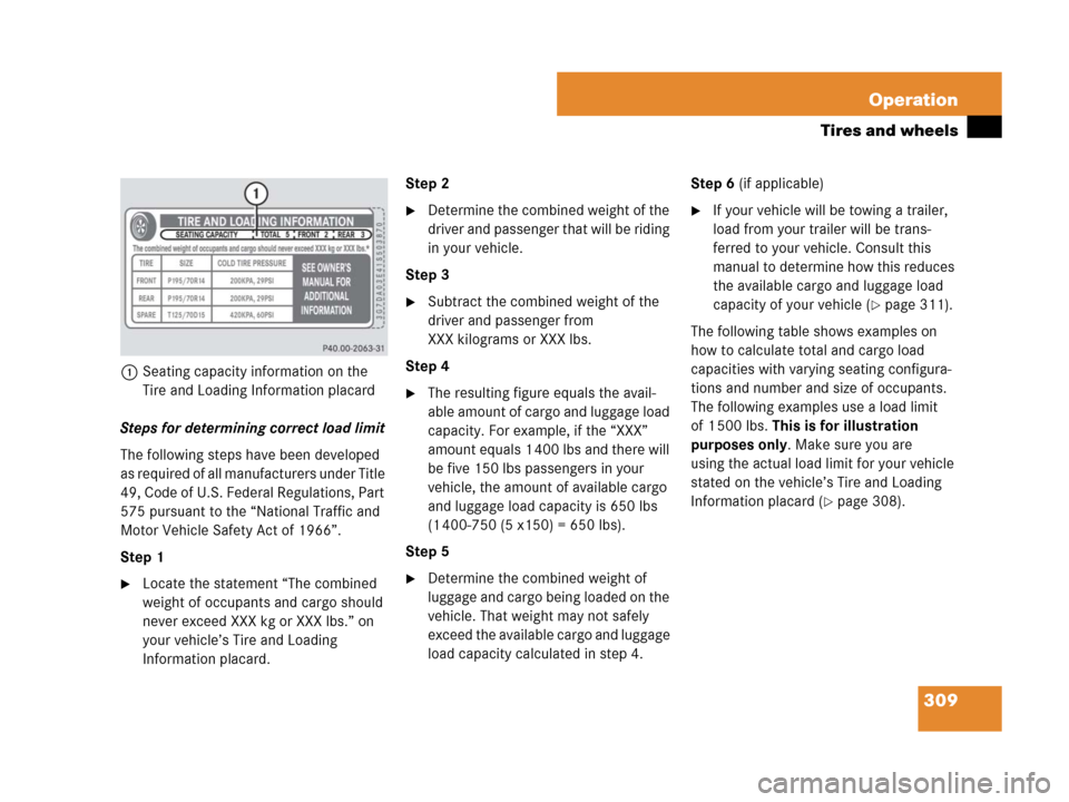
1Seating capacity information on the
Tire and Loading Information placard
Steps for determining correct load limit
The following steps have been developed
as required of all manufacturers under Title
49, Code of U.S. Federal Regulations, Part
575 pursuant to the “National Traffic and
Motor Vehicle Safety Act of 1966”.
Step 1
�Locate the statement “The combined
weight of occupants and cargo should
never exceed XXX kg or XXX lbs.” on
your vehicle’s Tire and Loading
Information placard.Step 2
�Determine the combined weight of the
driver and passenger that will be riding
in your vehicle.
Step 3
�Subtract the combined weight of the
driver and passenger from
XXX kilograms or XXX lbs.
Step 4
�The resulting figure equals the avail-
able amount of cargo and luggage load
capacity. For example, if the “XXX”
amount equals 1 400 lbs and there will
be five 150 lbs passengers in your
vehicle, the amount of available cargo
and luggage load capacity is 650 lbs
(1 400-750 (5 x150) = 650 lbs).
Step 5
�Determine the combined weight of
luggage and cargo being loaded on the
vehicle. That weight may not safely
exceed the available cargo and luggage
load capacity calculated in step 4.Step 6 (if applicable)
�If your vehicle will be towing a trailer,
load from your trailer will be trans-
ferred to your vehicle. Consult this
manual to determine how this reduces
the available cargo and luggage load
capacity of your vehicle (
�page 311).
The following table shows examples on
how to calculate total and cargo load
capacities with varying seating configura-
tions and number and size of occupants.
The following examples use a load limit
of 1 500 lbs. This is for illustration
purposes only. Make sure you are
using the actual load limit for your vehicle
stated on the vehicle’s Tire and Loading
Information placard (
�page 308).
Page 312 of 474

311 Operation
Tires and wheels
Certification label
Even after careful determination of the
combined weight of all occupants, cargo
and the trailer tongue load (if applicable)
(
�page 311) as to not exceed the permis-
sible load limit, you must make sure that
your vehicle never exceeds the Gross Vehi-
cle Weight Rating (GVWR) and the Gross
Axle Weight Rating (GAWR) for either the
front or rear axle. You can obtain the
GVWR and GAWR from the certification
label. The certification label can be found
on the driver’s door B-pillar, see “Technical
data” (
�page 438).
Gross Vehicle Weight Rating (GVWR):
The total weight of the vehicle, all
occupants, all cargo, and the trailer tongue
load (
�page 311) must never exceed
the GVWR.
Gross Axle Weight Rating (GAWR): The to-
tal allowable weight that can be carried by
a single axle (front or rear). To assure that your vehicle does not ex-
ceed the maximum permissible weight
limits (GVWR and GAWR for front and rear
axle), have the loaded vehicle (including
driver, passengers and all cargo and, if
applicable, trailer fully loaded) weighed on
a suitable commercial scale.
Trailer tongue load
The tongue load of any trailer is an impor-
tant weight to measure because it affects
the load you can carry in your vehicle. If a
trailer is towed, the tongue load must be
added to the weight of all occupants riding
and any cargo you are carrying in the
vehicle. The tongue load typically is
10 percent of the trailer weight and every-
thing loaded in it.
Your Mercedes-Benz has been designed
primarily to carry passengers and their
cargo. Mercedes-Benz does not recom-
mend trailer towing with your vehicle.
Recommended tire inflation pressure
Warning!G
Follow recommend tire inflation pressures.
Do not underinflate tires. Underinflated tires
wear excessively and/or unevenly,
adversely affect handling and fuel economy,
and are more likely to fail from being over-
heated.
Do not overinflate tires. Overinflated tires
can adversely affect handling and ride
comfort, wear unevenly, increase stopping
distance, and result in sudden deflation
(blowout) because they are more likely to
become punctured or damaged by road
debris, potholes etc.
��
Page 343 of 474

342 Operation
Vehicle care
Engine cleaning
Prior to cleaning the engine compartment,
make sure to protect electrical compo-
nents and connectors from the intrusion of
water and cleaning agents.
Corrosion protection, such as
MB Anticorrosion Wax should be applied to
the engine compartment after every en-
gine cleaning. Before applying, all control
linkage bushings and joints should be
lubricated. The poly-V-belt and all pulleys
should be protected from any wax.
Vehicle washing
In the winter, thoroughly remove all traces
of road salt as soon as possible.
When washing the vehicle underbody, do
not forget to clean the inner sides of the
wheels.Hand-wash
Do not use hot water or wash your vehicle
in direct sunlight.
�Use only a mild car wash detergent,
such as Mercedes-Benz approved Car
Shampoo.
�Thoroughly spray the vehicle with a
diffused jet of water.
Direct only a very weak spray towards
the ventilation intake.
�Use plenty of water and rinse the
sponge and chamois frequently.
�Rinse with clean water and thoroughly
dry with a chamois.
Do not allow cleaning agents to dry on
the finish.Automatic car wash
You can have your car washed in an auto-
matic car wash from the start. Automatic
car washes without brushes are prefera-
ble.
�To protect the filter system, switch the
climate control (
�page 178) or auto-
matic climate control (
�page 190) to
air recirculation mode.
If the vehicle is very dirty, prewash it be-
fore running it through the automatic car
wash.
!Do not use scouring agents on these parts.
Never apply strong force and only use a soft,
non-scratching cloth when cleaning the vehicle.
Do not attempt to wipe the surface with a dry
cloth or sponge.
Otherwise you may scratch or damage the paint.
!Do not clean your vehicle in an automatic
touchless car wash which uses caustic spray.
Otherwise the caustic spray will damage the
paint or ornamental moldings.
!Make sure that the windshield wiper switch
is set to0 (
�page 56). Otherwise, the rain
sensor* could activate and cause the wipers to
move unintentionally. This may lead to vehicle
damage.
Due to the width of the vehicle, fold in exterior
rear view mirrors prior to running the vehicle
through an automatic car wash to prevent
damage to the mirrors.
Page 348 of 474
347 Practical hints
What to do if …
Where will I find...?
Unlocking/locking in an emergency
Opening/closing in an emergency
Replacing SmartKey batteries
Replacing bulbs
Replacing wiper blades
Flat tire
Battery
Jump starting
Towing the vehicle
Fuses
Page 390 of 474
389 Practical hints
Where will I find...?
�Where will I find...?
First aid kit
The first aid kit is stored in a parcel net
behind the driver’s seat.Vehicle tool kit, vehicle jack
The vehicle tool kit is stored in a storage
compartment under the trunk floor.
The following is included:
�Collapsible wheel chock
�Vehicle jack
�Protective wrap (except SLK 55 AMG
with Performance Package)
�Alignment bolt
�Towing eye bolt
�Wheel wrench
�Valve extractor
�Electric air pump
�TIREFIT kit (SLK 55 AMG with
Performance Package only)Removing the vehicle tool kit
Vehicles with spare wheel
�Open the trunk (�page 99).
�Lift up trunk floor.
�Remove the spare wheel (�page 392).
You can now access the vehicle tool
kit.
iCheck expiration dates and contents for
completeness at least once a year and replace
missing/expired items.
��
Page 391 of 474

390 Practical hints
Where will I find...?
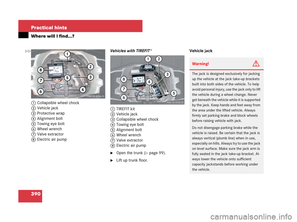
1Collapsible wheel chock
2Vehicle jack
3Protective wrap
4Alignment bolt
5Towing eye bolt
6Wheel wrench
7Valve extractor
8Electric air pumpVehicles with TIREFIT*
1TIREFIT kit
2Vehicle jack
3Collapsible wheel chock
4Towing eye bolt
5Alignment bolt
6Wheel wrench
7Valve extractor
8Electric air pump
�Open the trunk (�page 99).
�Lift up trunk floor.Vehicle jack
Warning!G
The jack is designed exclusively for jacking
up the vehicle at the jack take-up brackets
built into both sides of the vehicle. To help
avoid personal injury, use the jack only to lift
the vehicle during a wheel change. Never
get beneath the vehicle while it is supported
by the jack. Keep hands and feet away from
the area under the lifted vehicle. Always
firmly set parking brake and block wheels
before raising vehicle with jack.
Do not disengage parking brake while the
vehicle is raised. Be certain that the jack is
always vertical (plumb line) when in use,
especially on hills. Always try to use the jack
on level surface. Make sure the jack arm is
fully seated in the jack take-up bracket. Al-
ways lower the vehicle onto sufficient
capacity jackstands before working under
the vehicle.
��
Page 397 of 474

396 Practical hints
Unlocking/locking in an emergency
�Insert mechanical key 2 into the
driver’s door lock until it stops.
�Turn mechanical key 2 clockwise to
position1.
The driver’s door is locked.
�Turn back mechanical key 2 and
remove it from driver’s door lock.Manually unlocking the gear selector
lever (automatic transmission*)
In case of power failure, the gear selector
lever can be manually unlocked, e.g. to tow
the vehicle.
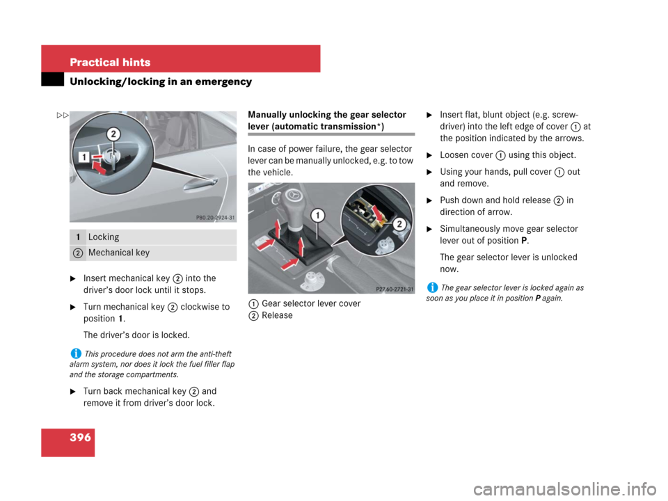
1Gear selector lever cover
2Release
�Insert flat, blunt object (e.g. screw-
driver) into the left edge of cover1 at
the position indicated by the arrows.
�Loosen cover1 using this object.
�Using your hands, pull cover1 out
and remove.
�Push down and hold release2 in
direction of arrow.
�Simultaneously move gear selector
lever out of positionP.
The gear selector lever is unlocked
now.1Locking
2Mechanical key
iThis procedure does not arm the anti-theft
alarm system, nor does it lock the fuel filler flap
and the storage compartments.
iThe gear selector lever is locked again as
soon as you place it in positionP again.
��
Page 408 of 474

407 Practical hints
Replacing wiper blades
Removing wiper blades
�Fold the wiper arms forward until they
engage.
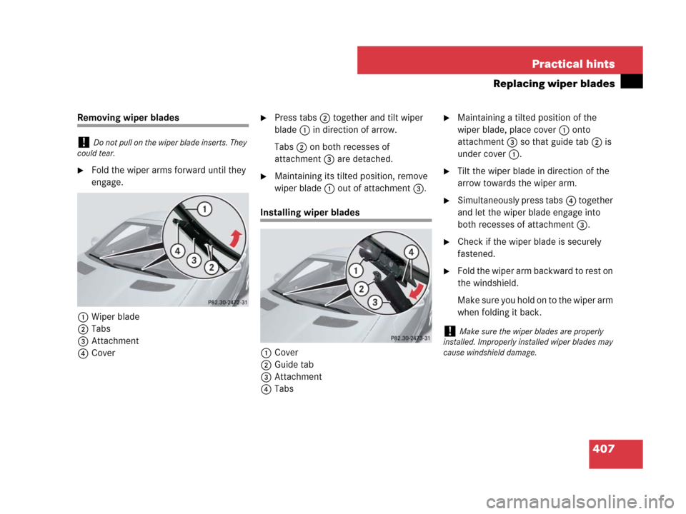
1Wiper blade
2Tabs
3Attachment
4Cover
�Press tabs2 together and tilt wiper
blade1 in direction of arrow.
Tabs2 on both recesses of
attachment3 are detached.
�Maintaining its tilted position, remove
wiper blade1 out of attachment3.
Installing wiper blades
1Cover
2Guide tab
3Attachment
4Tabs
�Maintaining a tilted position of the
wiper blade, place cover1 onto
attachment3 so that guide tab2 is
under cover1.
�Tilt the wiper blade in direction of the
arrow towards the wiper arm.
�Simultaneously press tabs4 together
and let the wiper blade engage into
both recesses of attachment3.
�Check if the wiper blade is securely
fastened.
�Fold the wiper arm backward to rest on
the windshield.
Make sure you hold on to the wiper arm
when folding it back.
!Do not pull on the wiper blade inserts. They
could tear.
!Make sure the wiper blades are properly
installed. Improperly installed wiper blades may
cause windshield damage.