Page 347 of 561

346 Operation
Engine compartment
The coolant expansion tank is located on
the driver’s side of the engine compart-
ment.
1Cap
2Coolant expansion tank
3Indicator wall
4Coolant level
�Using a rag, turn cap1 slowly approx-
imately one half turn counterclockwise
to release any excess pressure.
�Continue turning cap1 counterclock-
wise and remove it.
Coolant level4 is correct if the level:
�for cold coolant: reaches the top of
indicator wall3 visible through the
filling opening
�for warm coolant: is approximately
0.6 in (1.5 cm) higher
�Add coolant as required.
�Replace and tighten cap1.
For more information on coolant, see
“Coolants” (
�page 528).Windshield/rear window washer
system and headlamp cleaning
system*
The windshield washer reservoir is located
in the engine compartment.
1Cap for windshield washer reservoir
Fluid for the windshield/rear window
washer system and the headlamp cleaning
system* is supplied from the windshield
washer reservoir. It has a capacity of 8.1
US qt (7.7 l).
Page 348 of 561
347 Operation
Engine compartment
During all seasons, add MB Windshield
Washer Concentrate “MB SummerFit” to
water. Premix the windshield washer fluid
in a suitable container.
�Use the tab to pull cap1 upwards.
�Refill the reservoir with MB Windshield
Washer Concentrate “MB SummerFit”
and water (or commercially available
premixed windshield washer sol-
vent/antifreeze, depending on ambient
temperatures).
For more information, see “Windshield
washer system and headlamp cleaning
system*” (
�page 530).
Warning!G
Washer solvent/antifreeze is highly flamma-
ble. Do not spill washer solvent/antifreeze
on hot engine parts, because it may ignite
and burn. You could be seriously burned.!Always use washer solvent/antifreeze
where temperatures may fall below freezing
point. Failure to do so could result in damage to
the washer system/reservoir.
!Only use washer fluid which is suitable for
plastic lenses. Improper washer fluid can
damage the plastic lenses of the headlamps.
Page 350 of 561

349 Operation
Tires and wheels
Tire care and maintenance
Regularly check your tire inflation pressure
at least once a month. For more informa-
tion on checking tire inflation pressure,
see “Recommended tire inflation pres-
sure” (
�page 357).Tire inspection
Every time you check your tire inflation
pressure, you should also inspect your
tires for the following:
�excessive treadwear (�page 350)
�cord or fabric showing through the
tire’s rubber
�bumps, bulges, cuts, cracks or splits in
the tread or side of the tire
Replace the tire if you find any of the above
conditions.
Make sure you also inspect the spare tire
periodically for condition and inflation.
Spare tires will age and become worn over
time even if never used, and thus should be
inspected and replaced when necessary.Life of tire
The service life of a tire is dependent upon
varying factors including but not limited to:
�Driving style
�Tire inflation pressure
�Distance driven
Warning!G
Regularly check the tires for damage. Dam-
aged tires can cause tire inflation pressure
loss. As a result, you could lose control of
your vehicle.
Worn, old tires can cause accidents. If the
tire tread is badly worn, or if the tires have
sustained damage, replace them.
Warning!G
Tires and spare tire should be replaced after
6 years, regardless of the remaining tread.
Page 353 of 561

352 Operation
Tires and wheels
1Driver’s door B-pillar
Following is a discussion on how to work
with the information contained on the Tire
and Loading Information placard with
regards to loading your vehicle.Tire and Loading Information
Tire and Loading Information placard1Load limit information on the Tire and
Loading Information placard
The Tire and Loading Information placard
showing the load limit information is
located on the driver’s door B-pillar
(
�page 352).
�Locate the statement “The combined
weight of occupants and cargo should
never exceed XXX kilograms or
XXX lbs.” on the Tire and Loading Infor-
mation placard.
The combined weight of all occupants,
cargo/luggage and trailer tongue load
(if applicable) should never exceed the
weight referenced in that statement.
Warning!G
Do not overload the tires by exceeding the
specified load limit as indicated on the Tire
and Loading Information placard on the
driver’s door B-pillar. Overloading the tires
can overheat them, possibly causing a
blowout. Overloading the tires can also
result in handling or steering problems, or
brake failure.
iData shown on Tire and Loading Information
placard example are for illustration purposes
only. Load limit data are specific to each vehicle
and may vary from data shown in the illustration
below. Refer to Tire and Loading Information
placard on vehicle for actual data specific to your
vehicle.
Page 354 of 561

353 Operation
Tires and wheels
Seating capacity
The seating capacity gives you important
information on the number of occupants
that can be in the vehicle. Observe front
and rear seating capacity. The Tire and
Loading Information placard showing the
seating capacity is located on the driver’s
door B-pillar (
�page 352).
1Seating capacity information on the
Tire and Loading Information placard.
Steps for determining correct load limit
The following steps have been developed
as required of all manufacturers under
Title 49, Code of U.S. Federal Regulations,
Part 575 pursuant to the “National Traffic
and Motor Vehicle Safety Act of 1966”.Step 1
�Locate the statement “The combined
weight of occupants and cargo should
never exceed XXX kg or XXX lbs.” on
your vehicle’s Tire and Loading
Information placard.
Step 2
�Determine the combined weight of the
driver and passengers that will be
riding in your vehicle.
Step 3
�Subtract the combined weight of the
driver and passengers from
XXX kilograms or XXX lbs.
iData shown on Tire and Loading Information
placard example are for illustration purposes
only. Seating data are specific to each vehicle
and may vary from data shown in the illustration
below. Refer to Tire and Loading Information
placard on vehicle for actual data specific to your
vehicle.
��
Page 355 of 561

354 Operation
Tires and wheels
Step 4
�The resulting figure equals the avail-
able amount of cargo and luggage load
capacity. For example, if the “XXX”
amount equals 1400 lbs and there will
be five 150 lbs passengers in your
vehicle, the amount of available cargo
and luggage load capacity is 650 lbs
(1400-750 (5 x150) = 650 lbs).
Step 5
�Determine the combined weight of
luggage and cargo being loaded on the
vehicle. That weight may not safely
exceed the available cargo and luggage
load capacity calculated in step 4.Step 6 (if applicable)
�If your vehicle will be towing a trailer,
load from your trailer will be trans-
ferred to your vehicle. Consult this
manual to determine how this reduces
the available cargo and luggage load
capacity of your vehicle (
�page 356).
The following table shows examples on
how to calculate total and cargo load
capacities with varying seating configura-
tions and number and size of occupants.
The following examples use a load limit
of 1500 lbs. This is for illustration
purposes only. Make sure you are using
the actual load limit for your vehicle stated
on the vehicle’s Tire and Loading
Information placard (
�page 352).
��
Page 356 of 561
355 Operation
Tires and wheels
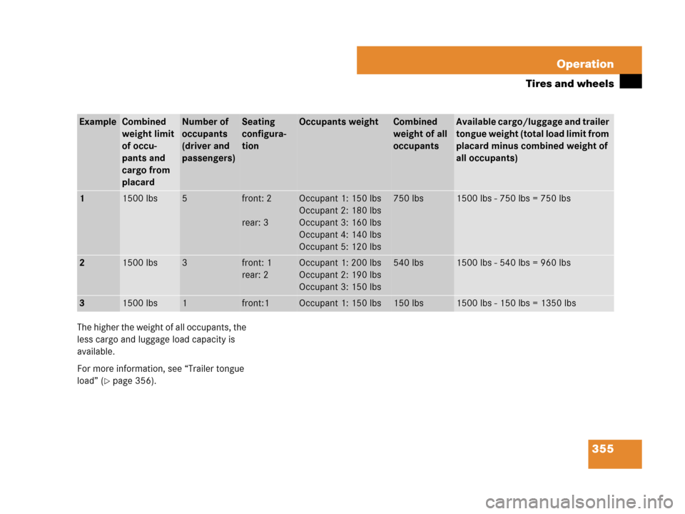
The higher the weight of all occupants, the
less cargo and luggage load capacity is
available.
For more information, see “Trailer tongue
load” (
�page 356).
ExampleCombined
weight limit
of occu-
pants and
cargo from
placardNumber of
occupants
(driver and
passengers)Seating
configura-
tionOccupants weight Combined
weight of all
occupantsAvailable cargo/luggage and trailer
tongue weight (total load limit from
placard minus combined weight of
all occupants)
11500 lbs5front: 2
rear: 3Occupant 1: 150 lbs
Occupant 2: 180 lbs
Occupant 3: 160 lbs
Occupant 4: 140 lbs
Occupant 5: 120 lbs750 lbs1500 lbs - 750 lbs = 750 lbs
21500 lbs3front: 1
rear: 2Occupant 1: 200 lbs
Occupant 2: 190 lbs
Occupant 3: 150 lbs540 lbs1500 lbs - 540 lbs = 960 lbs
31500 lbs1front:1Occupant 1: 150 lbs150 lbs1500 lbs - 150 lbs = 1350 lbs
Page 357 of 561

(
�page 356) as to not")
356 Operation
Tires and wheels
Certification label
Even after careful determination of the
combined weight of all occupants, cargo
and the trailer tongue load (if applicable)
(
�page 356) as to not exceed the permis-
sible load limit, you must make sure that
your vehicle never exceeds the Gross
Vehicle Weight Rating (GVWR) and the
Gross Axle Weight Rating (GAWR) for ei-
ther the front or rear axle. You can obtain
the GVWR and GAWR from the certification
label. The certification label can be found
on the driver’s door B-pillar, see “Technical
data” (
�page 507).Gross Vehicle Weight Rating (GVWR): The
total weight of the vehicle, all occupants,
all cargo, and the trailer tongue load
(
�page 356) must never exceed the
GVWR.
Gross Axle Weight Rating (GAWR): The to-
tal allowable weight that can be carried by
a single axle (front or rear).
To assure that your vehicle does not ex-
ceed the maximum permissible weight
limits (GVWR and GAWR for front and rear
axle), have the loaded vehicle (including
driver, passengers and all cargo and, if
applicable, trailer fully loaded) weighed on
a suitable commercial scale.Trailer tongue load
The tongue load of any trailer is an impor-
tant weight to measure because it affects
the load you can carry in your vehicle. If a
trailer is towed, the tongue load must be
added to the weight of all occupants riding
and any cargo you are carrying in the
vehicle. The tongue load typically is
between 8% and 15% of the trailer weight
and everything loaded in it.
For more information on trailer tongue
load, see “Loading a trailer” (
�page 329).