Page 471 of 561

470 Practical hints
Replacing bulbs
�Turn the hook or screwdriver 90°.
�Hold the cover1 and pull the hook or
screwdriver outwards.
You can now access the front fog lamp.
Example illustration ML350 (Sport Package
similar)
3Retaining screws
�Turn retaining screws3 counterclock-
wise.
�Remove front fog lamp2 out of the
bumper.
�Pull electrical connector off.4Bulb socket of front fog lamp bulb
�Turn bulb socket4 counterclockwise.
�Pull bulb socket4 out of the housing.
�Pull the front fog lamp bulb out of bulb
socket4.
�Insert the new front fog lamp bulb into
bulb socket4.
�Insert bulb socket4 into the housing.
�Turn bulb socket4 clockwise until it
engages.
�Plug in the electrical connector.
�Insert front fog lamp2 back into
bumper.
�Fasten retaining screws3.
�Reinsert cover1 and press it in until it
engages.
Additional turn signal lamps bulbs
The additional turn signal lamps in the
exterior rear view mirrors have LEDs.
If a malfunction occurs or LEDs fail to func-
tion, the entire turn signal unit must be re-
placed. Have the turn signal unit replaced
by an authorized Mercedes-Benz Light
Truck Center.
��
Page 472 of 561
471 Practical hints
Replacing bulbs
Replacing bulbs for rear lamps
Before you start to replace a bulb for a rear
lamp, do the following first:
�Turn the exterior lamp switch to
positionM (
�page 135).
Tail lamp unit
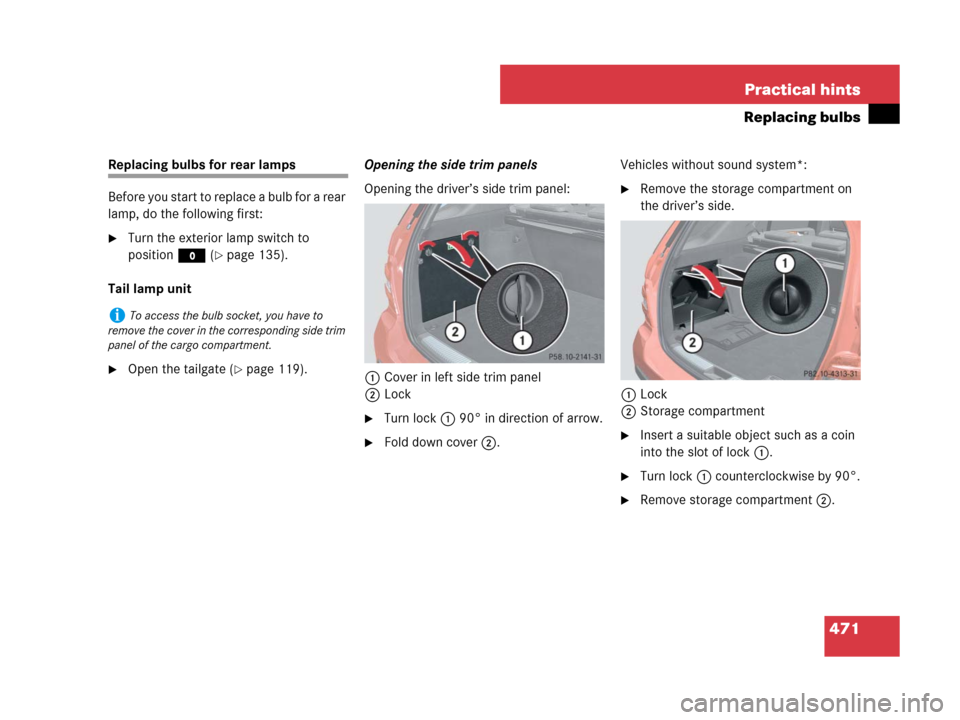
�Open the tailgate (�page 119).Opening the side trim panels
Opening the driver’s side trim panel:
1Cover in left side trim panel
2Lock
�Turn lock1 90° in direction of arrow.
�Fold down cover2.Vehicles without sound system*:
�Remove the storage compartment on
the driver’s side.
1Lock
2Storage compartment
�Insert a suitable object such as a coin
into the slot of lock1.
�Turn lock1 counterclockwise by 90°.
�Remove storage compartment2.
iTo access the bulb socket, you have to
remove the cover in the corresponding side trim
panel of the cargo compartment.
Page 473 of 561
472 Practical hints
Replacing bulbs
Opening the passenger side trim panel:
1Lock
2Cover in right side trim panel
�Insert a suitable object such as a coin
into the slot of lock1.
�Turn lock1 counterclockwise by 90°
in direction of arrow.
�Remove cover2.Replacing bulbs
Example illustration rear lamp passen-
ger-side
1Brake lamp
2Backup lamp
3Rear fog lamp (only driver’s side), tail
lamp, parking and standing lamp
4Side marker lamp
5Turn signal lamp
�Depending on which bulb needs to be
replaced, turn the respective bulb
socket1-5 counterclockwise.
�Press gently onto the respective bulb
and turn counterclockwise out of its
bulb socket.
�Press the new bulb gently into its bulb
socket and turn clockwise until it en-
gages.
�Align the respective bulb
socket1-5 and turn it clockwise.
�Make sure bulb socket is attached
properly.
�Close the respective cover in the cargo
compartment.
�Close the tailgate (�page 119).
Page 475 of 561
474 Practical hints
Replacing bulbs
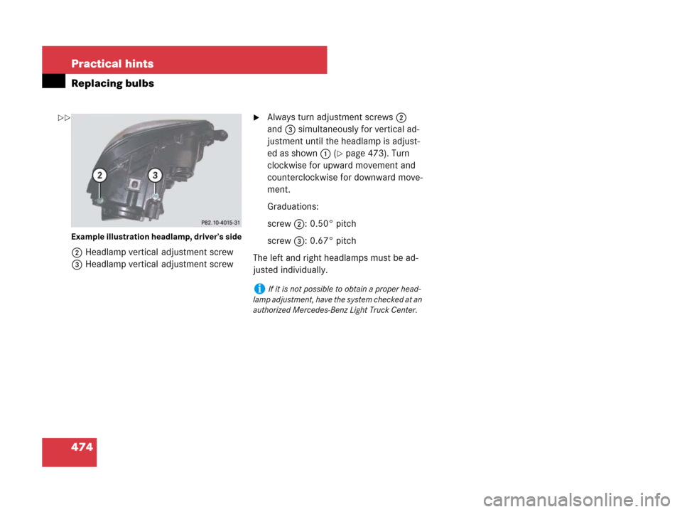
Example illustration headlamp, driver’s side
2Headlamp vertical adjustment screw
3Headlamp vertical adjustment screw
�Always turn adjustment screws2
and3 simultaneously for vertical ad-
justment until the headlamp is adjust-
ed as shown1 (
�page 473). Turn
clockwise for upward movement and
counterclockwise for downward move-
ment.
Graduations:
screw2: 0.50° pitch
screw3: 0.67° pitch
The left and right headlamps must be ad-
justed individually.
iIf it is not possible to obtain a proper head-
lamp adjustment, have the system checked at an
authorized Mercedes-Benz Light Truck Center.
��
Page 484 of 561
483 Practical hints
Flat tire
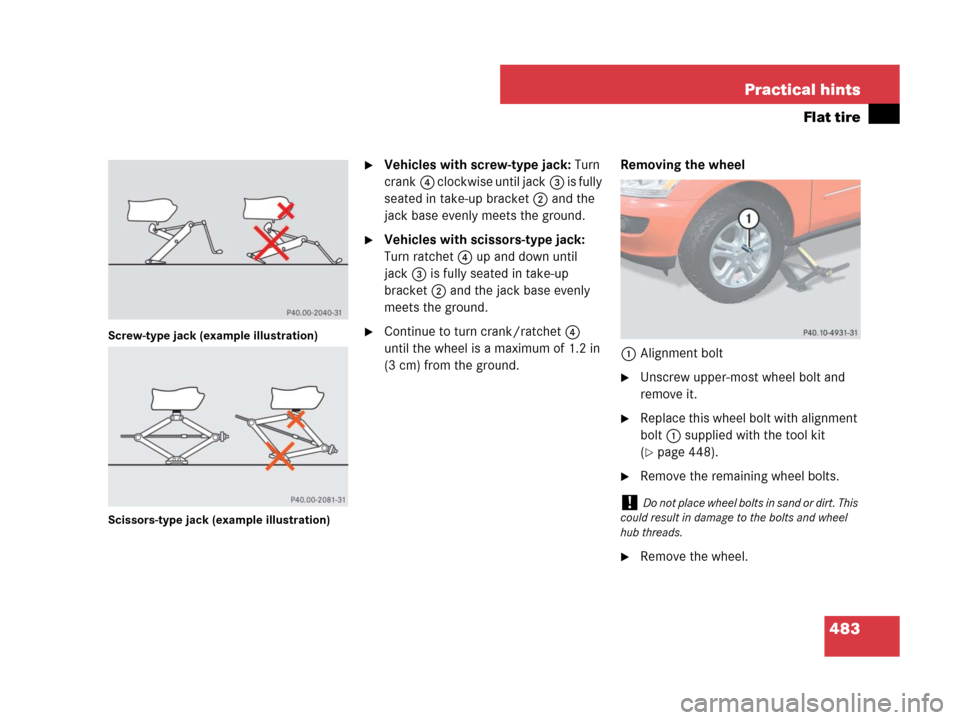
Screw-type jack (example illustration)
Scissors-type jack (example illustration)
�Vehicles with screw-type jack: Turn
crank4 clockwise until jack3 is fully
seated in take-up bracket2 and the
jack base evenly meets the ground.
�Vehicles with scissors-type jack:
Turn ratchet4 up and down until
jack3 is fully seated in take-up
bracket2 and the jack base evenly
meets the ground.
�Continue to turn crank/ratchet4
until the wheel is a maximum of 1.2 in
(3 cm) from the ground.Removing the wheel
1Alignment bolt
�Unscrew upper-most wheel bolt and
remove it.
�Replace this wheel bolt with alignment
bolt1 supplied with the tool kit
(
�page 448).
�Remove the remaining wheel bolts.
�Remove the wheel.
!Do not place wheel bolts in sand or dirt. This
could result in damage to the bolts and wheel
hub threads.
Page 488 of 561

487 Practical hints
Flat tire
Lowering the vehicle
�Vehicles with scissors-type jack:
Attach ratchet to vehicle jack in such a
way that the wordDOWN can be seen.
�Lower the vehicle until its resting fully
on its own weight.
�Vehicles with screw-type jack:
Turn crank counterclockwise.
�Vehicles with scissors-type jack:
Turn ratchet in Direction of DOWN.
�Remove the jack.1-5Wheel bolts
�Tighten the five wheel bolts evenly, fol-
lowing the diagonal sequence illustrat-
ed (1 to 5), until all bolts are tight.
Observe a tightening torque of
110 lb-ft (150 Nm).
�Store jack and all other vehicle tool kit
items back into the storage well.
Warning!G
Vehicles with collapsible tire
(ML 63 AMG only):
Inflate collapsible tire only after the wheel is
properly mounted.
Inflate the collapsible tire using the electric
pump (
�page 485) before lowering the
vehicle.
Warning!G
Have the tightening torque checked after
changing a wheel. The wheels could come
loose if they are not tightened to a torque of
110 lb-ft (150 Nm).
iThe removed road wheel cannot be stored in
the spare wheel well under the cargo compart-
ment floor, but should be transported in the car-
go compartment wrapped in a protective cover.
Vehicles with TPMS or Advanced TPMS*:
Do not activate the tire inflation pressure moni-
tor until a full size wheel/tire with functioning
sensor has been placed back into service on the
vehicle.
Page 497 of 561
.
�Connect the negative lead to the nega-
tive terminal (
�page 494).
Charging th")
496 Practical hints
Battery
�Connect the positive lead to the posi-
tive terminal and fasten it’s cover
(
�page 494).
�Connect the negative lead to the nega-
tive terminal (
�page 494).
Charging the battery
If the battery is discharged, the battery can
be charged using the jump-start contacts
located in the engine compartment
(
�page 498).
�Charge the battery in accordance with
the instructions of the battery charger
manufacturer.
Batteries contain materials that can harm
the environment if disposed of improperly.
Large 12-volt storage batteries contain
lead. Recycling of batteries is the preferred
method of disposal. Many states require
sellers of batteries to accept old batteries
for recycling.
!Never invert the terminal connections!
iThe following procedures must be carried
out following any interruption of battery power
(e.g. due to reconnection):
�Set the clock (�page 169).
Vehicles with COMAND system with naviga-
tion module*: Time and date are set auto-
matically.
�Synchronize the door windows
(
�page 237).
�Synchronize the power tilt/sliding sunroof
(
�page 242).
�Synchronize the power folding exterior rear
view mirrors* (
�page 200).
Warning!G
Never charge a battery while still installed in
the vehicle unless the accessory battery
charge unit approved by Mercedes-Benz is
being used. Gases may escape during charg-
ing and cause explosions that may result in
paint damage, corrosion or personal injury.
An accessory battery charge unit specially
adapted for Mercedes-Benz vehicles and
tested and approved by Mercedes-Benz is
available, permitting the charging of the
battery in its installed position. Contact an
authorized Mercedes-Benz Light Truck
Center for information and availability.
Charge battery in accordance with the
separate instructions for the accessory
battery charger.
��
Page 503 of 561
502 Practical hints
Towing the vehicle
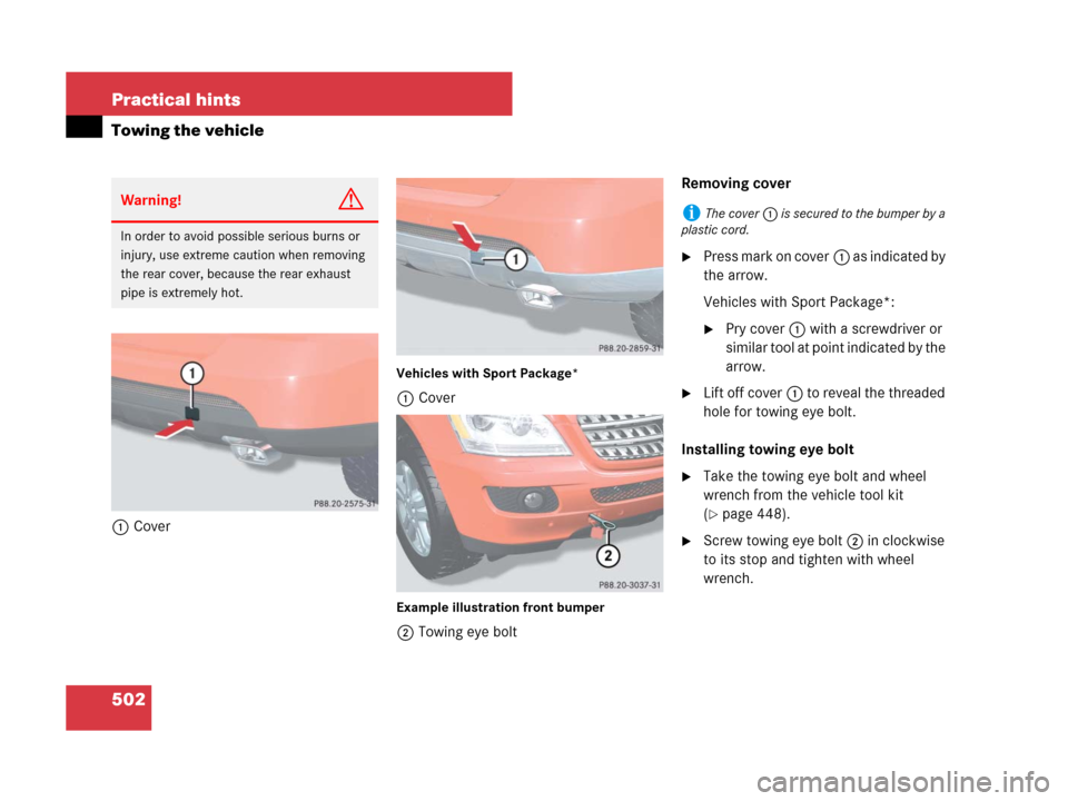
1Cover
Vehicles with Sport Package*
1Cover
Example illustration front bumper
2Towing eye boltRemoving cover
�Press mark on cover1 as indicated by
the arrow.
Vehicles with Sport Package*:
�Pry cover1 with a screwdriver or
similar tool at point indicated by the
arrow.
�Lift off cover1 to reveal the threaded
hole for towing eye bolt.
Installing towing eye bolt
�Take the towing eye bolt and wheel
wrench from the vehicle tool kit
(
�page 448).
�Screw towing eye bolt2 in clockwise
to its stop and tighten with wheel
wrench.
Warning!G
In order to avoid possible serious burns or
injury, use extreme caution when removing
the rear cover, because the rear exhaust
pipe is extremely hot.
iThe cover1 is secured to the bumper by a
plastic cord.