Page 347 of 561

346 Operation
Engine compartment
The coolant expansion tank is located on
the driver’s side of the engine compart-
ment.
1Cap
2Coolant expansion tank
3Indicator wall
4Coolant level
�Using a rag, turn cap1 slowly approx-
imately one half turn counterclockwise
to release any excess pressure.
�Continue turning cap1 counterclock-
wise and remove it.
Coolant level4 is correct if the level:
�for cold coolant: reaches the top of
indicator wall3 visible through the
filling opening
�for warm coolant: is approximately
0.6 in (1.5 cm) higher
�Add coolant as required.
�Replace and tighten cap1.
For more information on coolant, see
“Coolants” (
�page 528).Windshield/rear window washer
system and headlamp cleaning
system*
The windshield washer reservoir is located
in the engine compartment.
1Cap for windshield washer reservoir
Fluid for the windshield/rear window
washer system and the headlamp cleaning
system* is supplied from the windshield
washer reservoir. It has a capacity of 8.1
US qt (7.7 l).
Page 452 of 561
451 Practical hints
Where will I find ...?
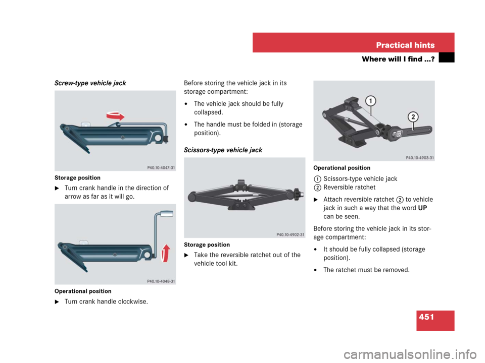
Screw-type vehicle jack
Storage position
�Turn crank handle in the direction of
arrow as far as it will go.
Operational position
�Turn crank handle clockwise.Before storing the vehicle jack in its
storage compartment:
�The vehicle jack should be fully
collapsed.
�The handle must be folded in (storage
position).
Scissors-type vehicle jack
Storage position
�Take the reversible ratchet out of the
vehicle tool kit.
Operational position
1Scissors-type vehicle jack
2Reversible ratchet
�Attach reversible ratchet2 to vehicle
jack in such a way that the wordUP
can be seen.
Before storing the vehicle jack in its stor-
age compartment:
�It should be fully collapsed (storage
position).
�The ratchet must be removed.
Page 454 of 561
.
Removing Minispare wheel
1Retaining screw
2Storage well casing
3Minispa")
453 Practical hints
Where will I find ...?
The Minispare wheel is located underneath
the cargo compartment floor
(
�page 448).
Removing Minispare wheel
1Retaining screw
2Storage well casing
3Minispare wheelFor access the Minispare wheel, see “Vehi-
cle tool kit” (
�page 448).
�Loosen retaining screw1 by turning it
counterclockwise.
�Remove storage well casing2.
�Remove Minispare wheel3.
Collapsible tire (ML 63 AMG only)
iFor information on how to mount the
Minispare wheel, see “Mounting the spare
wheel” (
�page 479).
iRemove Minispare wheel to gain access to
remaining tools in the vehicle tool kit
(
�page 448).
Warning!G
The dimensions of the collapsible tire are
different from those of the road wheels. As
a result, the vehicle handling characteristics
change when driving with a collapsible tire
mounted. Adapt your driving style accord-
ingly.
The collapsible tire is for temporary use
only. When driving with a collapsible tire
mounted, ensure proper tire inflation
pressure and do not exceed a vehicle speed
of 50 mph (80 km/h).
Drive to the nearest Mercedes-Benz Light
Truck Center as soon as possible to have the
collapsible tire replaced with a regular road
wheel.
Never operate the vehicle with more than
one collapsible tire mounted.
Do not switch off the ESP
® when a
collapsible tire is mounted.
Page 455 of 561
454 Practical hints
Where will I find ...?
The collapsible tire is located underneath
the cargo compartment floor
(
�page 448).
Removing the collapsible tire
1Electric air pump
2Collapsible tire
3Vehicle tool kit storage well casing
4Alignment bolt
5Towing eye bolt
6Wheel wrenchFor access the collapsible tire, see “Vehi-
cle tool kit” (
�page 448).
�Remove the vehicle tool kit storage
well casing3.
7Retaining screw
�Loosen retaining screw7 by turning it
counterclockwise.
�Remove collapsible tire2.
iFor information on how to mount the
collapsible tire, see “Mounting the spare wheel”
(
�page 479).
iRemove collapsible tire to gain access to
remaining tools in the vehicle tool kit
(
�page 448).
Page 456 of 561
455 Practical hints
Unlocking/locking in an emergency
�Unlocking/locking in an emergency
Unlocking the vehicle
If you cannot unlock the vehicle with the
SmartKey or KEYLESS-GO*, open the
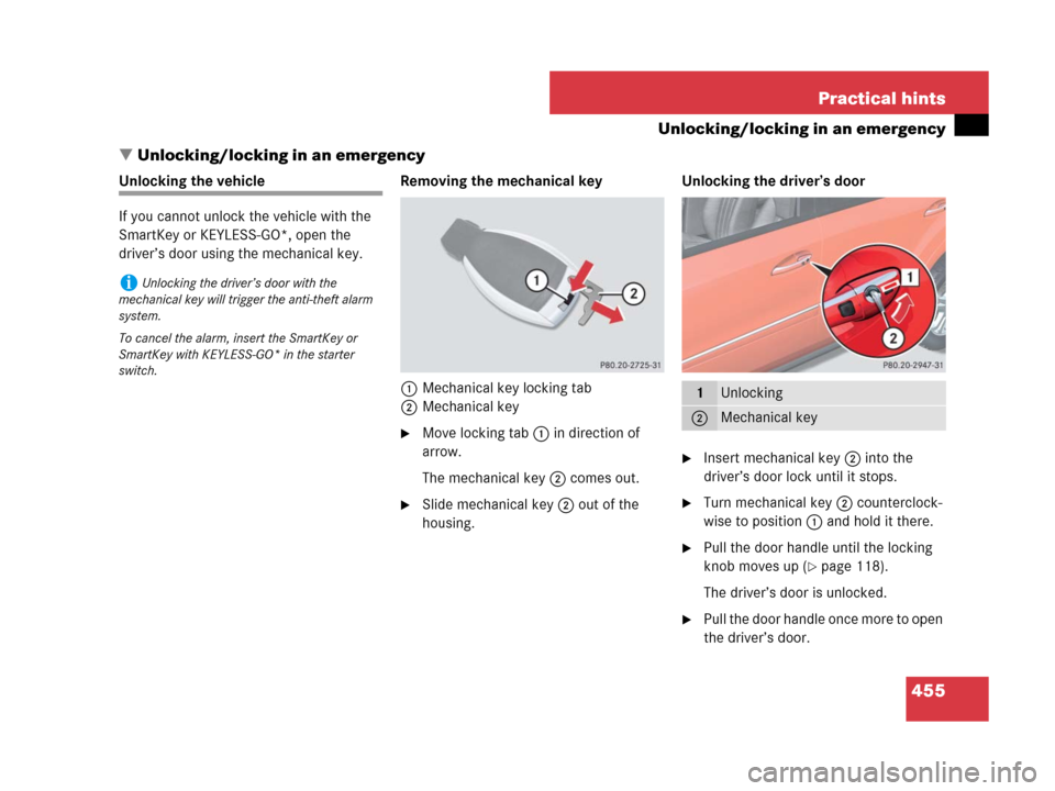
driver’s door using the mechanical key.Removing the mechanical key
1Mechanical key locking tab
2Mechanical key
�Move locking tab1 in direction of
arrow.
The mechanical key2 comes out.
�Slide mechanical key2 out of the
housing.Unlocking the driver’s door
�Insert mechanical key2 into the
driver’s door lock until it stops.
�Turn mechanical key2 counterclock-
wise to position1 and hold it there.
�Pull the door handle until the locking
knob moves up (
�page 118).
The driver’s door is unlocked.
�Pull the door handle once more to open
the driver’s door.
iUnlocking the driver’s door with the
mechanical key will trigger the anti-theft alarm
system.
To cancel the alarm, insert the SmartKey or
SmartKey with KEYLESS-GO* in the starter
switch.
1Unlocking
2Mechanical key
Page 468 of 561
467 Practical hints
Replacing bulbs
�Turn cover1 counterclockwise.
�Remove cover1.
�Turn bulb socket2 counterclockwise.
�Pull bulb socket2 out of the
headlamp housing.
�Pull the low beam bulb out of bulb
socket2.
�Insert the new low beam bulb into bulb
socket2.
�Insert bulb socket2 into the
headlamp housing.
�Turn bulb socket2 clockwise until it
engages.
�Place cover1 on the opening in the
headlamp housing.
�Turn cover1 clockwise until it engag-
es.Bi-Xenon* low beam/high beam
headlampHigh beam bulb (halogen headlamp)
1High beam headlamp cover
2Bulb socket for high beam headlamp
Warning!G
Do not remove the low beam/high beam
cover for the Bi-Xenon* headlamp. Because
of high voltage in Xenon* lamps, it is danger-
ous to replace the bulb or repair the lamp
and its components. We recommend that
you have such work done by a qualified
technician.
Page 469 of 561

468 Practical hints
Replacing bulbs
�Turn cover1 counterclockwise.
�Remove cover1.
�Turn bulb socket2 counterclockwise.
�Pull bulb socket2 out of the
headlamp housing.
�Pull the high beam bulb out of bulb
socket2.
�Insert the new high beam bulb into bulb
socket2.
�Insert bulb socket2 into the
headlamp housing.
�Turn bulb socket2 clockwise until it
engages.
�Place cover1 on the opening in the
headlamp housing.
�Turn cover1 clockwise until it engag-
es.Turn signal lamp bulb
1Bulb socket for turn signal lamp
�Turn bulb socket1 counterclockwise.
�Pull bulb socket1 out of the
headlamp housing.
�Pull the turn signal bulb out of bulb
socket1.
�Insert the new turn signal bulb into bulb
socket1.
�Insert bulb socket1 into the
headlamp housing.
�Turn bulb socket1 clockwise until it
engages.Parking and standing lamp bulb
�Turn bulb socket3 (�page 466)
counterclockwise.
�Pull bulb socket3 out of the
headlamp housing.
�Pull the bulb out of bulb socket3.
�Insert the new bulb into bulb
socket3.
�Insert bulb socket3 into the
headlamp housing.
�Turn bulb socket3 clockwise until it
engages.
Page 470 of 561

counterclockwise.
�Pull bulb socket5 out of the
headlamp housing.
�Pull the side marker bulb out of bulb
soc")
469 Practical hints
Replacing bulbs
Side marker lamp bulb
�Turn bulb socket5 (�page 466)
counterclockwise.
�Pull bulb socket5 out of the
headlamp housing.
�Pull the side marker bulb out of bulb
socket5.
�Insert the new side marker bulb into
bulb socket5.
�Insert bulb socket5 into the
headlamp housing.
�Turn bulb socket5 clockwise until it
engages.Front fog lamp bulbs
Removing front fog lamp cover:
1Cover
2Front fog lamp or corner-illuminating
front fog lamp*
�Insert a suitable object (e.g. screwdriv-
er) at point indicated by the arrow and
pry out cover1.
Cover1 is released.
�Swing cover1 outwards and take it
off.
Removing front fog lamp cover (Vehicles
with AMG Sport Package* or ML 63 AMG):
1Cover
2Front fog lamp
�Use a suitable object (e.g. hook or a
screwdriver) and place the hook or
screwdriver carefully between lower
end of cover and bumper.
!If not done carefully and properly, damage
to the bumper can result. We therefore recom-
mend that you have this work carried out by an
authorized Mercedes-Benz Light Truck Center.
��