Page 513 of 601
512 Practical hints
Replacing bulbs
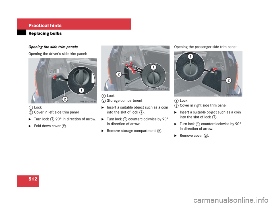
Opening the side trim panels
Opening the driver’s side trim panel:
1Lock
2Cover in left side trim panel
�Turn lock1 90° in direction of arrow.
�Fold down cover2.1Lock
2Storage compartment
�Insert a suitable object such as a coin
into the slot of lock1.
�Turn lock1 counterclockwise by 90°
in direction of arrow.
�Remove storage compartment2.Opening the passenger side trim panel:
1Lock
2Cover in right side trim panel
�Insert a suitable object such as a coin
into the slot of lock1.
�Turn lock1 counterclockwise by 90°
in direction of arrow.
�Remove cover2.
164.boo Seite 512 Freitag, 30. März 2007 12:54 12
Page 514 of 601
513 Practical hints
Replacing bulbs
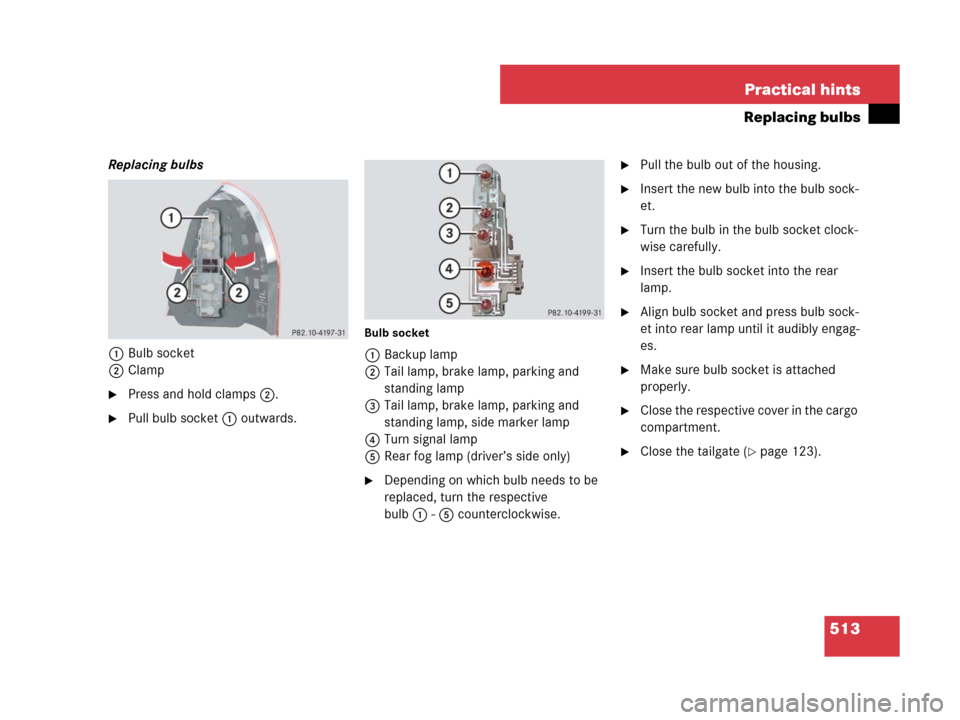
Replacing bulbs
1Bulb socket
2Clamp
�Press and hold clamps2.
�Pull bulb socket1 outwards.
Bulb socket
1Backup lamp
2Tail lamp, brake lamp, parking and
standing lamp
3Tail lamp, brake lamp, parking and
standing lamp, side marker lamp
4Turn signal lamp
5Rear fog lamp (driver’s side only)
�Depending on which bulb needs to be
replaced, turn the respective
bulb1-5 counterclockwise.
�Pull the bulb out of the housing.
�Insert the new bulb into the bulb sock-
et.
�Turn the bulb in the bulb socket clock-
wise carefully.
�Insert the bulb socket into the rear
lamp.
�Align bulb socket and press bulb sock-
et into rear lamp until it audibly engag-
es.
�Make sure bulb socket is attached
properly.
�Close the respective cover in the cargo
compartment.
�Close the tailgate (�page 123).
164.boo Seite 513 Freitag, 30. März 2007 12:54 12
Page 516 of 601
515 Practical hints
Replacing bulbs
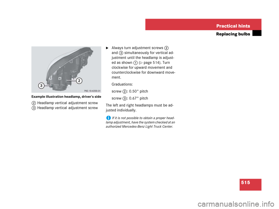
Example illustration headlamp, driver’s side
2Headlamp vertical adjustment screw
3Headlamp vertical adjustment screw
�Always turn adjustment screws2
and3 simultaneously for vertical ad-
justment until the headlamp is adjust-
ed as shown1 (
�page 514). Turn
clockwise for upward movement and
counterclockwise for downward move-
ment.
Graduations:
screw2:0.50° pitch
screw3:0.67° pitch
The left and right headlamps must be ad-
justed individually.
iIf it is not possible to obtain a proper head-
lamp adjustment, have the system checked at an
authorized Mercedes-Benz Light Truck Center.
164.boo Seite 515 Freitag, 30. März 2007 12:54 12
Page 519 of 601
518 Practical hints
Replacing wiper blades
Removing
�Remove the SmartKey from the starter
switch.
Vehicles with KEYLESS-GO*:
�Make sure the vehicle’s on-board
electronics have status0
(
�page 44).
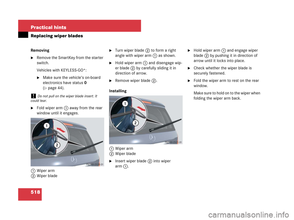
�Fold wiper arm1 away from the rear
window until it engages.
1Wiper arm
2Wiper blade
�Turn wiper blade2 to form a right
angle with wiper arm1 as shown.
�Hold wiper arm1 and disengage wip-
er blade2 by carefully sliding it in
direction of arrow.
�Remove wiper blade2.
Installing
1Wiper arm
2Wiper blade
�Insert wiper blade2 into wiper
arm1.
�Hold wiper arm1 and engage wiper
blade2 by pushing it in direction of
arrow until it locks into place.
�Check whether the wiper blade is
securely fastened.
�Fold the wiper arm to rest on the rear
window.
Make sure to hold on to the wiper when
folding the wiper arm back.
!Do not pull on the wiper blade insert. It
could tear.
164.boo Seite 518 Freitag, 30. März 2007 12:54 12
Page 521 of 601
.
�Take the wheel wrench, the collapsible
wheel chock, and the vehicle jack")
520 Practical hints
Flat tire
Mounting the spare wheel
Preparing the vehicle
�Prepare the vehicle as described
(
�page 519).
�Take the wheel wrench, the collapsible
wheel chock, and the vehicle jack out
of the cargo compartment
(
�page 490).
�Take the Minispare wheel out of the
cargo compartment (
�page 495).Lifting the vehicle
!Depending on vehicle production date your
vehicle may be equipped with a scissors-type
jack (located under the cargo compartment
floor). If so equipped, only use this jack when
jacking up the vehicle as otherwise the vehicle’s
underbody can be damaged. See separate
instructions for scissors-type jack.
Warning!G
When jacking up the vehicle, only use the
jack which has been specifically approved
by Mercedes-Benz for your vehicle.
The jack is designed exclusively for jacking
up the vehicle at the jack take-up brackets
built into both sides of the vehicle. Make
sure the jack arm is fully seated in the jack
take-up bracket.
The jack is intended only for lifting the
vehicle briefly for wheel changes. It is not
suited for performing maintenance work
under the vehicle. To help avoid personal in-
jury, use the jack only to lift the vehicle dur-
ing a wheel change.
Never get beneath the vehicle while it is sup-
ported by the jack. Keep hands and feet
away from the area under the lifted vehicle.
Always lower the vehicle onto sufficient
capacity jackstands before working under
the vehicle.
Always firmly set parking brake and block
wheels with wheel chocks or other sizeable
objects before raising vehicle with jack. Do
not disengage parking brake while the vehi-
cle is raised.
Make sure that the ground on which the ve-
hicle is standing and where you place the
jack is solid, level and not slippery. If neces-
sary, use a large underlay. On slippery sur-
faces, such as tiled floors, you should use a
non-slip underlay, for example a rubber mat.
Do not use wooden blocks or similar objects
to support the jack. Otherwise the jack may
not be able to achieve its load-bearing ca-
pacity if it is not at its full height.
Never start the engine when the vehicle is
raised.
Also observe the notes on the jack.
164.boo Seite 520 Freitag, 30. März 2007 12:54 12
Page 522 of 601

521 Practical hints
Flat tire
�Prevent the vehicle from rolling away
by blocking wheels with wheel chocks
or other sizeable objects.
One collapsible wheel chock is includ-
ed with the vehicle tool kit
(
�page 490). For information on set-
ting up the collapsible wheel chock,
see (
�page 494).Changing wheel on a level surface
Changing rear wheel on passenger side
(Example illustration)
�Place the wheel chock in front of and
another sizeable object behind the
wheel that is diagonally opposite to the
wheel being changed.Changing wheel on a slight decline
Always try lifting the vehicle using the jack
on a level surface. However, should
circumstances require you to do so on a
slight decline, place the wheel chock and
another sizeable object as follows:
Changing wheel on passenger side
(Example illustration)
�Place wheel chock (or another sizeable
object) in front of both wheels on the
side opposite to the side on which the
wheel is to be changed.
Warning!G
Only jack up the vehicle on level ground or
on slight inclines/declines. Otherwise, the
vehicle could fall off the jack and injure you
or others.
164.boo Seite 521 Freitag, 30. März 2007 12:54 12
Page 525 of 601
524 Practical hints
Flat tire
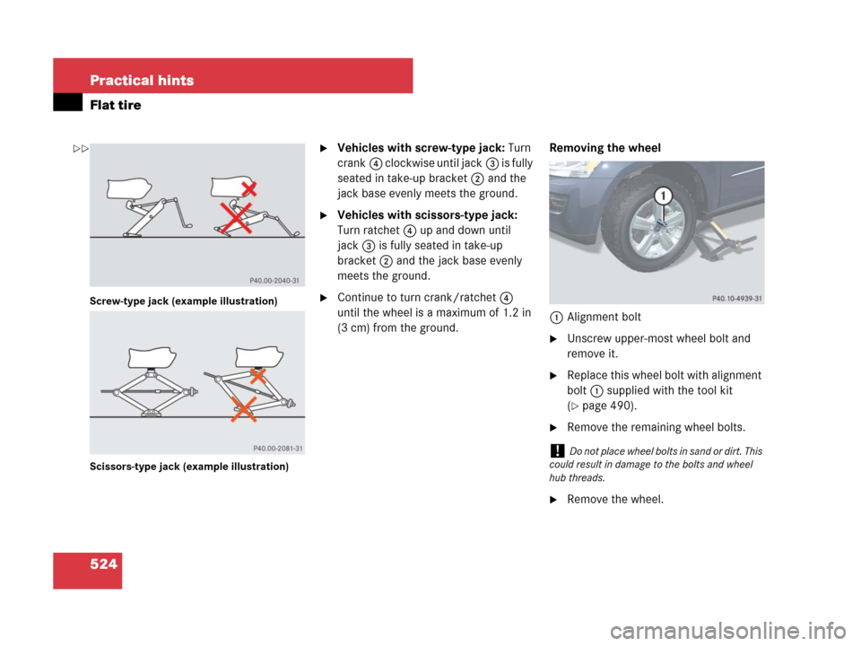
Screw-type jack (example illustration)
Scissors-type jack (example illustration)
�Vehicles with screw-type jack: Turn
crank4 clockwise until jack3 is fully
seated in take-up bracket2 and the
jack base evenly meets the ground.
�Vehicles with scissors-type jack:
Turn ratchet4 up and down until
jack3 is fully seated in take-up
bracket2 and the jack base evenly
meets the ground.
�Continue to turn crank/ratchet4
until the wheel is a maximum of 1.2 in
(3 cm) from the ground.Removing the wheel
1Alignment bolt
�Unscrew upper-most wheel bolt and
remove it.
�Replace this wheel bolt with alignment
bolt1 supplied with the tool kit
(
�page 490).
�Remove the remaining wheel bolts.
�Remove the wheel.
!Do not place wheel bolts in sand or dirt. This
could result in damage to the bolts and wheel
hub threads.
��
164.boo Seite 524 Freitag, 30. März 2007 12:54 12
Page 527 of 601

526 Practical hints
Flat tire
Lowering the vehicle
�Vehicles with scissors-type jack:
Attach ratchet to vehicle jack in such a
way that the wordDOWN can be seen.
�Lower the vehicle until its resting fully
on its own weight.
�Vehicles with screw-type jack:
Turn crank counterclockwise.
�Vehicles with scissors-type jack:
Turn ratchet in Direction of DOWN.
�Remove the jack.
1-5Wheel bolts
�Tighten the five wheel bolts evenly, fol-
lowing the diagonal sequence illustrat-
ed (1 to 5), until all bolts are tight.
Observe a tightening torque of
110 lb-ft (150 Nm).
�Store jack and all other vehicle tool kit
items back into the storage well.
Warning!G
Have the tightening torque checked after
changing a wheel. The wheels could come
loose if they are not tightened to a torque of
110 lb-ft (150 Nm).
iThe removed road wheel cannot be stored in
the spare wheel well under the cargo compart-
ment floor, but should be transported in the car-
go compartment wrapped in a protective cover.
Vehicles with TPMS or Advanced TPMS*:
Do not activate the tire inflation pressure moni-
tor until a full size wheel/tire with functioning
sensor has been placed back into service on the
vehicle.
164.boo Seite 526 Freitag, 30. März 2007 12:54 12