Page 427 of 509
426 Practical hints
Unlocking/locking in an emergency
Fuel filler flap
�Open the fuse box in the trunk
(
�page 458).
1Release cable
�Pull on the release cable1.
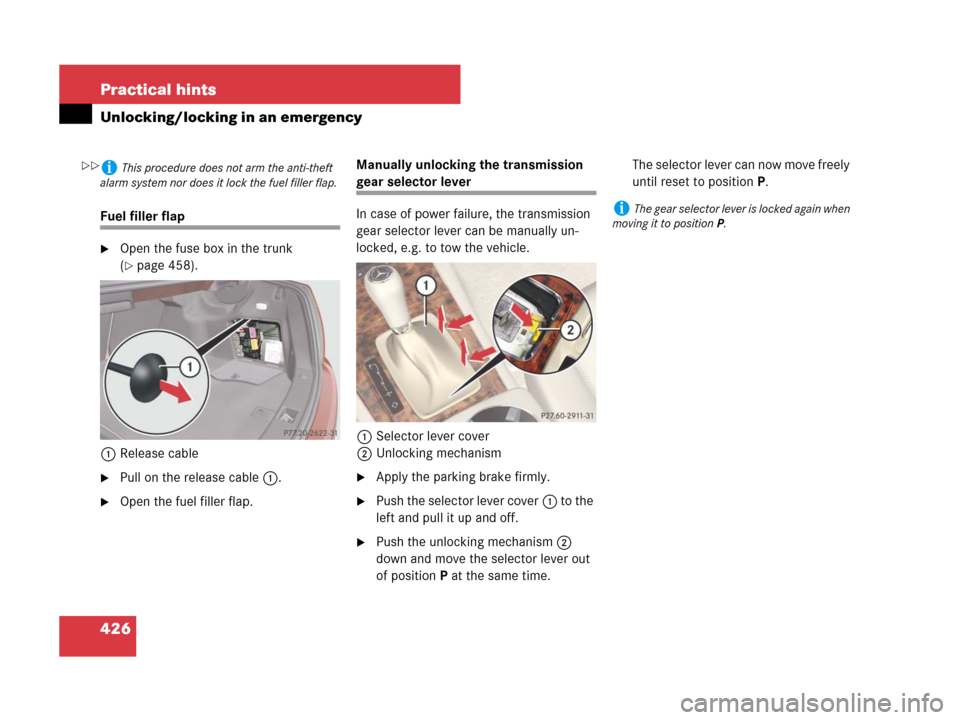
�Open the fuel filler flap.Manually unlocking the transmission
gear selector lever
In case of power failure, the transmission
gear selector lever can be manually un-
locked, e.g. to tow the vehicle.
1Selector lever cover
2Unlocking mechanism
�Apply the parking brake firmly.
�Push the selector lever cover1 to the
left and pull it up and off.
�Push the unlocking mechanism2
down and move the selector lever out
of positionP at the same time.The selector lever can now move freely
until reset to positionP.
iThis procedure does not arm the anti-theft
alarm system nor does it lock the fuel filler flap.
iThe gear selector lever is locked again when
moving it to positionP.
��
Page 432 of 509
431 Practical hints
Replacing bulbs
Bulbs Front lamps Rear lamps
LampType
1Additional turn signal
lampLED
2Turn signal lampPY 21 W
3Halogen headlamp:
Low beam
Bi-Xenon* headlamp:
Low and high beam
1
1Regarding vehicles with Bi-Xenon headlamps*, do
not replace the Bi-Xenon bulbs yourself.
H7 (55 W)
D1S-35 W
4Halogen headlamp:
High beam/high beam
flasher
Bi-Xenon* headlamp:
High beam flasher
H7 (55 W)
H7 (55 W)
5Front fog lamp
Corner-illuminating
front fog lamp*H11 (55 W)
H11 (55 W)
6Side marker lampW 5 W
7Parking and standing
lamp2 x
W5W-BV
LampType
8High mounted brake
lampLED
9Side markerW 5 W
aTurn signal lampPY 21 W
bBrake lamp, parking
and standing lamp, tail
lamp2 x P 21 W
cBackup lampP 21 W
dLicense plate lampsW 5 W
eRear fog lamp
(driver’s side only),
Side markerP 21 W
W 5 W
Page 433 of 509

432 Practical hints
Replacing bulbs
Notes on bulb replacement
�Only use 12 volt bulbs of the same type
and with the specified watt rating.
�Switch lights off before changing a bulb
to prevent short circuits.
�Always use a clean lint-free cloth when
handling bulbs.
�Your hands should be dry and free of oil
and grease.
�If the newly installed bulb does not
come on, visit an authorized
Mercedes-Benz Center.Have the LEDs and bulbs for the following
lamps replaced at an authorized
Mercedes-Benz Center.
�Additional turn signal lamps in the exte-
rior rear view mirrors
�High mounted brake lamp
�Bi-Xenon* lamps
�Front fog lamps
�Front side marker lamps
�License plate lamps
Replacing bulbs for front lamps
Before you start to replace a bulb for a
front lamp, do the following first:
�Turn the exterior lamp switch to
positionM (
�page 108).
�Open the hood (�page 325).
Warning!G
Keep bulbs out of reach of children.
Bulbs and bulb sockets can be very hot. Al-
low the lamp to cool down before changing
a bulb.
Halogen lamps contain pressurized gas. A
bulb can explode if you:
�touch or move it when hot
�drop the bulb
�scratch the bulb
Wear eye and hand protection.
Because of high voltage in Xenon lamps, it is
dangerous to replace the bulb or repair the
lamp and its components. We recommend
that you have such work done by a qualified
technician.!Do not replace the LEDs yourself. You could
otherwise damage the LEDs or parts of the
vehicle. Only have the LEDs replaced at an au-
thorized Mercedes-Benz Center.
Page 438 of 509

437 Practical hints
Replacing bulbs
Tail lamp unit
�Open trunk lid.
�For driver side: Lift up the bottom and
pull out the trim panel covering the
driver side rear light.
�For passenger side: Open the fuse box
in the trunk (
�page 458).
1Tabs
2Connector
�Disconnect electrical connector2.
�Pull tabs1 in direction of arrows.
�Remove the bulb carrier.1Side marker lamp
2Rear fog lamp (driver’s side)/Side
marker lamp
3Backup lamp
4Brake lamp/tail lamp
5Parking and standing lamp, brake
lamp/tail lamp
6Turn signal lamp
�Press gently onto the respective bulb
and turn counterclockwise out of its
bulb socket.
Side marker lamp1: Turn the bulb
socket on backside of tail lamp unit
counterclockwise and removes side
marker lamp1 with bulb socket
�Press the new bulb gently into its bulb
socket and turn clockwise until it
engages.
Side marker lamp1: Turn the new
bulb with socket on backside of tail
lamp unit clockwise until it engages.
�Reinstall the bulb carrier.
Let tabs1 (
�page 437) engage.
�Connect the electrical connector2
(
�page 437) until it engage.
�Reinstall trim panel.
License plate lamp
Since replacing the license plate lamp
bulbs is a technically highly demanding
process, we recommend you have the li-
cense plate lamp bulbs replaced at an au-
thorized Mercedes-Benz Center.
Page 441 of 509

440 Practical hints
Flat tire
Preparing the vehicle
�Park the vehicle in a safe distance from
moving traffic on a hard, flat surface
when possible.
�Turn on the hazard warning flashers.
�Turn the steering wheel so that the
front wheels are in a straight-ahead
position.
�Set the parking brake.
�Vehicles with automatic transmission*:
Move the gear selector lever to
positionP (
�page 138).
�Turn off the engine (�page 134).
�Remove the SmartKey from the starter
switch.
Vehicles with KEYLESS-GO*:
�Turn off the engine by pressing the
KEYLESS-GO* button once
(
�page 135).
�Open the driver’s door (this puts
the starter switch in position0,
same as with the SmartKey re-
moved from the starter switch). The
driver’s door then can be closed
again.
�Have any passenger exit the vehicle at
a safe distance from the roadway.
Warning!G
The dimensions of the Minispare wheel are
different from those of the road wheels. As
a result, the vehicle handling characteristics
change when driving with a Minispare wheel
mounted. Adapt your driving style
accordingly.
The Minispare wheel is for temporary use
only. When driving with Minispare wheel
mounted, ensure proper tire inflation
pressure and do not exceed a vehicle speed
of 50 mph (80 km/h).
Contact the nearest Mercedes-Benz Center
as soon as possible to have the Minispare
wheel replaced with a regular road wheel.
Never operate the vehicle with more than
one Minispare wheel mounted.
Do not switch off the ESP
® with a Minispare
wheel mounted.
iOpen the door only when conditions are safe
to do so.
Page 442 of 509
.
�Take vehicle tool kit tray and vehicle
jack out of trunk (
�page 420")
441 Practical hints
Flat tire
Mounting the Minispare wheel
Preparing the vehicle
�Prepare the vehicle as described
(
�page 440).
�Take vehicle tool kit tray and vehicle
jack out of trunk (
�page 420).
�Take the Minispare wheel from the
wheel well under the trunk floor
(
�page 422).Lifting the vehicle
Warning!G
When jacking up the vehicle, only use the
jack which has been specifically approved
by Mercedes-Benz for your vehicle.
The jack is designed exclusively for jacking
up the vehicle at the jack take-up brackets
built into both sides of the vehicle. Make
sure the jack arm is fully seated in the jack
take-up bracket.
The jack is intended only for lifting the
vehicle briefly for wheel changes. It is not
suited for performing maintenance work
under the vehicle. To help avoid personal
injury, use the jack only to lift the vehicle
during a wheel change.
Never get beneath the vehicle while it is sup-
ported by the jack. Keep hands and feet
away from the area under the lifted vehicle.
Always lower the vehicle onto sufficient
capacity jackstands before working under
the vehicle.
Always firmly set the parking brake and
block wheels with wheel chocks or other
sizeable objects before raising vehicle with
jack. Do not release the parking brake while
the vehicle is raised.
Make sure that the ground on which the
vehicle is standing and where you place the
jack is solid, level and not slippery. If neces-
sary, use a large underlay. On slippery
surfaces, such as tiled floors, you should
use a non-slip underlay, for example a
rubber mat.
Do not use wooden blocks or similar objects
to support the jack. Otherwise the jack may
not be able to achieve its load-bearing
capacity if it is not at its full height.
Be certain that the jack is always vertical
(plumb line) when in use, especially on hills.
Always try to use the jack on level surface.
Never start the engine when the vehicle is
raised.
Also observe the notes on the jack.
Page 449 of 509
.
�Make sure gear selector l")
448 Practical hints
Battery
Starter battery
1Battery
2Positive terminal
3Negative terminal
4Ventilation hose
Disconnecting the battery
�Apply the parking brake (�page 134).
�Make sure gear selector lever* is set to
positionP (manual transmission to
Neutral).
�Turn off all electrical consumers.
�Remove SmartKey from starter switch.Vehicles with KEYLESS-GO* (Canada
only):
�Press the start / stop button until
the engine shuts off.
�Open the driver’s door.
�Open the hood (�page 325).
�Remove the filter box (�page 447).
�Read and observe safety instructions
and precautions (
�page 446).
�Disconnect the battery negative lead
from negative terminal3.
�Remove cover from the positive
terminal2.
�Disconnect the battery positive lead.iIf the battery is discharged, you must use
the mechanical key to unlock (
�page 424) or
lock (
�page 425) the vehicle.
Warning!G
With a disconnected battery
�you will no longer be able to turn the
SmartKey in the starter switch and
pressing the KEYLESS-GO* start/stop
button (Canada only) will have no effect
�vehicles with automatic transmission*:
the gear selector lever will remain
locked in positionP
!Always disconnect the starter battery in the
order described below. You could otherwise
damage the vehicle’s electronics.
Page 453 of 509

452 Practical hints
Jump starting
The battery is located in the engine com-
partment on the right hand side. For jump
starting, use the under hood terminals in
front of the battery.
�Make sure the two vehicles do not
touch.
�Turn off all electrical consumers,
except hazard warning flashers or work
lights.
�Apply the parking brake (�page 134).
�Make sure gear selector lever* is set to
positionP (manual transmission to
Neutral).
�Open the hood (�page 326).
�Slide red cover2 from positive under
hood terminal3 in direction of arrow. 1Positive terminal of charged battery
2Positive under hood terminal cover
3Positive under hood terminal in front of
discharged battery
4Negative under hood terminal
5Negative terminal of charged battery
�Connect positive terminal1 of the
charged battery with positive under
hood terminal3 in front of the dis-
charged battery with the jumper cable.
Clamp cable to charged battery1
first.
�Start the engine of the vehicle with the
charged battery and run at idle speed.
�Connect negative terminal5 of the
charged battery to jumper cables and
attach other end to negative under
hood terminal4 on the vehicle. Clamp
cable to charged battery5 first
�Start the engine of the disabled
vehicle.
You can now turn on the electrical con-
sumers. Do not switch on the headlamps
under any circumstances.
�Remove the jumper cables first from
the negative terminals4 and5 and
then from the positive terminals3
and1.
You can now switch on the headlamps.
�Slide red cover2 from positive under
hood terminal3 back.
�Close the hood (�page 326).
�Have the battery checked at the near-
est authorized Mercedes-Benz Center.
!Never invert the terminal connections.