2008 MERCEDES-BENZ A-CLASS HATCHBACK load capacity
[x] Cancel search: load capacityPage 15 of 305

12Centre console.
.............................. 160
Glove compartment. .......................160
Luggage compartment. ...................161
Stowage space
Cup holder ...................................... 144
Submenu (on-board computer)......... 107
Convenience ................................... 108
Instrument cluster .......................... 107
Lighting........................................... 108
Time/date. ..................................... 107
Vehicle............................................ 108
Summer opening
see Convenience opening
Sun visor............................................. 162
Supplemental Restraint System see SRS
Surround lighting
Switching on/off (on-board com-
puter). ............................................. 110
Switching off the alarm
ATA. .................................................. 57T
Tailgate Display message ............................. 212
Opening/closing. .............................. 62
Tail lamps
changing. ........................................ 250Tank
see Fuel tank
Tank capacity..................................... 292
Technical data Acceleration. .................................. 281
Engine............................................ .278
Speed. ............................................ 280
Trailer loads .................................... 291
Tyres. .............................................. 283
Vehicle dimensions. ........................286
Vehicle weights............................... 286
Wheels. ........................................... 283
Telephone
see Mobile phone
Telephone compartment................... 160
Temperature Coolant. ............................................ 97
Outside temperature......................... 98
Thermotronic
Malfunction indicator lamp. ............222
Third brake lamp
Display message ............................. 217
Through-loading................................. 147
Tightening torque............................... 262
Time Setting (on-board computer).......... .109
Setting the time (on-board com-
puter). ............................................. 109
TIREFIT kit
Using. ............................................. 253TopTether..............................................
49
Total distance recorder............... 26, 100
Tow-away protection........................... 58
Towing................................................. 269
Towing eye Fitting ............................................. 269
Removing....................................... .270
Tow-starting ........................................ 270
Trailer 7-pin connector .............................. 191
Display message ............................. 216
Power supply. ................................. 190
Trailer loads
Technical data. ............................... 291
Trailer tow hitch
Notes on care ................................. 196
Trailer towing
Active parking assist .......................127
Driving tips ..................................... 188
Malfunction..................................... 240
Mounting dimensions .....................290
Parktronic. ...................................... 123
Transmission
Display message ............................. 209
Transmission output (maximum)
Telephone/two-way radio ...............275
Transport (vehicle)............................. 270
Trip computer Menu (on-board computer). ............112 Index
169_AKB; 2; 4, en-GB
wdomann,
Version: 2.10.6
2008-07-16T08:52:06+02:00 - Seite 12 Dateiname: 6515_0315_02_buchblock.pdf; preflight
Page 149 of 305

Loading and stowing
146
R
Always place the load against the rear seat
backrests or the seat cushions if these
have been folded forwards.
R The maximum load capacity of the stowage
well under the luggage compartment floor
is 25 kg.
R Always place the load behind unoccupied
seats if possible.
R Secure the load with sufficiently strong and
wear-resistant load restraints. Pad sharp
edges for protection.
i Load restraints are available at any quali-
fied specialist workshop, e.g. a Mercedes-
Benz Service Centre. R
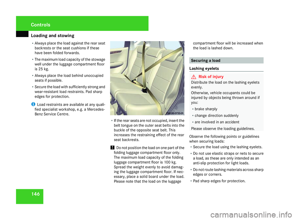
If the rear seats are not occupied, insert the
belt tongue on the outer seat belts into the
buckle of the opposite seat belt. This
increases the restraining effect of the rear
seat backrests.
! Do not position the load on one part of the
folding luggage compartment floor only.
The maximum load capacity of the folding
luggage compartment floor is 100 kg.
Spread the weight evenly to avoid damag-
ing the luggage compartment floor. If nec-
essary, place a solid board under the load.
Please note that the load on the luggage compartment floor will be increased when
the load is lashed down. Securing a load
Lashing eyelets G
Risk of injury
Distribute the load on the lashing eyelets
evenly.
Otherwise, vehicle occupants could be
injured by objects being thrown around if
you:
R brake sharply
R change direction suddenly
R are involved in an accident
Please observe the loading guidelines.
Observe the following points or guidelines
when securing loads:
R Secure the load using the lashing eyelets.
R Do not use elastic straps or nets to secure
a load, as these are only intended as an
anti-slip protection for light loads.
R Do not route lashing materials across sharp
edges or corners.
R Pad sharp edges for protection. Controls
169_AKB; 2; 4, en-GB
wdomann,
Version: 2.10.6 2008-07-16T08:52:06+02:00 - Seite 146Dateiname: 6515_0315_02_buchblock.pdf; preflight
Page 153 of 305

Loading and stowing
150 Enlarging the luggage compartment
The left-hand and right-hand rear seats can
be folded down to increase the luggage com-
partment capacity. G
Risk of injury
Make sure that nobody can become trap-
ped as you fold the backrests forward.
! To prevent damage, before the backrests
are folded forward:
R the head restraints must be pushed in
fully
R the front seats must be as far forwards
as possible
R the seat cushions must be folded forward
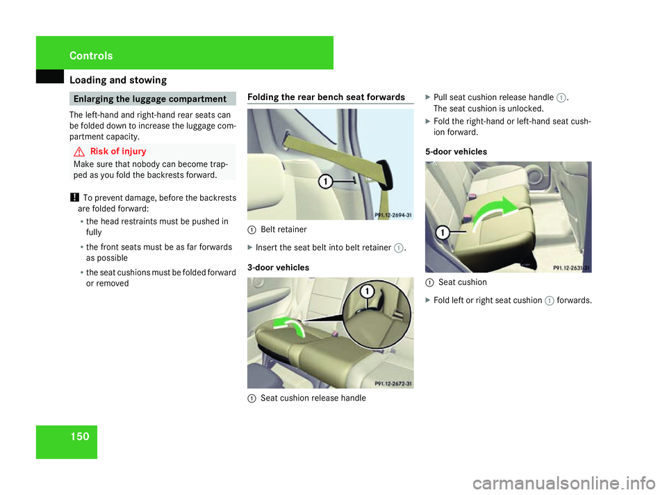
or removed Folding the rear bench seat forwards 1
Belt retainer
X Insert the seat belt into belt retainer 1.
3-door vehicles 1
Seat cushion release handle X
Pull seat cushion release handle 1.
The seat cushion is unlocked.
X Fold the right-hand or left-hand seat cush-
ion forward.
5-door vehicles 1
Seat cushion
X Fold left or right seat cushion 1forwards. Controls
169_AKB; 2; 4, en-GB
wdomann,
Version: 2.10.6
2008-07-16T08:52:06+02:00 - Seite 150 Dateiname: 6515_0315_02_buchblock.pdf; preflight
Page 157 of 305

Loading and stowing
154
X
Place the backrest, starting with the front
seat feet, onto the locking bolts in recesses
1. 2
Red lock verification indicator
X Swing the backrest back until it engages.
Red lock verification indicator 2is no lon-
ger visible.
X Make sure that the lever is lying flat on the
vehicle floor.
X Take the connector out of the recesses on
the vehicle floor.
X Insert the connector back into the lever
until you hear it engage.
i Make sure that you insert the connector
correctly into the lever, as the rear seat belt
status will otherwise no longer be displayed
in the instrument cluster. X
Fit the seat cushions as required.
X Swing the seat cushion backwards.
X Adjust the head restraints if necessary .
If red lock verification indicator 2is visible,
this means the backrest is not engaged. G
Risk of injury
Make sure that the backrest is correctly
locked in position. The red lock verification
indicators on the left and right sides should
no longer be visible. If they are visible, the
backrests are not locked in position.
Occupants could then be injured in the
event of an accident, e.g. by objects being
thrown forwards from the luggage com-
partment.
X Fold back the seat cushion. Stowage well under the luggage com-
partment floor
The maximum load capacity of the stowage
well under the luggage compartment floor is
25 kg. G
Risk of injury
You should always close the luggage com-
partment floor if you are transporting
objects in the stowage well under the lug-
gage compartment floor.
Otherwise, you and other vehicle occu-
pants could be injured by objects being
thrown around the vehicle in the event of
sharp braking, a sudden change in direction
or an accident.
Removing/fitting the luggage compart-
ment floor (3-door vehicles without var-
iable luggage compartment floor) You can remove the luggage compartment
floor to enable you to load and unload the
stowage well more easily.
X
To remove: raise the luggage compart-
ment floor to an angle of approximately
45°.
X Remove the luggage compartment floor. Controls
169_AKB; 2; 4, en-GB
wdomann
, Version: 2.10.6
2008-07-16T08:52:06+02:00 - Seite 154 Dateiname: 6515_0315_02_buchblock.pdf; preflight
Page 263 of 305

Flat tyre
2601
Wheel wrench
X Using wheel wrench 1, loosen the bolts on
the wheel you wish to change by about one
full turn. Do not unscrew the bolts com-
pletely.
Raising the vehicle G
Risk of injury
The jack is designed only to raise the vehi-
cle for a short time while a wheel is being
changed.
The vehicle must be placed on stands if you
intend to work under it.
Make sure that the jack is placed on a firm,
non-slip, level surface. Do not use wooden
blocks or similar objects as a jack underlay. Otherwise, the jack will not be able to ach-
ieve its load-bearing capacity due to the
restricted height.
Do not start the engine at any time while
the wheel is being changed.
Do not lie under the vehicle when it is being
supported by the jack. If you do not raise
the vehicle as described, it could slip off the
jack (e.g. if the engine is started or a door
or the tailgate is opened or closed) and you
could be seriously injured. G
Risk of accident
If you fail to position the jack correctly, the
vehicle may:
R slip off the jack
R injure you or others
R be damaged
Thus, it is important to make sure that the
jack is positioned correctly in the respec-
tive jacking points. Before positioning the
jack, remove any dirt that may have collec-
ted in the jacking points.
The jacking points for the jack are located
behind the wheel housings of the front wheels
and in front of the wheel housings of the rear
wheels. 1
Jacking point
2 Jack
3 Ratchet ring spanner with socket wrench
X Position jack 2at jacking point 1. Practical advice
169_AKB; 2; 4, en-GB
wdomann,
Version: 2.10.6
2008-07-16T08:52:06+02:00 - Seite 260 Dateiname: 6515_0315_02_buchblock.pdf; preflight