Page 49 of 466

WARNING!
Position the shoulder belt height adjusters so that the
belt rests across the middle of your shoulder. Failure
to adjust the safety belt properly could reduce the
effectiveness of the seat belt and increase the risk of
injury in a collision.
As a guide, if you are shorter than average, you will
prefer a lower position, and if you are taller than average,
you’ll prefer a higher position. When you release the
anchorage, try to move it up or down to make sure that
it is locked in position.
Seat Belt Pretensioners
The driver and front passenger seat belts are equipped
with a pretensioning device that is designed to remove
any slack from the seat belt systems in the event of a
collision. This device improves the performance of the
seat belt by assuring that the belt is tight around the
occupant early in a collision. Pretensioners work for all
size occupants, including those in child restraints.
NOTE: These devices are not a substitute for proper seat
belt placement by the occupant. The seat belt must still be
worn snugly and positioned properly.
The pretensioners are triggered by the Occupant Re-
straint Control (ORC) Module. Like the front airbags, the
pretensioners are a single use item. After a collision that
is severe enough to deploy the airbags and pretensioners,
they must be replaced.
48 THINGS TO KNOW BEFORE STARTING YOUR VEHICLE
Page 65 of 466

WARNING!
•Improper installation can lead to failure of an
infant or child restraint. It could come loose in a
collision. The child could be badly injured or
killed. Follow the manufacturer’s directions ex-
actly when installing an infant or child restraint.
•A rearward facing infant restraint should only be
used in a rear seat. A rearward facing infant
restraint in the front seat may be struck by a
deploying passenger airbag which may cause se-
vere or fatal injury to the infant.
Here are some tips for getting the most out of your child
restraint:
•Before buying any restraint system, make sure that it
has a label certifying that it meets all applicable Safety Standards. The manufacturer also recommends that
you try a child restraint in the vehicle seats where you
will use it before you buy it.
•The restraint must be appropriate for your child’s
weight and height. Check the label on the restraint for
weight and height limits.
•Carefully follow the instructions that come with the
restraint. If you install the restraint improperly, it may
not work when you need it.
•All seating positions (except for driver) have a auto-
matic locking retractor identified by a distinctive label.
The seat belts are designed to keep the lap portion
tight around the child restraint so that it is not
necessary to use a locking clip. For the seat belt with
the automatic locking retractor, pull the belt from the
retractor until there is enough to allow you to pass
through the child restraint and slide the latch plate
into the buckle. Then, pull the belt until it is fully
64 THINGS TO KNOW BEFORE STARTING YOUR VEHICLE
Page 80 of 466
UNDERSTANDING THE FEATURES OF YOUR VEHICLE
CONTENTS
�Mirrors ...............................83
▫ Inside Day/Night Mirror .................83
▫ Outside Mirrors .......................84
� Hands–Free Communication (UConnect�) ......85
� Seats .................................86
▫ Front Seat Adjustment ...................86
▫ Manual Seat Height Adjustment
— If Equipped ........................87
▫ Front Seatback Recline ...................87 ▫
Front Easy Entry Seats (Two-Door Models) ....88
▫ Head Restraints .......................89
▫ Fold And Tumble Rear Seat
(Two-Door Models) .....................89
▫ Removing The Rear Seat
(Two-Door Models) .....................91
▫ Replacing The Rear Seat
(Two-Door Models) .....................92
▫ 60/40 Split Folding Rear Seat
(Four-Door Models) ....................92
3
Page 88 of 466
Manual Seat Height Adjustment — If Equipped
The driver’s seat height can be raised or lowered by using
the ratcheting handle on the outboard side of the seat.
Pull upward on the handle to raise the seat. Push
downward on the handle to lower the seat.
Front Seatback Recline
To recline:
1. Lean forward before lifting the handle, then lean back
to the desired position and release the handle.
2. Lift the handle to return the seatback to an upright
position.
Seat Height AdjustmentRecline Lever
UNDERSTANDING THE FEATURES OF YOUR VEHICLE 87
3
Page 222 of 466

Two Types of Signals
There are two basic types of radio signals: AM or
Amplitude Modulation, in which the transmitted sound
causes the amplitude, or height, of the radio waves to
vary; and FM or Frequency Modulation, in which the
frequency of the wave is varied to carry the sound.
Electrical Disturbances
Radio waves may pick up electrical disturbances during
transmission. They mainly affect the wave amplitude,
and thus remain a part of the AM reception. They
interfere very little with the frequency variations that
carry the FM signal.
AM Reception
AM sound is based on wave amplitude, so AM reception
can be disrupted by such things as lightning, power lines
and neon signs.
FM Reception
Because FM transmission is based on frequency varia-
tions, interference that consists of amplitude variations
can be filtered out, leaving the reception relatively clear,
which is the major feature of FM radio.
NOTE:The radio, steering wheel radio controls (if
equipped), and six-disc CD/DVD changer (if equipped)
will remain active for up to 10 minutes after the ignition
switch has been turned OFF. Opening a vehicle front
door will cancel this feature.
UNDERSTANDING YOUR INSTRUMENT PANEL 221
4
Page 294 of 466

when activation conditions are not met. The stabilizer/
sway bar should remain in on-road mode during normal
driving conditions.
WARNING!
Do not disconnect the stabilizer bar and drive on
hard surfaced roads or at speeds above 18 mph (29
km/h), you may lose control of the vehicle, which
could result in serious injury. The front stabilizer bar
enhances vehicle stability and is necessary for main-
taining control of the vehicle. The system monitors
vehicle speed and will attempt to reconnect the
stabilizer bar at speeds over 18 mph (29 km/h). This is
indicated by a flashing or solid Sway Bar Indicator
Light. Once vehicle speed is reduced below 14 mph
(22 km/h), the system will once again attempt to
return to off-road mode.To disconnect the stabilizer/sway bar, shift to either 4H
or 4L (refer to “Four Wheel Drive Operation” in this
section) and press the SWAY BAR switch to obtain the
off-road position. The Sway Bar Indicator Light will flash
until the stabilizer/sway bar has been fully disconnected.
NOTE:
The stabilizer/sway bar may be torque locked
due to left and right suspension height differences. This
condition is due to driving surface differences or vehicle
loading. In order for the stabilizer/sway bar to
disconnect/reconnect, the right and left halves of the bar
must be aligned. This alignment may require that the
vehicle be driven onto level ground or rocked from side
to side.
To return to on-road mode, press the SWAY BAR switch
again.
STARTING AND OPERATING 293
5
Page 315 of 466
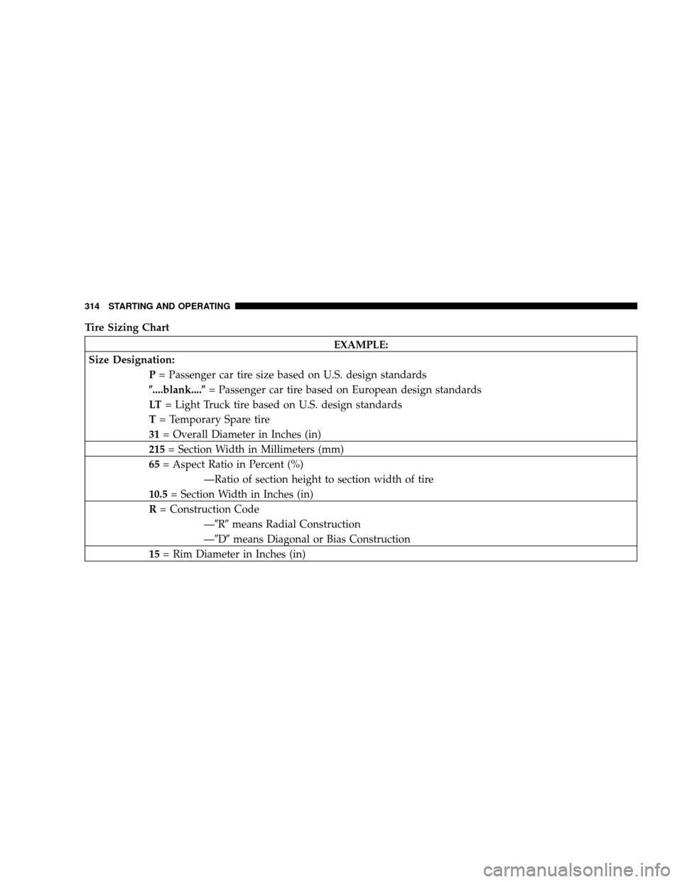
Tire Sizing Chart
EXAMPLE:
Size Designation: P= Passenger car tire size based on U.S. design standards
�....blank....� = Passenger car tire based on European design standards
LT = Light Truck tire based on U.S. design standards
T = Temporary Spare tire
31 = Overall Diameter in Inches (in)
215 = Section Width in Millimeters (mm)
65 = Aspect Ratio in Percent (%)
—Ratio of section height to section width of tire
10.5 = Section Width in Inches (in)
R = Construction Code
—�R�means Radial Construction
—�D� means Diagonal or Bias Construction
15 = Rim Diameter in Inches (in)
314 STARTING AND OPERATING
Page 347 of 466

The trailer tongue weight is the downward force exerted
on the hitch ball by the trailer. In most cases it should not
be less than 10% or more than 15% of the trailer load.")
Trailer Tongue Weight (TW)
The trailer tongue weight is the downward force exerted
on the hitch ball by the trailer. In most cases it should not
be less than 10% or more than 15% of the trailer load. You
must consider this as part of the load on your vehicle.
Frontal Area
The frontal area is the maximum height and maximum
width of the front of a trailer.
Trailer Sway Control
The trailer sway control is a telescoping link that can be
installed between the hitch receiver and the trailer
tongue. It typically provides adjustable friction associ-
ated with the telescoping motion to dampen any un-
wanted trailer swaying motions while traveling.
Weight-Carrying Hitch
A weight-carrying hitch supports the trailer tongue
weight, just as if it were luggage located at a hitch ball or
some other connecting point of the vehicle. This kind ofhitch is the most popular on the market today and is
commonly used to tow small and medium-sized trailers.
Weight-Distributing Hitch
A weight-distributing hitch system works by applying
leverage through spring (load) bars. It is typically used
for heavier loads, to distribute trailer tongue weight to
the tow vehicle’s front axle and the trailer axle(s). When
used in accordance with the manufacturers’ directions, it
provides for a more level ride, offering more consistent
steering and brake control thereby enhancing towing
safety. The addition of a friction/hydraulic sway control
also dampens sway caused by traffic and crosswinds,
and contributes positively to tow vehicle and trailer
stability. Trailer sway control and a weight-distributing
(load-equalizing) hitch are recommended for heavier
tongue weights (TW) and may be required depending on
vehicle and trailer configuration/loading to comply with
Gross Axle Weight Rating (GAWR) requirements.
346 STARTING AND OPERATING