Page 97 of 438

•After the�Ready�prompt and the following beep, say
�Emergency�and the UConnect�system will instruct
the paired cellular phone to call the emergency num-
ber. This feature is supported in the U.S., Canada, and
Mexico.
NOTE:The emergency number dialed is based on the
country where the vehicle is purchased (911 for the U.S.
and Canada and 060 for Mexico). The number dialed may
not be applicable with the available cellular service and
area.
The UConnect�system does slightly lower your chances
of successfully making a phone call as to that for the cell
phone directly.
Your phone must be turned on and paired to the
UConnect�system to allow use of this vehicle feature in
emergency situations, when the cell phone has network
coverage and stays paired to the UConnect�system.Towing Assistance
If you need towing assistance:
•Press the PHONE button to begin.
•After the�Ready�prompt and the following beep, say
�Towing Assistance.�
NOTE:The Towing Assistance number dialed is based
on the country where the vehicle is purchased (1-800-528-
2069 for the U.S., 1-877-213-4525 for Canada, 55-14-3454
for Mexico City and 1-800-712-3040 for outside Mexico
City in Mexico).
Please refer to the 24-Hour “Towing Assistance” cover-
age details in the Warranty Information Booklet and on
the 24–Hour Towing Assistance Card.
UNDERSTANDING THE FEATURES OF YOUR VEHICLE 95
3
Page 110 of 438
Voice Commands
Primary Alternate(s)
language
list names
list phones
mobile
mute
mute off
new entry
no
pager
pair a phone
phone pairing pairing
phonebook phone book
previous
record again
redialVoice Commands
Primary Alternate(s)
return to main menu return or main menu
select phone select
send
set up phone settings or phone
set up
towing assistance
transfer call
UConnect�Tutorial
try again
voice training
work
yes
108 UNDERSTANDING THE FEATURES OF YOUR VEHICLE
Page 174 of 438

INSTRUMENT CLUSTER DESCRIPTIONS
1. Fuel Gauge/Fuel Door Location
When the ignition switch is in the ON position,
the pointer will show the level of fuel remain-
ing in the fuel tank. The fuel pump symbol
points to the side of the vehicle where the fuel
door is located.
2. Voltage Warning Light
This light shows the status of the electrical charg-
ing system. The light should come on when the
ignition switch is first turned ON and remain on briefly
as a bulb check. If the Voltage Warning light remains on,
or comes on while driving, it means that the vehicle is
experiencing a problem with the charging system. Obtain
SERVICE IMMEDIATELY. See your authorized dealer.3. Electronic Throttle Control (ETC) Warning Light
This light informs you of a problem with the
Electronic Throttle Control system. If a prob-
lem is detected, the light will come on while the
engine is running. If the light remains lit with
the engine running, your vehicle will usually be drivable
and not need towing, however see your authorized
dealer for service as soon as possible.
If the light is flashing when the engine is running you
may experience power loss, an elevated/rough idle, and
increased brake pedal effort, and your vehicle may
require towing. Immediate service is required.
The light will come on when the ignition switch is first
turned ON and remain on briefly as a bulb check. This is
normal. If the light does not come on during starting,
have the system checked by an authorized dealer.
172 UNDERSTANDING YOUR INSTRUMENT PANEL
Page 183 of 438

This light is part of an Onboard Diagnostic
system called OBD II that monitors emissions,
engine, and automatic transmission control sys-
tems. The light will ill")
26. Malfunction Indicator Light (MIL)
This light is part of an Onboard Diagnostic
system called OBD II that monitors emissions,
engine, and automatic transmission control sys-
tems. The light will illuminate when the key is in the
ON/RUN position before engine start. If the light does
not come on when turning the key from OFF to ON/
RUN, have the condition checked promptly.
Certain conditions such as a loose or missing gas cap,
poor fuel quality, etc., may illuminate the light after
engine start. The vehicle should be serviced if the light
stays on through several of your typical driving cycles. In
most situations the vehicle will drive normally and will
not require towing.
If the MIL flashes when the engine is running, serious
conditions may exist that could lead to immediate loss of
power or severe catalytic converter damage. The vehicle
should be serviced as soon as possible if this occurs.27. Hill Descent Indicator Light — If Equipped
The symbol illuminates (is armed) when the
4WD Lock switch is activated and the trans-
mission range indicator is in LOW or REVERSE
position (Off-Road Mode).
28. Front Fog Light Indicator Light — If Equipped
This light shows when the front fog lights are on.
29. Electronic Stability Program (ESP) Indicator
Light/Traction Control System (TCS) Indicator Light —
If Equipped
If this indicator light flashes during accelera-
tion, apply as little throttle as possible. While
driving, ease up on the accelerator. Adapt your
speed and driving to the prevailing road con-
ditions, and do not switch off the ESP, or TCS — if
equipped.
UNDERSTANDING YOUR INSTRUMENT PANEL 181
4
Page 240 of 438
▫Loose Fuel Filler Cap Message............316
�Vehicle Loading........................317
▫Gross Vehicle Weight Rating (GVWR).......317
�TrailerTowing .........................317
▫Common Towing Definitions.............318
▫Trailer Hitch Classification...............320
▫Trailer Towing Weights (Maximum Trailer
Weight Ratings)......................321▫Trailer And Tongue Weight..............322
▫Towing Requirements..................323
▫TowingTips .........................327
�Recreational Towing
(Behind Motorhome, Etc.).................329
▫Towing This Vehicle Behind Another Vehicle
(Flat Towing With All Four Wheels On The
Ground)............................329
238 STARTING AND OPERATING
Page 251 of 438
AUTOSTICK�— IF EQUIPPED
Autostick�is a driver-interactive transmission that offers
six manual ratio changes to provide you with more
control. Autostick�allows you to maximize engine brak-
ing, eliminate undesirable upshifts and downshifts, and
improve overall vehicle performance. This system can
also provide you with more control during passing, city
driving, cold slippery conditions, mountain driving,
trailer towing, and many other situations. Automatic
ratio changes upward will only occur to protect the
Continuously Variable Automatic Transaxle (CVT)
and/or the engine from overspeed. Changes down will
only happen at minimum engine speed to prevent stall-
ing.
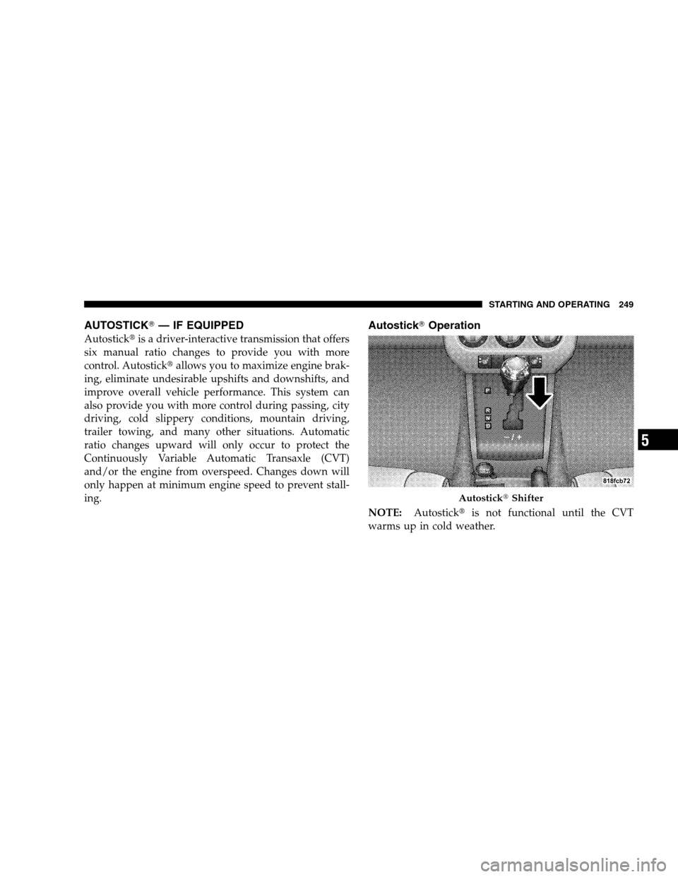
Autostick�Operation
NOTE:Autostick�is not functional until the CVT
warms up in cold weather.
Autostick�Shifter
STARTING AND OPERATING 249
5
Page 290 of 438

Loading
The vehicle maximum load on the tire must not exceed
the load carrying capacity of the tire on your vehicle. You
will not exceed the tire’s load carrying capacity if you
adhere to the loading conditions, tire size, and cold tire
inflation pressures specified on the Tire and Loading
Information placard and in the “Vehicle Loading” section
of this manual.
NOTE:Under a maximum loaded vehicle condition,
gross axle weight ratings (GAWRs) for the front and rear
axles must not be exceeded. For further information on
GAWRs, vehicle loading, and trailer towing, refer to
“Vehicle Loading” in this section.
To determine the maximum loading conditions of your
vehicle, locate the statement “The combined weight of
occupants and cargo should never exceed XXX kg or XXX
lbs.” on the Tire and Loading Information placard. Thecombined weight of occupants, cargo/luggage and
trailer tongue weight (if applicable) should never exceed
the weight referenced here.
Steps for Determining Correct Load Limit
1. Locate the statement “The combined weight of occu-
pants and cargo should never exceed XXX kg or XXX lbs”
on your vehicle’s placard.
2. Determine the combined weight of the driver and
passengers that will be riding in your vehicle.
3. Subtract the combined weight of the driver and pas-
sengers from XXX kg or XXX lbs.
4. The resulting figure equals the available amount of
cargo and luggage load capacity. For example, if “XXX”
amount equals 1,400 lbs (635 kg) and there will be five
150 lb (68 kg) passengers in your vehicle, the amount of
available cargo and luggage load capacity is 650 lbs (295
kg) (since 5 x 150 = 750, and 1400 – 750 = 650 lbs [295 kg]).
288 STARTING AND OPERATING
Page 291 of 438
5. Determine the combined weight of luggage and cargo
being loaded on the vehicle. That weight may not safely
exceed the available cargo and luggage load capacity
calculated in Step 4.
6. If your vehicle will be towing a trailer, load from your
trailer will be transferred to your vehicle. Consult this
manual to determine how this reduces the available
cargo and luggage load capacity of your vehicle.
NOTE:The following table shows examples on how to
calculate total load, cargo/luggage, and towing capaci-
ties of your vehicle with varying seating configurationsand number and size of occupants. This table is for
illustration purposes only and may not be accurate for
the seating and load carry capacity of your vehicle.
NOTE:For the following example, the combined weight
of occupants and cargo should never exceed 865 lbs (392
kg).
STARTING AND OPERATING 289
5

language
list names
list phones
mobile
mute
mute off
new entry
no
pager
pair a phone
phone pairing pairing
phonebook phone book
previous
record again
redialVoice Co")