Page 3341 of 4083
SN-16
< COMPONENT DIAGNOSIS >
SONAR SENSOR CIRCUIT INSPECTION
4. Check continuity between sonar control unit harness connectors
(A, B) and ground.
Are the inspection results normal?
YES >> Inspection End.
NO >> Repair harness or connector.
Connector TerminalContinuity
B56 (A) 9, 12, 13, 14, 15, 16 GroundNo
B57 (B) 17, 19, 20, 24, 25, 26
AWNIA1878ZZ
Revision: March 2010 2008 QX56
Page 3342 of 4083
SN
SONAR BUZZER CIRCUIT INSPECTIONSN-17
< COMPONENT DIAGNOSIS >
C
DE
F
G H
I
J
K L
M B A
O P
SONAR BUZZER CIRCUIT INSPECTION
DescriptionINFOID:0000000004832346
When the A/T selector lever is not it park or neutral, a stationary object will be detected by the sonar sensors
causing the front or rear sonar buzzer to sound a tone. As the vehicle moves closer to the object, the rate of
the tone will increase. When the object is very cl ose to the vehicle, the tone will sound continuously.
Diagnosis Procedure (With Rear Sonar System)INFOID:0000000004832347
1.CHECK SONAR BUZZER
Refer to SN-18, "
Component Inspection".
Is the inspection result normal?
YES >> GO TO 2.
NO >> Replace sonar buzzer. Refer to SN-51, "
Removal and Installation".
2.CHECK SONAR BUZZER CIRCUITS
1. Turn ignition switch OFF.
2. Disconnect sonar control unit connector and sonar buzzer connector.
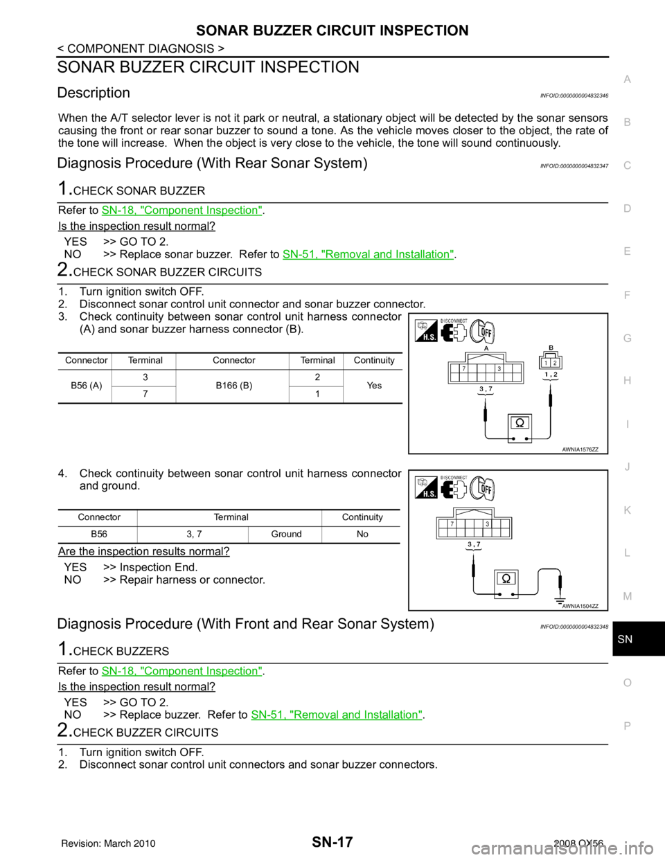
3. Check continuity between sonar control unit harness connector (A) and sonar buzzer harness connector (B).
4. Check continuity between sonar control unit harness connector and ground.
Are the inspection results normal?
YES >> Inspection End.
NO >> Repair harness or connector.
Diagnosis Procedure (With Front and Rear Sonar System)INFOID:0000000004832348
1.CHECK BUZZERS
Refer to SN-18, "
Component Inspection".
Is the inspection result normal?
YES >> GO TO 2.
NO >> Replace buzzer. Refer to SN-51, "
Removal and Installation".
2.CHECK BUZZER CIRCUITS
1. Turn ignition switch OFF.
2. Disconnect sonar control unit connec tors and sonar buzzer connectors.
Connector TerminalConnector Terminal Continuity
B56 (A) 3
B166 (B) 2
Ye s
71
AWNIA1576ZZ
Connector TerminalContinuity
B56 3, 7Ground No
AWNIA1504ZZ
Revision: March 2010 2008 QX56
Page 3346 of 4083
SN
SONAR CONTROL UNIT FOR REAR SONAR SYSTEMSN-21
< ECU DIAGNOSIS >
C
DE
F
G H
I
J
K L
M B A
O P
ECU DIAGNOSIS
SONAR CONTROL UNIT FO R REAR SONAR SYSTEM
Reference ValueINFOID:0000000001754070
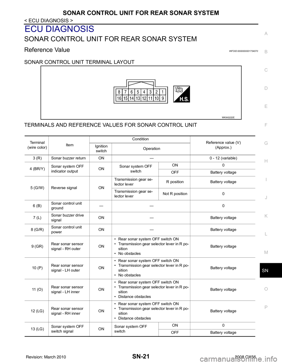
SONAR CONTROL UNIT TERMINAL LAYOUT
TERMINALS AND REFERENCE VA LUES FOR SONAR CONTROL UNIT
WKIA5222E
Te r m i n a l
(wire color) Item Condition
Reference value (V)
(Approx.)
Ignition
switch Operation
3 (R) Sonar buzzer return ON —0 - 12 (variable)
4 (BR/Y) Sonar system OFF
indicator output ON
Sonar system OFF
switch ON
0
OFF Battery voltage
5 (G/W) Reverse signal ONTransmission gear se-
lector lever
R position
Battery voltage
Transmission gear se-
lector lever Not R position
0
6 (B) Sonar control unit
ground ——
0
7 (L) Sonar buzzer drive
signal
ON
— Battery voltage
8 (G/R) Sonar control unit
power ON
— Battery voltage
9 (GR) Rear sonar sensor
signal - RH outer
ON• Rear sonar system OFF switch ON
• Transmission gear selector lever in R po-
sition
• No obstacles Battery voltage
10 (P) Rear sonar sensor
signal - LH outer
ON• Rear sonar system OFF switch ON
• Transmission gear selector lever in R po-
sition
• No obstacles Battery voltage
11 ( O ) Rear sonar sensor
signal - LH inner
ON• Rear sonar system OFF switch ON
• Transmission gear selector lever in R po-
sition
• Distance obstacles Battery voltage
12 (LG) Rear sonar sensor
signal - RH inner
ON• Rear sonar system OFF switch ON
• Transmission gear selector lever in R po-
sition
• Distance obstacles Battery voltage
13 (LG) Sonar system OFF
switch signal
ONSonar system OFF
switch ON
0
OFF Battery voltage
Revision: March 2010 2008 QX56
Page 3347 of 4083
SN-22
< ECU DIAGNOSIS >
SONAR CONTROL UNIT FOR REAR SONAR SYSTEM
15 (Y)Rear sonar sensor
ground
ON
— 0
16 (LG/B) Rear sonar sensor
power ON Ignition switch ON
Battery voltage
Te r m i n a l
(wire color) Item Condition
Reference value (V)
(Approx.)
Ignition
switch Operation
Revision: March 2010
2008 QX56
Page 3355 of 4083
SN-30
< ECU DIAGNOSIS >
SONAR CONTROL UNIT FOR REAR SONAR SYSTEM
DTC Index
INFOID:0000000001754072
Fault Code Malfunction Service Procedure
11 Rear sonar sensor LH outer 1. Check harness for open or short.
2. Replace sonar sensor. Refer to SN-49, "
Removal and In-
stallation".
12
Rear sonar sensor LH inner
13 Rear sonar sensor RH inner
14 Rear sonar sensor RH outer
21 Rear sonar buzzer 1. Refer to SN-17, "
Diagnosis Procedure (With Rear Sonar
System)".
2. Check harness for open or short.
3. Refer to SN-45, "
Symptom Table".
22 Sonar system OFF indicator 1. Refer to SN-19, "
Diagnosis Procedure (With Rear Sonar
System)".
2. Check harness for open or short.
3. Refer to symptom table.
23
Sonar system OFF switch
24 Sonar control unit Replace sonar control unit. Refer to
SN-50, "
Removal and In-
stallation".
Revision: March 2010 2008 QX56
Page 3356 of 4083
SN
SONAR CONTROL UNIT FOR FRONT AND REAR SONAR SYSTEMSN-31
< ECU DIAGNOSIS >
C
DE
F
G H
I
J
K L
M B A
O P
SONAR CONTROL UNIT FOR FR ONT AND REAR SONAR SYSTEM
Reference ValueINFOID:0000000001754073
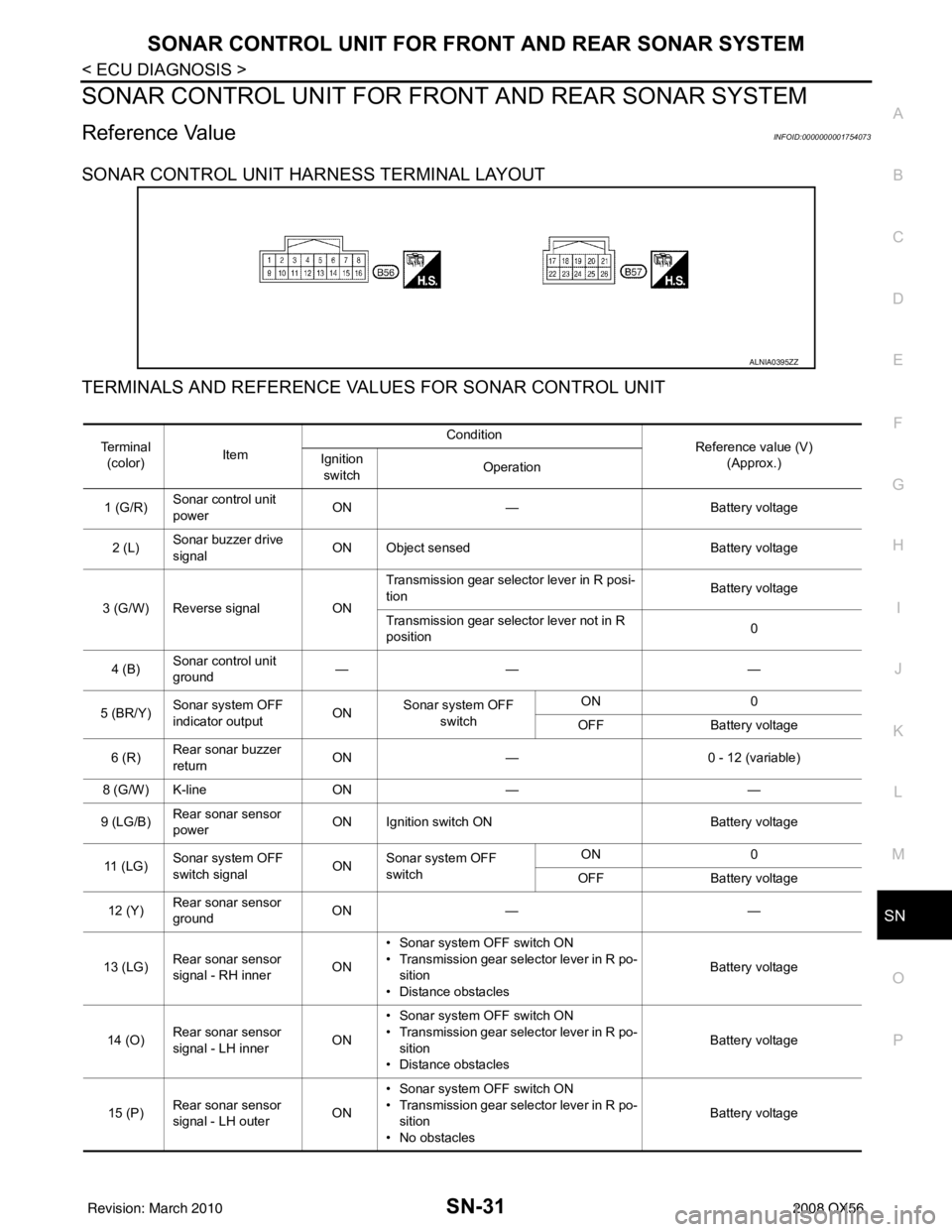
SONAR CONTROL UNIT HARNESS TERMINAL LAYOUT
TERMINALS AND REFERENCE VA LUES FOR SONAR CONTROL UNIT
ALNIA0395ZZ
Te r m i n a l
(color) Item Condition
Reference value (V)
(Approx.)
Ignition
switch Operation
1 (G/R) Sonar control unit
power ON
— Battery voltage
2 (L) Sonar buzzer drive
signal
ON Object sensed
Battery voltage
3 (G/W) Reverse signal ONTransmission gear selector lever in R posi-
tion
Battery voltage
Transmission gear selector lever not in R
position 0
4 (B) Sonar control unit
ground ——
—
5 (BR/Y) Sonar system OFF
indicator output ON
Sonar system OFF
switch ON
0
OFF Battery voltage
6 (R) Rear sonar buzzer
return
ON
— 0 - 12 (variable)
8 (G/W) K-line ON— —
9 (LG/B) Rear sonar sensor
power ON Ignition switch ON
Battery voltage
11 ( L G ) Sonar system OFF
switch signal
ONSonar system OFF
switch ON
0
OFF Battery voltage
12 (Y) Rear sonar sensor
ground ON
— —
13 (LG) Rear sonar sensor
signal - RH inner ON• Sonar system OFF switch ON
• Transmission gear selector lever in R po-
sition
• Distance obstacles Battery voltage
14 (O) Rear sonar sensor
signal - LH inner ON• Sonar system OFF switch ON
• Transmission gear selector lever in R po-
sition
• Distance obstacles Battery voltage
15 (P) Rear sonar sensor
signal - LH outer ON• Sonar system OFF switch ON
• Transmission gear selector lever in R po-
sition
• No obstacles Battery voltage
Revision: March 2010
2008 QX56
Page 3357 of 4083
SN-32
< ECU DIAGNOSIS >
SONAR CONTROL UNIT FOR FRONT AND REAR SONAR SYSTEM
16 (GR)Rear sonar sensor
signal - RH outer ON• Sonar system OFF switch ON
• Transmission gear selector lever in R po-
sition
• No obstacles Battery voltage
17 (LG/B) Front sonar sensor
power
ON Ignition switch ON
Battery voltage
18 (GR/R) Park position signal ON Vehicle in PARK 12
19 (GR) Front sonar sensor
signal - RH outer ON• Sonar system OFF switch ON
• Transmission gear selector lever in a for-
ward drive gear
• Distance obstacles Battery voltage
20 (LG) Front sonar sensor
signal - RH inner ON• Sonar system OFF switch ON
• Transmission gear selector lever in re-
verse or a forward drive gear
• No obstacles Battery voltage
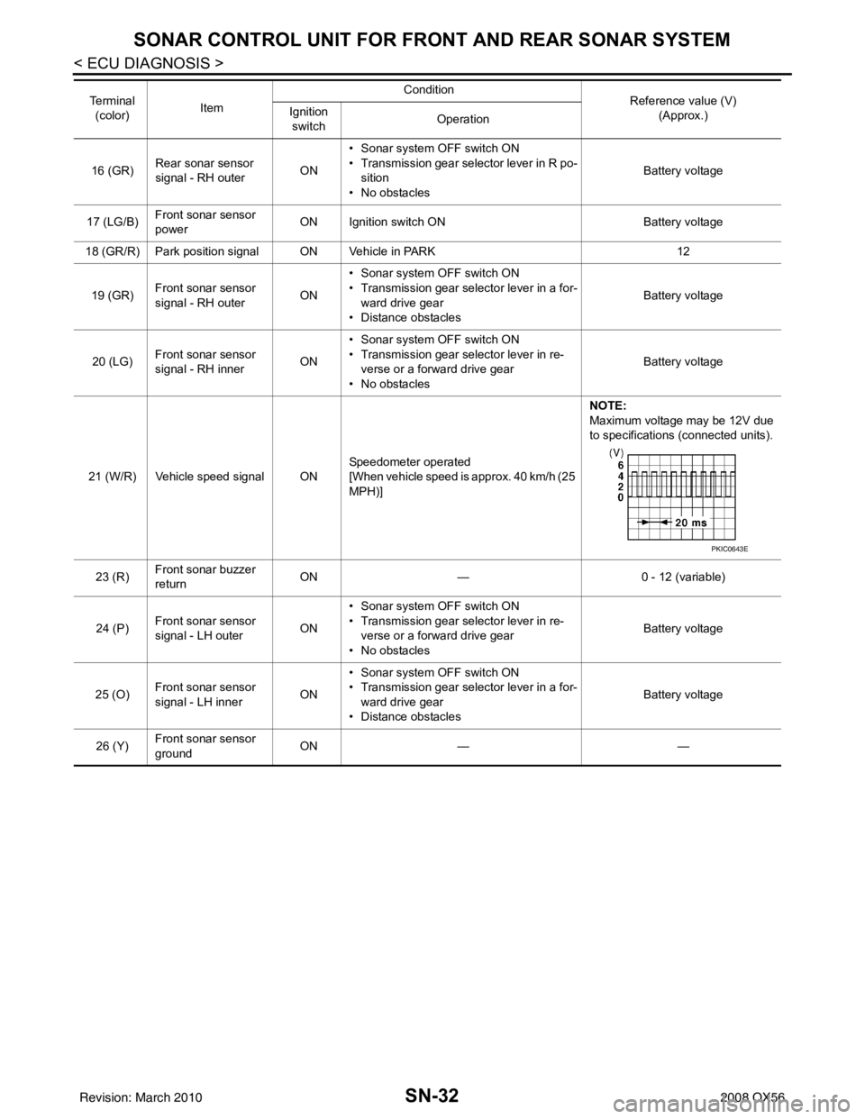
21 (W/R) Vehicle speed signal ON Speedometer operated
[When vehicle speed is approx. 40 km/h (25
MPH)]NOTE:
Maximum voltage may be 12V due
to specifications (connected units).
23 (R) Front sonar buzzer
return ON
— 0 - 12 (variable)
24 (P) Front sonar sensor
signal - LH outer
ON• Sonar system OFF switch ON
• Transmission gear selector lever in re-
verse or a forward drive gear
• No obstacles Battery voltage
25 (O) Front sonar sensor
signal - LH inner
ON• Sonar system OFF switch ON
• Transmission gear selector lever in a for-
ward drive gear
• Distance obstacles Battery voltage
26 (Y) Front sonar sensor
ground ON
— —
Te r m i n a l
(color) Item Condition
Reference value (V)
(Approx.)
Ignition
switch Operation
PKIC0643E
Revision: March 2010
2008 QX56
Page 3369 of 4083
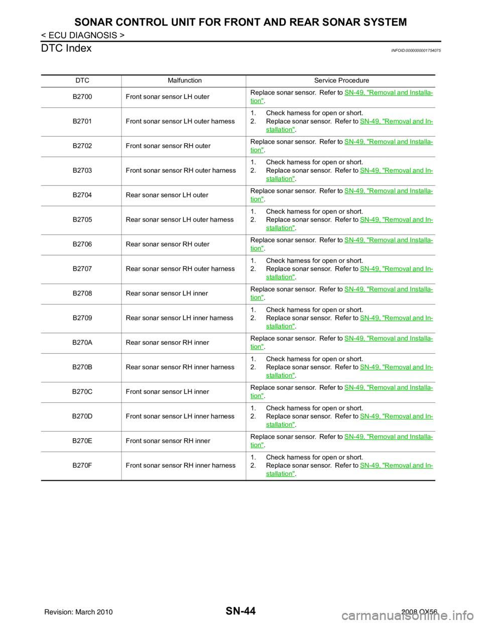
SN-44
< ECU DIAGNOSIS >
SONAR CONTROL UNIT FOR FRONT AND REAR SONAR SYSTEM
DTC Index
INFOID:0000000001754075
DTC Malfunction Service Procedure
B2700 Front sonar sensor LH outer Replace sonar sensor. Refer to
SN-49, "
Removal and Installa-
tion".
B2701 Front sonar sensor LH outer harness 1. Check harness for open or short.
2. Replace sonar sensor. Refer to
SN-49, "
Removal and In-
stallation".
B2702 Front sonar sensor RH outer Replace sonar sensor. Refer to
SN-49, "
Removal and Installa-
tion".
B2703 Front sonar sensor RH outer harness 1. Check harness for open or short.
2. Replace sonar sensor. Refer to
SN-49, "
Removal and In-
stallation".
B2704 Rear sonar sensor LH outer Replace sonar sensor. Refer to
SN-49, "
Removal and Installa-
tion".
B2705 Rear sonar sensor LH outer harness 1. Check harness for open or short.
2. Replace sonar sensor. Refer to
SN-49, "
Removal and In-
stallation".
B2706 Rear sonar sensor RH outer Replace sonar sensor. Refer to
SN-49, "
Removal and Installa-
tion".
B2707 Rear sonar sensor RH outer harness 1. Check harness for open or short.
2. Replace sonar sensor. Refer to
SN-49, "
Removal and In-
stallation".
B2708 Rear sonar sensor LH inner Replace sonar sensor. Refer to
SN-49, "
Removal and Installa-
tion".
B2709 Rear sonar sensor LH inner harness 1. Check harness for open or short.
2. Replace sonar sensor. Refer to
SN-49, "
Removal and In-
stallation".
B270A Rear sonar sensor RH inner Replace sonar sensor. Refer to
SN-49, "
Removal and Installa-
tion".
B270B Rear sonar sensor RH inner harness 1. Check harness for open or short.
2. Replace sonar sensor. Refer to
SN-49, "
Removal and In-
stallation".
B270C Front sonar sensor LH inner Replace sonar sensor. Refer to
SN-49, "
Removal and Installa-
tion".
B270D Front sonar sensor LH inner harness 1. Check harness for open or short.
2. Replace sonar sensor. Refer to
SN-49, "
Removal and In-
stallation".
B270E Front sonar sensor RH inner Replace sonar sensor. Refer to
SN-49, "
Removal and Installa-
tion".
B270F Front sonar sensor RH inner harness 1. Check harness for open or short.
2. Replace sonar sensor. Refer to
SN-49, "
Removal and In-
stallation".
Revision: March 2010 2008 QX56