Page 3801 of 4083
TM-254
< DISASSEMBLY AND ASSEMBLY >
REPAIR FOR COMPONENT PARTS
2. Install snap ring in front sun gear using suitable tool.
3. Check operation of 3rd one-way clutch.
a. Hold oil pump assembly and turn front sun gear.
b. Check 3rd one-way clutch for correct locking and unlockingdirections.
CAUTION:
If not as shown, check installa tion direction of 3rd one-way
clutch.
Front Carrier, Input Clutc h, Rear Internal GearINFOID:0000000004917898
COMPONENTS
SCIA3110E
SCIA3131E
Revision: March 2010 2008 QX56
Page 3811 of 4083
TM-264
< DISASSEMBLY AND ASSEMBLY >
REPAIR FOR COMPONENT PARTS
6. Install high and low reverse clutch hub to mid sun gear assem-bly.
7. Install snap ring to mid sun gear assembly using suitable tool. CAUTION:
Do not expand snap ring excessively.
8. Check operation of 1st one-way clutch.
a. Hold mid sun gear and turn rear sun gear.
b. Check 1st one-way clutch for correct locking and unlocking directions.
CAUTION:
If not as shown, check installa tion direction of 1st one-way
clutch.
9. Install needle bearing and bearing races to high and low reverse clutch hub.
CAUTION:
• Apply petroleum jelly to n eedle bearing and bearing
races.
• Take care with order of bearing races.
High and Low Reverse ClutchINFOID:0000000004917900
COMPONENTS
SCIA2856E
SCIA2855E
SCIA3132E
SCIA5238E
Revision: March 2010 2008 QX56
Page 3828 of 4083
ASSEMBLYTM-281
< DISASSEMBLY AND ASSEMBLY >
CEF
G H
I
J
K L
M A
B
TM
N
O P
48. Install band servo anchor end pin and lock nut in transmission case.
CAUTION:
Do not reuse band servo anchor end pin.
49. Install brake band in transmission case. CAUTION:
Install it so that the identificat ion to avoid incorrect installa-
tion faces the servo side.
50. Install front sun gear to front carrier assembly. CAUTION:
Apply ATF to front sun gear bearing and 3rd one-way clutch
end bearing.
51. Install needle bearing to front sun gear. CAUTION:
Apply petroleum jelly to needle bearing.
52. Adjust brake band tilting using a clip so that brake band contacts front sun gear drum evenly.
SCIA6512E
SCIA5498E
SCIA5014E
SCIA2808E
SCIA5033E
Revision: March 2010 2008 QX56
Page 3829 of 4083
TM-282
< DISASSEMBLY AND ASSEMBLY >
ASSEMBLY
53. Adjust brake band.
a. Loosen lock nut.
b. Tighten band servo anchor end pin to specified torque.
c. Back off band servo anchor end pin three turns.
d. Holding band servo anchor end pin, tighten lock nut to specifiedtorque.
AdjustmentINFOID:0000000004917903
TOTAL END PLAY
• Measure clearance between front sun gear and bearing race for oilpump cover.
• Select proper thickness of bearing race so that end play is within specifications.
1. Measure dimensions “K” and “L” and then calculate dimension “J”.
a. Measure dimension “K”. Anchor end pin : 5.0 N·m (0.51 kg-m, 44 in-lb)
Lock nut : 46 N·m (4.7 kg-m, 34 ft-lb)
SCIA5498E
SCIA2810E
SCIA5350E
SCIA5351E
Revision: March 2010
2008 QX56
Page 3838 of 4083

SERVICE DATA AND SPECIFICATIONS (SDS)TM-291
< SERVICE DATA AND SPECIFICATIONS (SDS)
CEF
G H
I
J
K L
M A
B
TM
N
O P
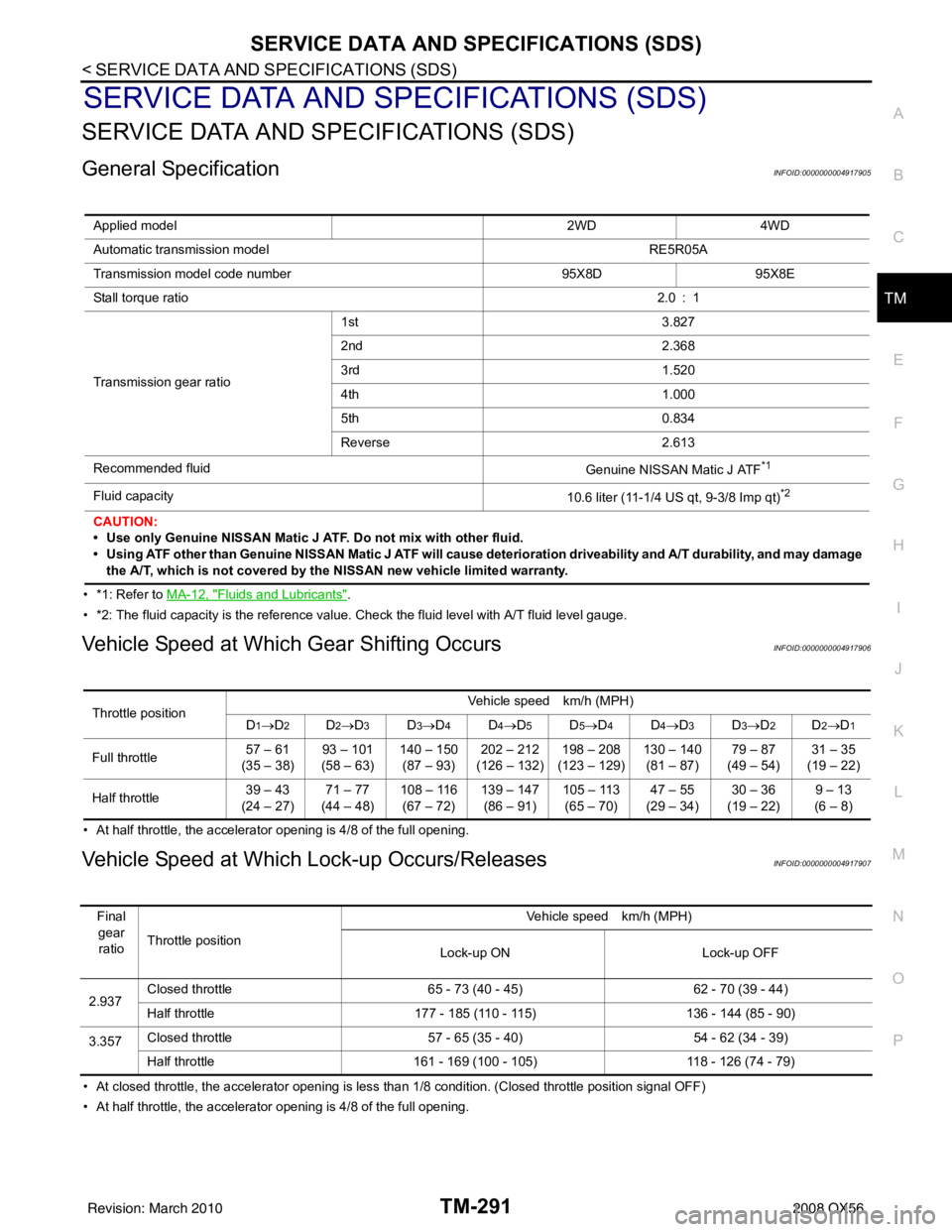
SERVICE DATA AND SPECIFICATIONS (SDS)
SERVICE DATA AND SPECIFICATIONS (SDS)
General SpecificationINFOID:0000000004917905
• *1: Refer to MA-12, "Fluids and Lubricants".
• *2: The fluid capacity is the reference value. Check the fluid level with A/T fluid level gauge.
Vehicle Speed at Which Gear Shifting OccursINFOID:0000000004917906
• At half throttle, the accelerator opening is 4/8 of the full opening.
Vehicle Speed at Which Lock-up Occurs/ReleasesINFOID:0000000004917907
• At closed throttle, the accelerator opening is less than 1/8 condition. (Closed throttle position signal OFF)
• At half throttle, the accelerator opening is 4/8 of the full opening. Applied model
2WD4WD
Automatic transmission model RE5R05A
Transmission model code number 95X8D95X8E
Stall torque ratio 2.0 : 1
Transmission gear ratio 1st
3.827
2nd 2.368
3rd 1.520
4th 1.000
5th 0.834
Reverse 2.613
Recommended fluid Genuine NISSAN Matic J ATF
*1
Fluid capacity10.6 liter (11-1/4 US qt, 9-3/8 Imp qt)*2
CAUTION:
• Use only Genuine NISSAN Matic J ATF. Do not mix with other fluid.
• Using ATF other than Genuine NISSAN Matic J ATF will cause deterioration driveability and A/ T durability, and may damage
the A/T, which is not covered by the NISSAN new vehicle limited warranty.
Throttle position Vehicle speed km/h (MPH)
D1→D2D2→ D3D3→D4D4→D5D5→D4D4→D3D3→D2D2→D1
Full throttle 57 – 61
(35 – 38) 93 – 101
(58 – 63) 140 – 150
(87 – 93) 202 – 212
(126 – 132) 198 – 208
(123 – 129) 130 – 140
(81 – 87) 79 – 87
(49 – 54) 31 – 35
(19 – 22)
Half throttle 39 – 43
(24 – 27) 71 – 77
(44 – 48) 108 – 116
(67 – 72) 139 – 147
(86 – 91) 105 – 113
(65 – 70) 47 – 55
(29 – 34) 30 – 36
(19 – 22) 9 – 13
(6 – 8)
Final gear ratio Throttle position Vehicle speed km/h (MPH)
Lock-up ON Lock-up OFF
2.937 Closed throttle
65 - 73 (40 - 45) 62 - 70 (39 - 44)
Half throttle 177 - 185 (110 - 115) 136 - 144 (85 - 90)
3.357 Closed throttle
57 - 65 (35 - 40) 54 - 62 (34 - 39)
Half throttle 161 - 169 (100 - 105) 118 - 126 (74 - 79)
Revision: March 2010 2008 QX56
Page 3842 of 4083

VTL-2
< PRECAUTION >
PRECAUTIONS
PRECAUTION
PRECAUTIONS
Precaution for Supplemental Restraint System (SRS) "AIR BAG" and "SEAT BELT
PRE-TENSIONER"
INFOID:0000000004884177
The Supplemental Restraint System such as “A IR BAG” and “SEAT BELT PRE-TENSIONER”, used along
with a front seat belt, helps to reduce the risk or severity of injury to the driver and front passenger for certain
types of collision. This system includes seat belt switch inputs and dual stage front air bag modules. The SRS
system uses the seat belt switches to determine the front air bag deployment, and may only deploy one front
air bag, depending on the severity of a collision and w hether the front occupants are belted or unbelted.
Information necessary to service the system safely is included in the SR and SB section of this Service Man-
ual.
WARNING:
• To avoid rendering the SRS inopera tive, which could increase the risk of personal injury or death in
the event of a collision which would result in air bag inflation, all maintenance must be performed by
an authorized NISSAN/INFINITI dealer.
• Improper maintenance, including in correct removal and installation of the SRS, can lead to personal
injury caused by unintent ional activation of the system. For re moval of Spiral Cable and Air Bag
Module, see the SR section.
• Do not use electrical test equipmen t on any circuit related to the SRS unless instructed to in this
Service Manual. SRS wiring harn esses can be identified by yellow and/or orange harnesses or har-
ness connectors.
PRECAUTIONS WHEN USING POWER TOOLS (AIR OR ELECTRIC) AND HAMMERS
WARNING:
• When working near the Airbag Diagnosis Sensor Unit or other Airbag System sensors with the Igni-
tion ON or engine running, DO NOT use air or electri c power tools or strike near the sensor(s) with a
hammer. Heavy vibration could activate the sensor( s) and deploy the air bag(s), possibly causing
serious injury.
• When using air or electric power tools or hammers , always switch the Ignition OFF, disconnect the
battery, and wait at least 3 minu tes before performing any service.
Precaution Necessary for Steering W heel Rotation After Battery Disconnect
INFOID:0000000004884178
NOTE:
• This Procedure is applied only to models with Intelligent Key system and NATS (NISSAN ANTI-THEFT SYS-
TEM).
• Remove and install all control units after disconnecting both battery cables with the ignition knob in the
″LOCK ″ position.
• Always use CONSULT-III to perform self-diagnosis as a part of each function inspection after finishing work.
If DTC is detected, perform trouble diagnosis according to self-diagnostic results.
For models equipped with the Intelligent Key system and NATS, an electrically controlled steering lock mech-
anism is adopted on the key cylinder.
For this reason, if the battery is disconnected or if the battery is discharged, the steering wheel will lock and
steering wheel rotation will become impossible.
If steering wheel rotation is required when battery pow er is interrupted, follow the procedure below before
starting the repair operation.
OPERATION PROCEDURE
1. Connect both battery cables. NOTE:
Supply power using jumper cables if battery is discharged.
2. Use the Intelligent Key or mechanical key to turn the ignition switch to the ″ACC ″ position. At this time, the
steering lock will be released.
3. Disconnect both battery cables. The steering lock will remain released and the steering wheel can be rotated.
4. Perform the necessary repair operation.
Revision: March 2010 2008 QX56
Page 3843 of 4083

PRECAUTIONSVTL-3
< PRECAUTION >
C
DE
F
G H
J
K L
M A
B
VTL
N
O P
5. When the repair work is completed, return the ignition switch to the ″LOCK ″ position before connecting
the battery cables. (At this time, the steering lock mechanism will engage.)
6. Perform a self-diagnosis check of al l control units using CONSULT-III.
Precaution for Working with HFC-134a (R-134a)INFOID:0000000001516598
WARNING:
• CFC-12 (R-12) refrigerant and HFC-134a (R-134a) refr igerant are not compatible. If the refrigerants
are mixed compressor failure is likely to occur. Refer to HA-4, "
Contaminated Refrigerant". To deter-
mine the purity of HFC-134a (R-134a) in the vehicle and recovery tank, use recovery/recycling equip-
ment and refrigerant identifier.
• Use only specified oil for the HFC-134a (R-134a) A/C system and HFC-134a (R-134a) components. If
oil other than that specified is used, compressor fa ilure is likely to occur.
• The specified HFC-134a (R-134a) oil rapidly absorb s moisture from the atmosphere. The following
handling precautions must be observed:
- When removing refrigerant components from a vehicle, immediately cap (seal) the component to
minimize the entry of mois ture from the atmosphere.
- When installing refrigerant components to a vehicle, do not remove the caps (unseal) until just
before connecting the co mponents. Connect all refrigerant lo op components as quickly as possible
to minimize the entry of moisture into system.
- Only use the specified oil from a sealed container. Immediately r eseal containers of oil. Without
proper sealing, oil will become moisture saturat ed and should not be used.
- Avoid breathing A/C refrigerant and oil vapor or mist. Exposure may irritate eyes, nose and throat.
Remove HFC-134a (R-134a) from the A/C system usi ng certified service equipment meeting require-
ments of SAE J2210 [HFC-134a (R-134a) recycling eq uipment], or J2209 [HFC-134a (R-134a) recovery
equipment]. If accidental system discharge occurs , ventilate work area before resuming service.
Additional health and safety information may be ob tained from refrigerant and oil manufacturers.
- Do not allow A/C oil to come in contact with styrofoam parts. Damage may result.
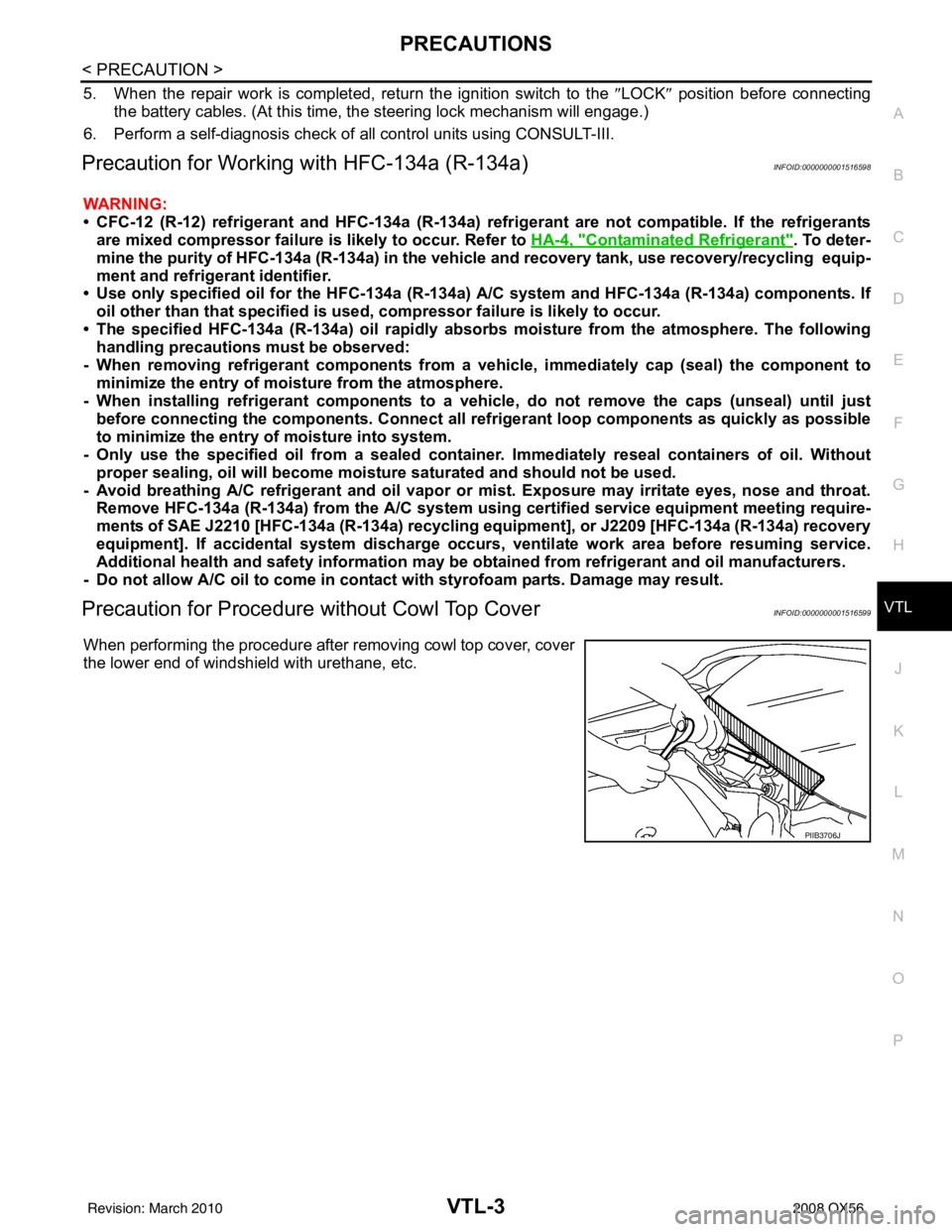
Precaution for Procedur e without Cowl Top CoverINFOID:0000000001516599
When performing the procedure after removing cowl top cover, cover
the lower end of windshield with urethane, etc.
PIIB3706J
Revision: March 2010 2008 QX56
Page 3850 of 4083
VTL-10
< ON-VEHICLE REPAIR >
OPTICAL SENSOR
OPTICAL SENSOR
Removal and InstallationINFOID:0000000001516605
REMOVAL
1. Remove the defroster grille from the instrument panel. Refer to VTL-33, "Removal and Installation".
2. Disconnect the optical sensor connector (2).
3. Twist the optical sensor (1) counter clockwise to remove it from the defroster grille.
INSTALLATION
Installation is in the reverse order of removal.
ALIIA0061ZZ
Revision: March 2010 2008 QX56