Page 3613 of 4083

TM-66
< COMPONENT DIAGNOSIS >
P0744 TORQUE CONVERTER
Diagnosis Procedure
INFOID:0000000001604086
1.CHECK INPUT SIGNAL
With CONSULT-III
1. Turn ignition switch “ON”.
2. Select “MAIN SIGNALS” in “DATA MONITO R” mode for “TRANSMISSION” with CONSULT-III.
3. Start the engine.
4. Read out the value of “TCC SOLENOID” while driving.
OK or NG
OK >> GO TO 4.
NG >> GO TO 2.
2.CHECK TCM POWER SUPPLY AND GROUND CIRCUIT
Check TCM power supply and ground circuit. Refer to TM-92, "
Diagnosis Procedure".
OK or NG
OK >> GO TO 3.
NG >> Repair or replace damaged parts.
3.DETECT MALFUNCTIONING ITEM
Check the following items:
• The A/T assembly harness connector pin terminals for damage or loose connection with harness connector.
OK or NG
OK >> Replace the control valve with TCM. Refer to TM-201, "Control Valve with TCM and A/T Fluid
Temperature Sensor 2".
NG >> Repair or replace damaged parts.
4.CHECK DTC
Perform “DTC Confirmation Procedure”.
• Refer to TM-65, "
DTC Confirmation Procedure".
OK or NG
OK >> INSPECTION END
NG >> GO TO 2.
Item name Condition Display value (Approx.)
TCC SOLENOID When performing slip lock-up
0.2 - 0.4 A
When performing lock-up 0.4 - 0.6 A
Revision: March 2010 2008 QX56
Page 3623 of 4083

TM-76
< COMPONENT DIAGNOSIS >
P1730 INTERLOCK
P1730 INTERLOCK
DescriptionINFOID:0000000001604112
• Fail-safe function to detect interlock conditions.
On Board Diagnosis LogicINFOID:0000000001604113
• This is an OBD-II self-diagnostic item.
• Diagnostic trouble code “P1730” with CONSULT-III is detected when TCM does not receive the proper volt-
age signal from the sensor and switch.
• TCM monitors and compares gear position and conditions of each ATF pressure switch when gear is steady.
Possible CauseINFOID:0000000001604114
• Harness or connectors (The solenoid and switch circuit is open or shorted.)
• Low coast brake solenoid valve
• ATF pressure switch 2
DTC Confirmation ProcedureINFOID:0000000001604115
NOTE:
If “DTC Confirmation Procedure” has been previously performed, always turn ignition switch “OFF”
and wait at least 10 seconds before performing the next test.
After the repair, perform the following proc edure to confirm the malfunction is eliminated.
WITH CONSULT-III
1. Turn ignition switch “ON”. (Do not start engine.)
2. Select “DATA MONITOR” mode for “TRANSMISSION” with CONSULT-III.
3. Start engine.
4. Drive vehicle and maintain the following conditions for at least 2 consecutive seconds. Selector lever: “D” position
5. If DTC is detected, go to TM-5, "
Work Flow".
WITH GST
Follow the procedure “With CONSULT-III”.
Judgement of InterlockINFOID:0000000001604116
• When Interlock is judged to be malfunctioning, the vehi cle should be fixed in 2GR, and should be set in a
condition in which it can travel.
NOTE:
When the vehicle is driven fixed in 2GR, a input speed sensor malfunction is displayed, but this is not a input
speed sensor malfunction.
• When interlock is detected at the 3GR or more, it is locked at the 2GR.
Diagnosis ProcedureINFOID:0000000001604117
1.SELF-DIAGNOSIS
With CONSULT-III
1. Drive vehicle.
2. Stop vehicle and turn ignition switch “OFF”.
3. Turn ignition switch “ON”.
4. Select “SELF-DIAG RESULTS” mode fo r “TRANSMISSION” with CONSULT-III.
OK or NG
OK >> GO TO 2.
NG >> Check low coast brake solenoid valve circuit and function. Refer to TM-88, "
Diagnosis Proce-
dure", TM-90, "Diagnosis Procedure".
2.CHECK DTC
Perform “DTC Confirmation Procedure”.
Revision: March 2010 2008 QX56
Page 3624 of 4083
P1730 INTERLOCKTM-77
< COMPONENT DIAGNOSIS >
CEF
G H
I
J
K L
M A
B
TM
N
O P
• Refer to TM-76, "DTC Confirmation Procedure".
OK or NG
OK >> INSPECTION END
NG >> GO TO 3.
3.CHECK TCM POWER SUPPLY AND GROUND CIRCUIT
Check TCM power supply and ground circuit. Refer to TM-92, "
Diagnosis Procedure".
OK or NG
OK >> GO TO 4.
NG >> Repair or replace damaged parts.
4.DETECT MALFUNCTIONING ITEM
Check the following items:
• The A/T assembly harness connector pin terminals for damage or loose connection with harness connector.
OK or NG
OK >> Replace the control valve with TCM. Refer to TM-201, "Control Valve with TCM and A/T Fluid
Temperature Sensor 2".
NG >> Repair or replace damaged parts.
Revision: March 2010 2008 QX56
Page 3639 of 4083

TM-92
< COMPONENT DIAGNOSIS >
MAIN POWER SUPPLY AND GROUND CIRCUIT
MAIN POWER SUPPLY AND GROUND CIRCUIT
Diagnosis ProcedureINFOID:0000000001604160
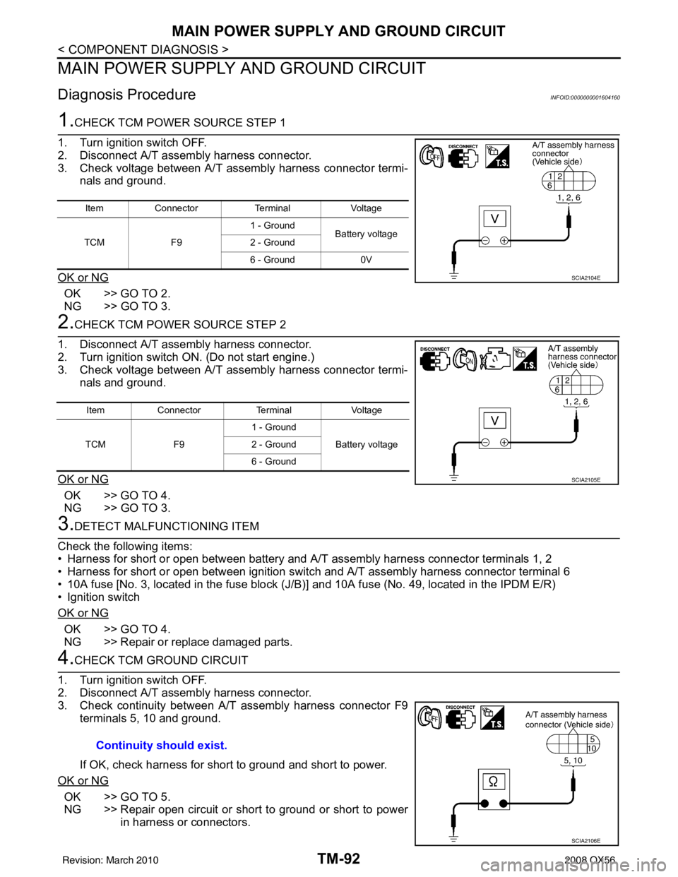
1.CHECK TCM POWER SOURCE STEP 1
1. Turn ignition switch OFF.
2. Disconnect A/T assembly harness connector.
3. Check voltage between A/T assembly harness connector termi- nals and ground.
OK or NG
OK >> GO TO 2.
NG >> GO TO 3.
2.CHECK TCM POWER SOURCE STEP 2
1. Disconnect A/T assembly harness connector.
2. Turn ignition switch ON. (Do not start engine.)
3. Check voltage between A/T assembly harness connector termi- nals and ground.
OK or NG
OK >> GO TO 4.
NG >> GO TO 3.
3.DETECT MALFUNCTIONING ITEM
Check the following items:
• Harness for short or open between battery and A/T assembly harness connector terminals 1, 2
• Harness for short or open between ignition switch and A/T assembly harness connector terminal 6
• 10A fuse [No. 3, located in the fuse block (J/B )] and 10A fuse (No. 49, located in the IPDM E/R)
• Ignition switch
OK or NG
OK >> GO TO 4.
NG >> Repair or replace damaged parts.
4.CHECK TCM GROUND CIRCUIT
1. Turn ignition switch OFF.
2. Disconnect A/T assembly harness connector.
3. Check continuity between A/T assembly harness connector F9 terminals 5, 10 and ground.
If OK, check harness for short to ground and short to power.
OK or NG
OK >> GO TO 5.
NG >> Repair open circuit or short to ground or short to power in harness or connectors.
Item Connector TerminalVoltage
TCM F91 - Ground
Battery voltage
2 - Ground
6 - Ground 0V
SCIA2104E
ItemConnector TerminalVoltage
TCM F91 - Ground
Battery voltage
2 - Ground
6 - Ground
SCIA2105E
Continuity should exist.
SCIA2106E
Revision: March 2010 2008 QX56
Page 3644 of 4083
A/T SHIFT LOCK SYSTEMTM-97
< COMPONENT DIAGNOSIS >
CEF
G H
I
J
K L
M A
B
TM
N
O P
A/T SHIFT LOCK SYSTEM
Wiring Diagram - A/ T Shift Lock SystemINFOID:0000000001696153
ABDWA0334GB
Revision: March 2010 2008 QX56
Page 3645 of 4083
TM-98
< COMPONENT DIAGNOSIS >
A/T SHIFT LOCK SYSTEM
AADIA0077GB
Revision: March 20102008 QX56
Page 3646 of 4083
A/T SHIFT LOCK SYSTEMTM-99
< COMPONENT DIAGNOSIS >
CEF
G H
I
J
K L
M A
B
TM
N
O P
ABDIA0628GB
Revision: March 2010 2008 QX56
Page 3647 of 4083

TM-100
< COMPONENT DIAGNOSIS >
A/T SHIFT LOCK SYSTEM
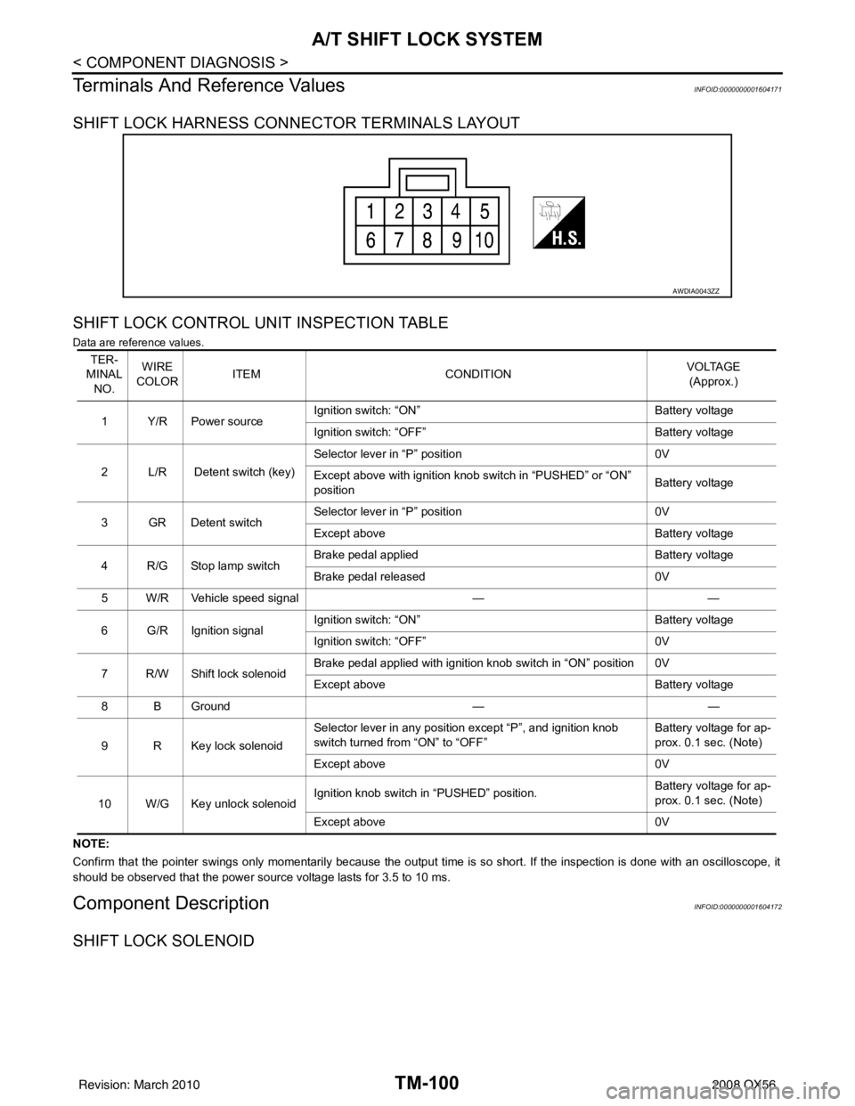
Terminals And Reference Values
INFOID:0000000001604171
SHIFT LOCK HARNESS CONNECTOR TERMINALS LAYOUT
SHIFT LOCK CONTROL UNIT INSPECTION TABLE
Data are reference values.
NOTE:
Confirm that the pointer swings only momentarily because the output time is so short. If the inspection is done with an oscillo scope, it
should be observed that the power source voltage lasts for 3.5 to 10 ms.
Component DescriptionINFOID:0000000001604172
SHIFT LOCK SOLENOID
AWDIA0043ZZ
TER-
MINAL NO. WIRE
COLOR ITEM
CONDITION VOLTAGE
(Approx.)
1Y/RPower source Ignition switch: “ON”
Battery voltage
Ignition switch: “OFF” Battery voltage
2 L/R Detent switch (key) Selector lever in “P” position
0V
Except above with ignition knob switch in “PUSHED” or “ON”
position Battery voltage
3GRDetent switch Selector lever in “P” position
0V
Except above Battery voltage
4 R/G Stop lamp switch Brake pedal applied
Battery voltage
Brake pedal released 0V
5 W/R Vehicle speed signal ——
6 G/R Ignition signal Ignition switch: “ON”
Battery voltage
Ignition switch: “OFF” 0V
7 R/W Shift lock solenoid Brake pedal applied with ignition knob switch in “ON” position 0V
Except above
Battery voltage
8 B Ground ——
9 R Key lock solenoid Selector lever in any position except “P”, and ignition knob
switch turned from “ON” to “OFF”
Battery voltage for ap-
prox. 0.1 sec. (Note)
Except above 0V
10 W/G Key unlock solenoid Ignition knob switch in “PUSHED” position.
Battery voltage for ap-
prox. 0.1 sec. (Note)
Except above 0V
Revision: March 2010 2008 QX56