2008 INFINITI QX56 check engine light
[x] Cancel search: check engine lightPage 1786 of 4083
![INFINITI QX56 2008 Factory Service Manual PRECAUTIONSEC-487
< PRECAUTION > [VK56DE]
C
D
E
F
G H
I
J
K L
M A
EC
NP
O
5. When the repair work is completed, return the ignition switch to the
″LOCK ″ position before connecting
the battery ca INFINITI QX56 2008 Factory Service Manual PRECAUTIONSEC-487
< PRECAUTION > [VK56DE]
C
D
E
F
G H
I
J
K L
M A
EC
NP
O
5. When the repair work is completed, return the ignition switch to the
″LOCK ″ position before connecting
the battery ca](/manual-img/42/57030/w960_57030-1785.png)
PRECAUTIONSEC-487
< PRECAUTION > [VK56DE]
C
D
E
F
G H
I
J
K L
M A
EC
NP
O
5. When the repair work is completed, return the ignition switch to the
″LOCK ″ position before connecting
the battery cables. (At this time, the steering lock mechanism will engage.)
6. Perform a self-diagnosis check of al l control units using CONSULT-III.
On Board Diagnosis (OBD) System of Engine and A/TINFOID:0000000001351222
The ECM has an on board diagnostic system . It will light up the malfunction indicator lamp (MIL) to warn the
driver of a malfunction causing emission deterioration.
CAUTION:
• Be sure to turn the ignition switch OFF and di sconnect the negative battery cable before any repair
or inspection work. The open/short circuit of re lated switches, sensors, solenoid valves, etc. will
cause the MIL to light up.
• Be sure to connect and lock the connectors secure ly after work. A loose (unlocked) connector will
cause the MIL to light up due to the open circuit. (Be sure the connector is free from water, grease,
dirt, bent terminals, etc.)
• Certain systems and components, especially those related to OBD, may use a new style slide-lock-
ing type harness connector. For description and how to disconnect, refer to PG-65
.
• Be sure to route and secure the harnesses properly after work. The interference of the harness with
a bracket, etc. may cause the MIL to li ght up due to the short circuit.
• Be sure to connect rubber tubes properly afte r work. A misconnected or disconnected rubber tube
may cause the MIL to light up due to the malfuncti on of the EVAP system or fuel injection system,
etc.
• Be sure to erase the unnecessary malfunction information (repairs completed) from the ECM and TCM (Transmission control module) before returning the vehicle to the customer.
PrecautionINFOID:0000000006211821
•Always use a 12 volt battery as power source.
• Do not attempt to disconnect battery cables while engine is
running.
• Before connecting or disc onnecting the ECM harness con-
nector, turn ignition switch OFF and disconnect negative bat-
tery cable. Failure to do so may damage the ECM because
battery voltage is applied to ECM even if ignition switch is
turned OFF.
• Before removing parts, turn ig nition switch OFF and then dis-
connect negative battery cable.
• Do not disassemble ECM.
• If a battery cable is disconnected, the memory will return to
the ECM value.
The ECM will now start to sel f-control at its initial value.
Engine operation can vary slight ly when the terminal is dis-
connected. However, this is not an indication of a malfunc-
tion. Do not replace parts because of a slight variation.
• If the battery is disconnected, the following emission-related
diagnostic information will be lost within 24 hours.
- Diagnostic trouble codes
- 1st trip diagnostic trouble codes
- Freeze frame data
- 1st trip freeze frame data
- System readiness test (SRT) codes
- Test values
-
Presumed ethanol mixture ratio
SEF289H
PBIB1164E
Revision: March 2010 2008 QX56
Page 1787 of 4083
![INFINITI QX56 2008 Factory Service Manual EC-488
< PRECAUTION >[VK56DE]
PRECAUTIONS
•
When connecting ECM harness co nnector, fasten it securely
with a lever as far as it will go as shown in the figure.
• When connecting or disconnect in INFINITI QX56 2008 Factory Service Manual EC-488
< PRECAUTION >[VK56DE]
PRECAUTIONS
•
When connecting ECM harness co nnector, fasten it securely
with a lever as far as it will go as shown in the figure.
• When connecting or disconnect in](/manual-img/42/57030/w960_57030-1786.png)
EC-488
< PRECAUTION >[VK56DE]
PRECAUTIONS
•
When connecting ECM harness co nnector, fasten it securely
with a lever as far as it will go as shown in the figure.
• When connecting or disconnect ing pin connectors into or
from ECM, take care not to damage pin terminals (bend or
break).
Make sure that there are not any bends or breaks on ECM pin
terminal, when connecting pin connectors.
• Securely connect ECM harness connectors.
A poor connection can cause an extremely high (surge) volt-
age to develop in coil and co ndenser, thus resulting in dam-
age to ICs.
• Keep engine control system harness at least 10 cm (4 in) away
from adjacent harness, to preven t engine control system mal-
functions due to receiving external noise, degraded operation
of ICs, etc.
• Keep engine control system parts and harness dry.
• Before replacing ECM, perform ECM Terminals and Reference
Value inspection and make sure ECM functions properly.
Refer to EC-429, "
ECM Terminal and Reference Value".
• Handle mass air flow sensor carefully to avoid damage.
• Do not disassemble m ass air flow sensor.
• Do not clean mass air flow sensor with any type of detergent.
• Do not disassemble electric throttle control actuator.
• Even a slight leak in the ai r intake system can cause serious
incidents.
• Do not shock or jar the camshaft position sensor (PHASE),
crankshaft position sensor (POS).
• After performing each TROUBLE DIAGNOSIS, perform DTC
Confirmation Procedure or Overall Function Check.
The DTC should not be displ ayed in the DTC Confirmation
Procedure if the repair is co mpleted. The Overall Function
Check should be a good result if the repair is completed.
BBIA0387E
PBIB0090E
MEF040D
SEF217U
Revision: March 2010 2008 QX56
Page 1793 of 4083
![INFINITI QX56 2008 Factory Service Manual EC-494
< ON-VEHICLE MAINTENANCE >[VK56DE]
FUEL PRESSURE
ON-VEHICLE MAINTENANCE
FUEL PRESSURE
Fuel Pressure CheckINFOID:0000000001351336
FUEL PRESSURE RELEASE
With CONSULT-IIl
1. Turn ignition switch INFINITI QX56 2008 Factory Service Manual EC-494
< ON-VEHICLE MAINTENANCE >[VK56DE]
FUEL PRESSURE
ON-VEHICLE MAINTENANCE
FUEL PRESSURE
Fuel Pressure CheckINFOID:0000000001351336
FUEL PRESSURE RELEASE
With CONSULT-IIl
1. Turn ignition switch](/manual-img/42/57030/w960_57030-1792.png)
EC-494
< ON-VEHICLE MAINTENANCE >[VK56DE]
FUEL PRESSURE
ON-VEHICLE MAINTENANCE
FUEL PRESSURE
Fuel Pressure CheckINFOID:0000000001351336
FUEL PRESSURE RELEASE
With CONSULT-IIl
1. Turn ignition switch ON.
2. Perform “FUEL PRESSURE RELEASE” in
“WORK SUPPORT” mode with CONSULT-IIl.
3. Start engine.
4. After engine stalls, crank it two or three times to release all fuel pressure.
5. Turn ignition switch OFF.
Without CONSULT-IIl
1. Remove fuel pump fuse located in IPDM E/R.
2. Start engine.
3. After engine stalls, crank it two or three times to release all fuel pressure.
4. Turn ignition switch OFF.
5. Reinstall fuel pump fuse after servicing fuel system.
FUEL PRESSURE CHECK
CAUTION:
• Before disconnecting fuel line, release fuel pr essure from fuel line to eliminate danger.
• Be careful not to scratch or get the fuel hose connection area dirty wh en servicing, so that the quick
connector o-ring ma intains sealability.
• Use Fuel Pressure Gauge Kit J-44321 and Fuel Pr essure Adapter J-44321-6 to check fuel pressure.
• Do not perform fuel pressure check with electrical system operating (i.e. lights, rear defog, A/C, etc.).
Fuel pressure gauge may indicate false readings du e to varying engine loads and changes in mani-
fold vacuum.
NOTE:
Prepare pans or saucers under the disconnected fuel line because the fuel may spill out. The fuel pres-
sure cannot be completely released because JA60 models do not have fuel return system.
1. Release fuel pressure to zero. Refer to "FUEL PRESSURE RELEASE".
2. Remove engine cover.
3. Remove fuel hose using Quick Connector Release J-45488. Refer to EM-26
.
• Do not twist or kink fuel hose because it is plastic hose.
• Do not remove fuel hose from quick connector.
• Keep fuel hose connections clean.
4. Install Fuel Pressure Adapter J-44321-6 and Fuel Pressure Gauge (from kit J-44321) as shown in figure.
• Do not distort or bend fuel rail tube when installing fuel pres-sure gauge adapter.
• When reconnecting fuel hose, check the original fuel hose for damage and abnormality.
5. Turn ignition switch ON (reactivate fuel pump), and check for fuel leakage.
6. Start engine and check for fuel leakage.
7. Read the indication of fuel pressure gauge. • During fuel pressure check, check for fuel leakage from fuelconnection every 3 minutes.
BBIA0380E
BBIA0390E
Revision: March 2010 2008 QX56
Page 1807 of 4083

EM-4
< PRECAUTION >
PRECAUTIONS
5. When the repair work is completed, return the ignition switch to the ″LOCK ″ position before connecting
the battery cables. (At this time, the steering lock mechanism will engage.)
6. Perform a self-diagnosis check of a ll control units using CONSULT-III.
Precaution for Drain Engine CoolantINFOID:0000000001538794
Drain engine coolant when engine is cooled.
Precaution for Disconnecting Fuel PipingINFOID:0000000001538795
• Before starting work, make sure no fire or spark producing items are in the work area.
• Release fuel pressure before disconnecting and disassembly.
• After disconnecting pipes, plug openings to stop fuel leakage.
Precaution for Removal and DisassemblyINFOID:0000000001538796
• When instructed to use special service tools, use the s pecified tools. Always be careful to work safely, avoid
forceful or uninstructed operations.
• Exercise maximum care to avoid damage to mating or sliding surfaces.
• Cover openings of engine system with tape or the equivalent, if necessary, to seal out foreign materials.
• Mark and arrange disassembly parts in an organi zed way for easy troubleshooting and assembly.
• When loosening nuts and bolts, as a basic rule, start with the one furthest outside, then the one diagonally opposite, and so on. If the order of loosening is specified, do exactly as specified. Power tools may be used
where noted in the step.
Precaution for Inspection, Repair and ReplacementINFOID:0000000001538797
Before repairing or replacing, thoroughly inspect parts. Inspect new replacement parts in the same way, and
replace if necessary.
Precaution for Assembly and InstallationINFOID:0000000001538798
• Use torque wrench to tighten bolts or nuts to specification.
• When tightening nuts and bolts, as a basic rule, equally tighten in several different steps starting with theones in center, then ones on inside and outside diagonally in this order. If the order of tightening is specified,
do exactly as specified.
• Replace with new gasket, packing, oil seal or O-ring.
• Thoroughly wash, clean, and air-blow each part. Carefully check engine oil or engine coolant passages for any restriction and blockage.
• Avoid damaging sliding or mating surfaces. Completely remove foreign materials such as cloth lint or dust. Before assembly, oil sliding surfaces well.
• Release air within route when refilling after draining engine coolant.
• Before starting engine, apply fuel pressure to fuel lines with turning ignition switch ON (with engine stopped). Then make sure that there are no leaks at fuel line connections.
• After repairing, start engine and increase engine s peed to check engine coolant, fuel, oil, and exhaust sys-
tems for leakage.
Parts Requiring Angular TighteningINFOID:0000000001538799
• For final tightening of the following engine parts use Tool:
- Cylinder head bolts
- Main bearing cap bolts
- Connecting rod cap bolts
- Crankshaft pulley bolt (No angle wrench is required as the bolt flange is provided with notches for angle tightening)
• Do not use a torque value for final tightening.
• The torque value for these parts are for a preliminary step.
• Ensure thread and seat surfaces are clean and lightly coated with engine oil. Tool number : KV10112100 (BT-8653-A)
Revision: March 2010
2008 QX56
Page 1890 of 4083

ENGINE UNITEM-87
< DISASSEMBLY AND ASSEMBLY >
C
DE
F
G H
I
J
K L
M A
EM
NP
O
6. Install main bearing caps.
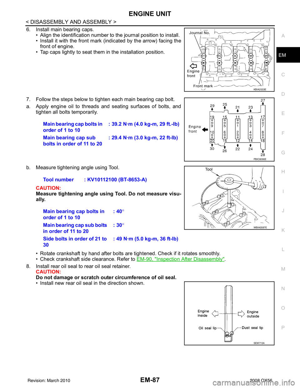
• Align the identification number to the journal position to install.
• Install it with the front mark (indicated by the arrow) facing thefront of engine.
• Tap caps lightly to seat them in the installation position.
7. Follow the steps below to tighten each main bearing cap bolt.
a. Apply engine oil to threads and seating surfaces of bolts, and tighten all bolts temporarily.
b. Measure tightening angle using Tool. CAUTION:
Measure tightening angle usin g Tool. Do not measure visu-
ally.
• Rotate crankshaft by hand after bolts are tightened. Check if it rotates smoothly.
• Check crankshaft side clearance. Refer to EM-90, "
Inspection After Disassembly".
8. Install rear oil seal to rear oil seal retainer. CAUTION:
Do not damage or scratch ou ter circumference of oil seal.
• Install new rear oil seal in the direction shown.
KBIA2533E
Main bearing cap bolts in
order of 1 to 10 : 39.2 N·m (4.0 kg-m, 29 ft.-lb)
Main bearing cap sub
bolts in order of 11 to 20 : 29.4 N·m (3.0 kg-m, 22 ft-lb)
PBIC0090E
Tool number : KV10112100 (BT-8653-A)
Main bearing cap bolts in
order of 1 to 10 : 40
°
Main bearing cap sub bolts
in order of 11 to 20 : 30
°
Side bolts in order of 21 to
30 : 49 N·m (5.0 kg-m, 36 ft-lb)
WBIA0597E
SEM715A
Revision: March 2010
2008 QX56
Page 1924 of 4083

PRECAUTIONSEX-3
< PRECAUTION >
C
DE
F
G H
I
J
K L
M A
EX
NP
O
5. When the repair work is completed, return the ignition switch to the
″LOCK ″ position before connecting
the battery cables. (At this time, the steering lock mechanism will engage.)
6. Perform a self-diagnosis check of al l control units using CONSULT-III.
Precaution for Liquid GasketINFOID:0000000001538868
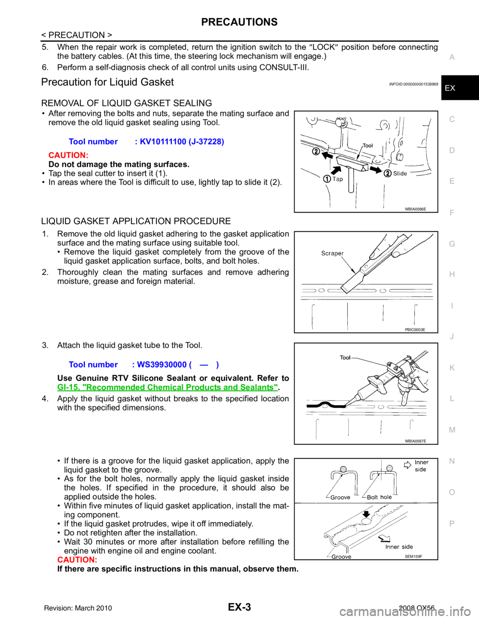
REMOVAL OF LIQUID GASKET SEALING
• After removing the bolts and nuts, separate the mating surface and
remove the old liquid gasket sealing using Tool.
CAUTION:
Do not damage the mating surfaces.
• Tap the seal cutter to insert it (1).
• In areas where the Tool is difficult to use, lightly tap to slide it (2).
LIQUID GASKET APPLICATION PROCEDURE
1. Remove the old liquid gasket adhering to the gasket application surface and the mating surface using suitable tool.
• Remove the liquid gasket completely from the groove of the
liquid gasket application surface, bolts, and bolt holes.
2. Thoroughly clean the mating surfaces and remove adhering moisture, grease and foreign material.
3. Attach the liquid gasket tube to the Tool. Use Genuine RTV Silicone Sealant or equivalent. Refer to
GI-15, "
Recommended Chemical Products and Sealants".
4. Apply the liquid gasket without breaks to the specified location with the specified dimensions.
• If there is a groove for the liquid gasket application, apply theliquid gasket to the groove.
• As for the bolt holes, normally apply the liquid gasket inside
the holes. If specified in the procedure, it should also be
applied outside the holes.
• Within five minutes of liquid gasket application, install the mat-
ing component.
• If the liquid gasket protrudes, wipe it off immediately.
• Do not retighten after the installation.
• Wait 30 minutes or more after installation before refilling the engine with engine oil and engine coolant.
CAUTION:
If there are specific instructions in this manual, observe them.
Tool number : KV10111100 (J-37228)
WBIA0566E
PBIC0003E
Tool number : WS39930000 ( — )
WBIA0567E
SEM159F
Revision: March 2010
2008 QX56
Page 1930 of 4083

EXL-2
HEADLAMP (HI) CIRCUIT ................................28
Description ........................................................... ...28
Component Function Check ...................................28
Diagnosis Procedure ..............................................28
HEADLAMP (LO) CIRCUIT ...............................30
Description ........................................................... ...30
Component Function Check ...................................30
Diagnosis Procedure ..............................................30
FRONT FOG LAMP CIRCUIT ...........................32
Description ........................................................... ...32
Component Function Check ...................................32
Diagnosis Procedure ..............................................32
PARKING LAMP CIRCUIT ................................34
Description ........................................................... ...34
Component Function Check ...................................34
Diagnosis Procedure ..............................................34
TURN SIGNAL LAMP CIRCUIT ........................37
Description ........................................................... ...37
Component Function Check ...................................37
Diagnosis Procedure ..............................................37
OPTICAL SENSOR ...........................................40
Description ..............................................................40
Component Function Check ...................................40
Diagnosis Procedure ..............................................40
HEADLAMP AIMING SWITCH ..........................42
Description ........................................................... ...42
Diagnosis Procedure ..............................................42
HEADLAMP .......................................................43
Wiring Diagram .................................................... ...43
DAYTIME LIGHT SYSTEM ................................47
Wiring Diagram .................................................... ...47
AUTO LIGHT SYSTEM ......................................54
Wiring Diagram .................................................... ...54
HEADLAMP AIMING SYSTEM (MANUAL) ......61
Wiring Diagram .................................................... ...61
FRONT FOG LAMP SYSTEM ...........................65
Wiring Diagram .................................................... ...65
TURN SIGNAL AND HAZARD WARNING
LAMP SYSTEM .............................................. ...
68
Wiring Diagram .................................................... ...68
PARKING, LICENSE PLATE AND TAIL
LAMPS SYSTEM ............................................ ...
75
Wiring Diagram .................................................... ...75
STOP LAMP ......................................................81
Wiring Diagram .................................................... ...81
BACK-UP LAMP ................................................85
Wiring Diagram .................................................... ...85
TRAILER TOW ..................................................90
Wiring Diagram .................................................... ...90
ECU DIAGNOSIS .......................................99
BCM (BODY CONTROL MODULE) ............... ...99
Description ........................................................... ...99
IPDM E/R (INTELLIGENT POWER DISTRI-
BUTION MODULE ENGINE ROOM) ................
100
Description ........................................................... .100
SYMPTOM DIAGNOSIS ...........................101
EXTERIOR LIGHTING SYSTEM SYMPTOMS ..101
Symptom Table .................................................... .101
NORMAL OPERATING CONDITION ...............103
Description ........................................................... .103
BOTH SIDE HEADLAMPS DO NOT SWITCH
TO HIGH BEAM ................................................
104
Description ........................................................... .104
Diagnosis Procedure .............................................104
BOTH SIDE HEADLAMPS (LO) ARE NOT
TURNED ON .....................................................
105
Description ............................................................105
Diagnosis Procedure .............................................105
PARKING, LICENSE PLATE AND TAIL
LAMPS ARE NOT TURNED ON ......................
106
Description ........................................................... .106
Diagnosis Procedure .............................................106
BOTH SIDE FRONT FOG LAMPS ARE NOT
TURNED ON .....................................................
107
Description ............................................................107
Diagnosis Procedure .............................................107
PRECAUTION ...........................................108
PRECAUTIONS .............................................. ..108
Precaution for Supplemental Restraint System
(SRS) "AIR BAG" and "SEAT BELT PRE-TEN-
SIONER" .............................................................. .
108
Precaution Necessary for Steering Wheel Rota-
tion After Battery Disconnect ................................
108
ON-VEHICLE REPAIR ..............................110
ADJUSTMENT AND INSPECTION ................ ..110
HEADLAMP ............................................................ .110
HEADLAMP : Aiming Adjustment .........................110
FRONT FOG LAMP ................................................ .111
FRONT FOG LAMP : Aiming Adjustment .............111
REMOVAL AND INSTALLATION .............113
HEADLAMP .................................................... ..113
Revision: March 2010 2008 QX56
Page 2059 of 4083

EXT-6
< SERVICE INFORMATION >
SQUEAK AND RATTLE TROUBLE DIAGNOSES
If the noise can be duplicated easily during the test drive, to help identify the source of the noise, try to dupli-
cate the noise with the vehicle stopped by doing one or all of the following:
1) Close a door.
2) Tap or push/pull around the area where the noise appears to be coming from.
3) Rev the engine.
4) Use a floor jack to recreate vehicle “twist”.
5) At idle, apply engine load (electrical load, half-clutch on M/T model, drive position on A/T model).
6) Raise the vehicle on a hoist and hit a tire with a rubber hammer.
• Drive the vehicle and attempt to duplicate the conditions the customer states exist when the noise occurs.
• If it is difficult to duplicate the noise, drive the v ehicle slowly on an undulating or rough road to stress the
vehicle body.
CHECK RELATED SERVICE BULLETINS
After verifying the customer concern or symptom, chec k ASIST for Technical Service Bulletins (TSBs) related
to that concern or symptom.
If a TSB relates to the symptom, follo w the procedure to repair the noise.
LOCATE THE NOISE AND IDENTIFY THE ROOT CAUSE
1. Narrow down the noise to a general area.To help pinpoint the source of the noise, use a listening tool
(Chassis Ear: J-39570, Engine Ear: J-39565 and mechanic's stethoscope).
2. Narrow down the noise to a more specific area and identify the cause of the noise by:
• removing the components in the area that you suspect the noise is coming from.
Do not use too much force when removing clips and fasteners, otherwise clips and fasteners can be broken
or lost during the repair, resulting in the creation of new noise.
• tapping or pushing/pulling the component that you suspect is causing the noise.
Do not tap or push/pull the component with excessive force, otherwise the noise will be eliminated only tem-
porarily.
• feeling for a vibration with your hand by touching the component(s) that you suspect is (are) causing the
noise.
• placing a piece of paper between components that you suspect are causing the noise.
• looking for loose components and contact marks. Refer to EXT-7, "
Generic Squeak and Rattle Troubleshooting".
REPAIR THE CAUSE
• If the cause is a loose component, tighten the component securely.
• If the cause is insufficient clearance between components:
- separate components by repositioning or loos ening and retightening the component, if possible.
- insulate components with a suitable insulator such as urethane pads, foam blocks, felt cloth tape or urethane tape. A NISSAN Squeak and Rattle Kit (J-43980) is av ailable through your authorized NISSAN Parts Depart-
ment.
CAUTION:
Do not use excessive force as many components are constructed of plastic and may be damaged.
Always check with the Parts Department for the latest parts information.
The following materials are contained in the NISSAN Squeak and Rattle Kit (J-43980). Each item can be
ordered separately as needed.
URETHANE PADS [1.5 mm (0.059 in) thick]
Insulates connectors, harness, etc.
76268-9E005: 100 ×135 mm (3.94× 5.31 in)/76884-71L01: 60 ×85 mm (2.36 ×3.35 in)/76884-71L02: 15 ×25
mm (0.59× 0.98 in)
INSULATOR (Foam blocks)
Insulates components from contact. Can be used to fill space behind a panel.
73982-9E000: 45 mm (1.77 in) thick, 50 ×50 mm (1.97 ×1.97 in)/73982-50Y00: 10 mm (0.39 in) thick,
50× 50 mm (1.97 ×1.97 in)
INSULATOR (Light foam block)
80845-71L00: 30 mm (1.18 in) thick, 30 ×50 mm (1.18 ×1.97 in)
FELT CLOTH TAPE
Used to insulate where movemen t does not occur. Ideal for instrument panel applications.
68370-4B000: 15 ×25 mm (0.59× 0.98 in) pad/68239-13E00: 5 mm (0.20 in ) wide tape roll. The following
materials not found in the kit can also be used to repair squeaks and rattles.
UHMW (TEFLON) TAPE
Insulates where slight movement is present. Ideal for inst rument panel applications.
Revision: March 2010 2008 QX56