2008 INFINITI QX56 air condition
[x] Cancel search: air conditionPage 3506 of 4083
STEERING WHEELST-15
< ON-VEHICLE REPAIR >
C
DE
F
H I
J
K L
M A
B
ST
N
O P
ON-VEHICLE REPAIR
STEERING WHEEL
On-Vehicle Inspection and ServiceINFOID:0000000004920096
CHECKING CONDITION OF INSTALLATION
• Check installation condition of steering gear assembly, front suspension, axle and steering column.
• Check if movement exists when steering wheel is mo ved up and down, to the left and right and to the axial
direction.
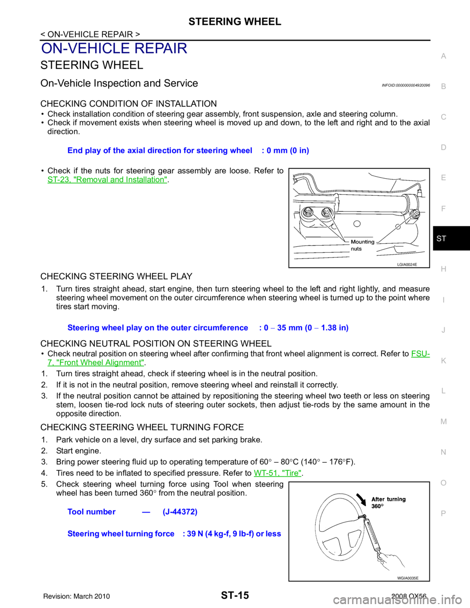
• Check if the nuts for steering gear assembly are loose. Refer to ST-23, "
Removal and Installation".
CHECKING STEERING WHEEL PLAY
1. Turn tires straight ahead, start engine, then turn steer ing wheel to the left and right lightly, and measure
steering wheel movement on the outer circumference when steering wheel is turned up to the point where
tires start moving.
CHECKING NEUTRAL POSITION ON STEERING WHEEL
• Check neutral position on steering wheel after confirming that front wheel alignment is correct. Refer to FSU-
7, "Front Wheel Alignment".
1. Turn tires straight ahead, check if steering wheel is in the neutral position.
2. If it is not in the neutral position, remo ve steering wheel and reinstall it correctly.
3. If the neutral position cannot be attained by repositi oning the steering wheel two teeth or less on steering
stem, loosen tie-rod lock nuts of steering outer socket s, then adjust tie-rods by the same amount in the
opposite direction.
CHECKING STEERING WHEEL TURNING FORCE
1. Park vehicle on a level, dry surface and set parking brake.
2. Start engine.
3. Bring power steering fluid up to operating temperature of 60 ° – 80 °C (140 ° – 176 °F).
4. Tires need to be inflated to specified pressure. Refer to WT-51, "
Tire".
5. Check steering wheel turning force using Tool when steering wheel has been turned 360 ° from the neutral position.
End play of the axial direction
for steering wheel : 0 mm (0 in)
LGIA0024E
Steering wheel play on the outer circumference : 0 − 35 mm (0 − 1.38 in)
Tool number — (J-44372)
Steering wheel turning force : 39 N (4 kg-f, 9 lb-f) or less
WGIA0035E
Revision: March 2010 2008 QX56
Page 3532 of 4083

PRECAUTIONSSTR-3
< PRECAUTION >
C
DE
F
G H
I
J
K L
M A
STR
NP
O
5. When the repair work is completed, return the ignition switch to the
″LOCK ″ position before connecting
the battery cables. (At this time, the steering lock mechanism will engage.)
6. Perform a self-diagnosis check of al l control units using CONSULT-III.
Precaution for Power Generation Variable Voltage Control SystemINFOID:0000000001538874
CAUTION:
For this model, the battery current sensor that is installed to the negative battery cable measures the
charging/discharging current of the battery and performs various engine controls. If an electrical com-
ponent is connected directly to the negative battery terminal, the current flowing through that compo-
nent will not be measured by the battery current sensor. This condition may cause a malfunction of
the engine control system and battery discharge m ay occur. Do not connect an electrical component
or ground wire directly to the battery terminal.
Revision: March 2010 2008 QX56
Page 3540 of 4083
S CONNECTOR CIRCUITSTR-11
< COMPONENT DIAGNOSIS >
C
DE
F
G H
I
J
K L
M A
STR
NP
O
S CONNECTOR CIRCUIT
DescriptionINFOID:0000000001696230
Terminal "1" (S) is the power supply for the starter mo
tor magnetic switch. Terminal 1 is supplied with power
when the ignition switch is turned to the START position while the selector lever is in the P or N position.
Diagnosis ProcedureINFOID:0000000001696231
CAUTION:
Perform diagnosis under the cond ition that engine cannot start by the following procedure.
1. Remove fuel pump fuse.
2. Crank or start the engine (where possi ble) until the fuel pressure is released.
1.CHECK STARTER MOTOR MAGNETIC SWITCH CIRCUIT
1. Turn ignition switch OFF.
2. Disconnect starter motor connector F28.
3. Shift transmission into park or neutral.
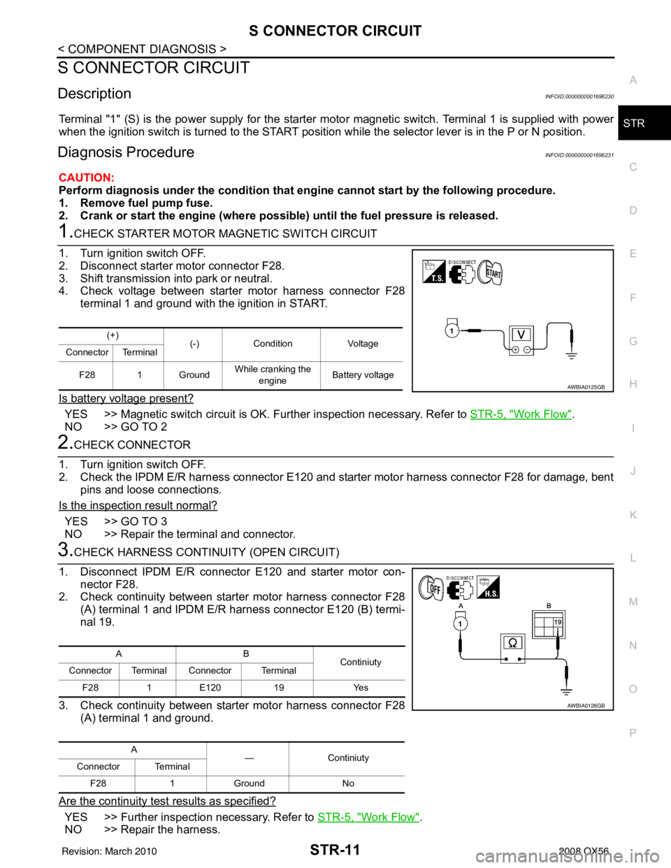
4. Check voltage between starter motor harness connector F28 terminal 1 and ground with the ignition in START.
Is battery voltage present?
YES >> Magnetic switch circuit is OK. Further inspection necessary. Refer to STR-5, "Work Flow".
NO >> GO TO 2
2.CHECK CONNECTOR
1. Turn ignition switch OFF.
2. Check the IPDM E/R harness connector E120 and starter motor harness connector F28 for damage, bent pins and loose connections.
Is the inspection result normal?
YES >> GO TO 3
NO >> Repair the terminal and connector.
3.CHECK HARNESS CONTI NUITY (OPEN CIRCUIT)
1. Disconnect IPDM E/R connector E120 and starter motor con- nector F28.
2. Check continuity between starter motor harness connector F28 (A) terminal 1 and IPDM E/R harness connector E120 (B) termi-
nal 19.
3. Check continuity between starter motor harness connector F28 (A) terminal 1 and ground.
Are the continuity test results as specified?
YES >> Further inspection necessary. Refer to STR-5, "Work Flow".
NO >> Repair the harness.
(+) (-)Condition Voltage
Connector Terminal
F28 1 Ground While cranking the
engine Battery voltage
AWBIA0125GB
AB
Continiuty
Connector Terminal Connector Terminal
F28 1E120 19 Yes
A —Continiuty
Connector Terminal
F28 1Ground No
AWBIA0126GB
Revision: March 2010 2008 QX56
Page 3552 of 4083
DIAGNOSIS AND REPAIR WORKFLOWTM-5
< BASIC INSPECTION >
CEF
G H
I
J
K L
M A
B
TM
N
O P
BASIC INSPECTION
DIAGNOSIS AND REPAIR WORKFLOW
Work FlowINFOID:0000000001603985
INTRODUCTION
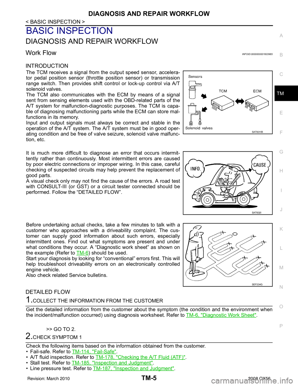
The TCM receives a signal from the output speed sensor, accelera-
tor pedal position sensor (throttle position sensor) or transmission
range switch. Then provides shift c ontrol or lock-up control via A/T
solenoid valves.
The TCM also communicates with the ECM by means of a signal
sent from sensing elements used wit h the OBD-related parts of the
A/T system for malfunction-diagnostic purposes. The TCM is capa-
ble of diagnosing malfunctioning parts while the ECM can store mal-
functions in its memory.
Input and output signals must always be correct and stable in the
operation of the A/T system. T he A/T system must be in good oper-
ating condition and be free of valve seizure, solenoid valve malfunc-
tion, etc.
It is much more difficult to diagnose an error that occurs intermit-
tently rather than continuously. Most intermittent errors are caused
by poor electric connections or impr oper wiring. In this case, careful
checking of suspected circuits may help prevent the replacement of
good parts.
A visual check only may not find t he cause of the errors. A road test
with CONSULT-III (or GST) or a circuit tester connected should be
performed. Follow the “DETAILED FLOW”.
Before undertaking actual checks, take a few minutes to talk with a
customer who approaches with a driveability complaint. The cus-
tomer can supply good information about such errors, especially
intermittent ones. Find out what symptoms are present and under
what conditions they occur. A “Diagnostic work sheet” as shown on
the example (Refer to TM-6
) should be used.
Start your diagnosis by looking for “conventional” errors first. This will
help troubleshoot driveability errors on an electronically controlled
engine vehicle.
Also check related Service bulletins.
DETAILED FLOW
1.COLLECT THE INFORMATION FROM THE CUSTOMER
Get the detailed information from the customer about the symptom (the condition and the environment when
the incident/malfunction occurred) us ing diagnosis worksheet. Refer to TM-6, "
Diagnostic Work Sheet".
>> GO TO 2.
2.CHECK SYMPTOM 1
Check the following items based on the in formation obtained from the customer.
• Fail-safe. Refer to TM-114, "
Fail-Safe".
• A/T fluid inspection. Refer to TM-178, "
Checking the A/T Fluid (ATF)".
• Stall test. Refer to TM-185, "
Inspection and Judgment".
• Line pressure test. Refer to TM-187, "
Inspection and Judgment".
SAT631IB
SAT632I
SEF234G
Revision: March 2010 2008 QX56
Page 3553 of 4083
TM-6
< BASIC INSPECTION >
DIAGNOSIS AND REPAIR WORKFLOW
>> GO TO 3.
3.CHECK DTC
1. Check DTC.
2. Perform the following procedure if DTC is detected.
• Record DTC.
• Erase DTC. Refer to TM-30, "
OBD-II Diagnostic Trouble Code (DTC)".
Is any DTC detected?
YES >> GO TO 4.
NO >> GO TO 6.
4.PERFORM DIAGNOSTIC PROCEDURE
Perform “Diagnosis Procedure” for the displayed DTC.
>> GO TO 5.
5.PERFORM DTC CONFIRMATION PROCEDURE
Perform “DTC CONFIRMATION PROCEDURE”.
Is DTC detected?
YES >> GO TO 4.
NO >> GO TO 6.
6.CHECK SYMPTOM 2
Try to confirm the symptom described by the customer.
Is any malfunction present?
YES >> GO TO 7.
NO >> INSPECTION END
7.ROAD TEST
Perform “ROAD TEST”. Refer to TM-189, "
Description".
>> GO TO 8.
8.CHECK SYMPTOM 3
Try to confirm the symptom described by the customer.
Is any malfunction present?
YES >> GO TO 2.
NO >> INSPECTION END
Diagnostic Work SheetINFOID:0000000001603986
INFORMATION FROM CUSTOMER
KEY POINTS• WHAT ..... Vehicle and A/T model
• WHEN ..... Date, Frequencies
• WHERE ..... Road conditions
• HOW ..... Operating conditions, Symptoms
Customer name MR/MS Model and Year VIN
Trans. Model EngineMileage
Malfunction Date Manuf. DateIn Service Date
Frequency �† Continuous �† Intermittent ( times a day)
Revision: March 2010 2008 QX56
Page 3586 of 4083
P0615 STARTER RELAYTM-39
< COMPONENT DIAGNOSIS >
CEF
G H
I
J
K L
M A
B
TM
N
O P
P0615 STARTER RELAY
DescriptionINFOID:0000000001604014
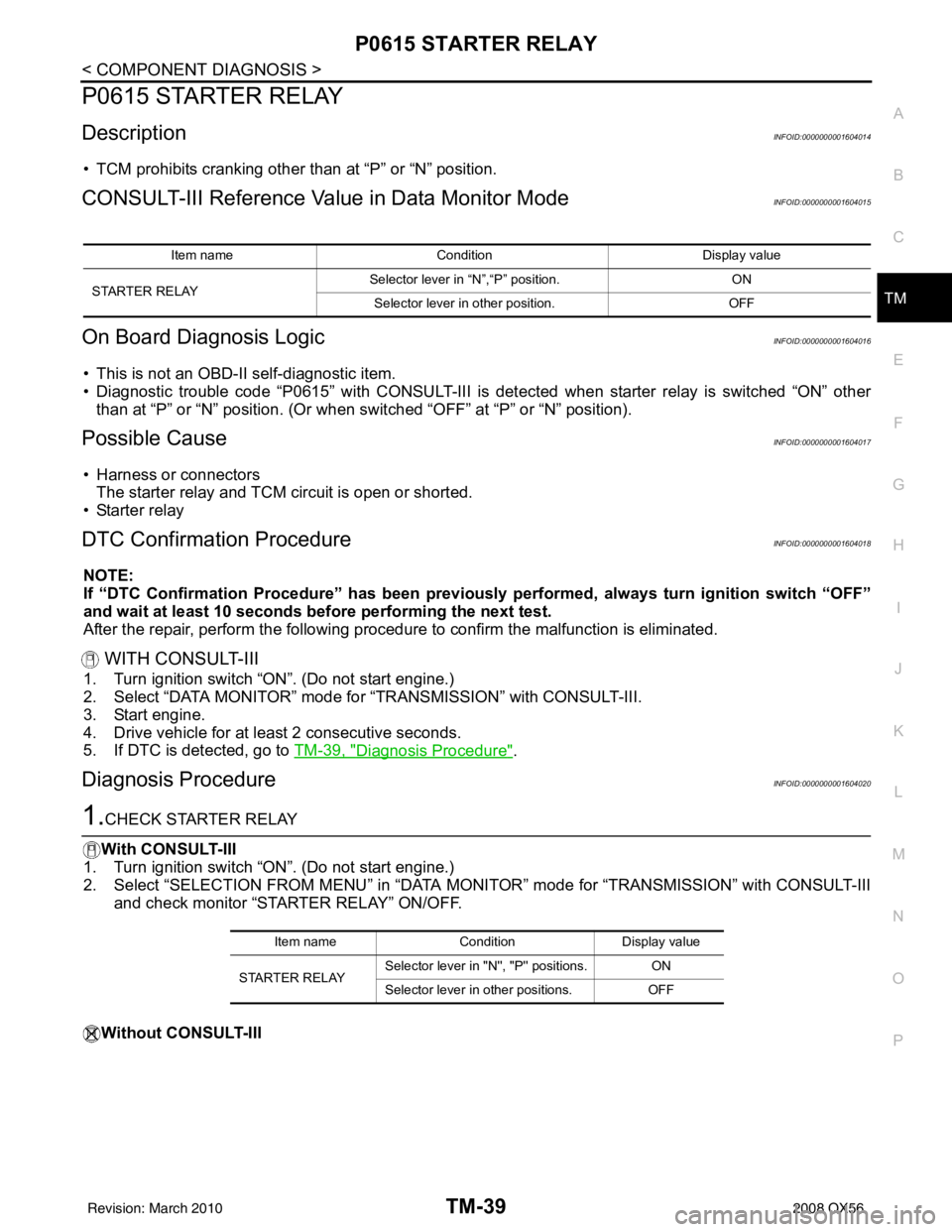
• TCM prohibits cranking other than at “P” or “N” position.
CONSULT-III Reference Val ue in Data Monitor ModeINFOID:0000000001604015
On Board Diagnosis LogicINFOID:0000000001604016
• This is not an OBD-II self-diagnostic item.
• Diagnostic trouble code “P0615” with CONSULT-III is det ected when starter relay is switched “ON” other
than at “P” or “N” position. (Or when s witched “OFF” at “P” or “N” position).
Possible CauseINFOID:0000000001604017
• Harness or connectors
The starter relay and TCM circuit is open or shorted.
•Starter relay
DTC Confirmation ProcedureINFOID:0000000001604018
NOTE:
If “DTC Confirmation Procedure” has been previously performed, always turn ignition switch “OFF”
and wait at least 10 seconds before performing the next test.
After the repair, perform the following procedure to confirm the malfunction is eliminated.
WITH CONSULT-III
1. Turn ignition switch “ON”. (Do not start engine.)
2. Select “DATA MONITOR” mode for “TRANSMISSION” with CONSULT-III.
3. Start engine.
4. Drive vehicle for at least 2 consecutive seconds.
5. If DTC is detected, go to TM-39, "
Diagnosis Procedure".
Diagnosis ProcedureINFOID:0000000001604020
1.CHECK STARTER RELAY
With CONSULT-III
1. Turn ignition switch “ON”. (Do not start engine.)
2. Select “SELECTION FROM MENU” in “DATA MONI TOR” mode for “TRANSMISSION” with CONSULT-III
and check monitor “STARTER RELAY” ON/OFF.
Without CONSULT-III
Item name Condition Display value
STARTER RELAY Selector lever in
“N”,“P” position. ON
Selector lever in other position. OFF
Item nameCondition Display value
STARTER RELAY Selector lever in "N
'', "P'' positions. ON
Selector lever in other positions. OFF
Revision: March 2010 2008 QX56
Page 3590 of 4083
P0705 TRANSMISSION RANGE SWITCH A
TM-43
< COMPONENT DIAGNOSIS >
C EF
G H
I
J
K L
M A
B
TM
N
O P
P0705 TRANSMISSION RANGE SWITCH A
DescriptionINFOID:0000000001604026
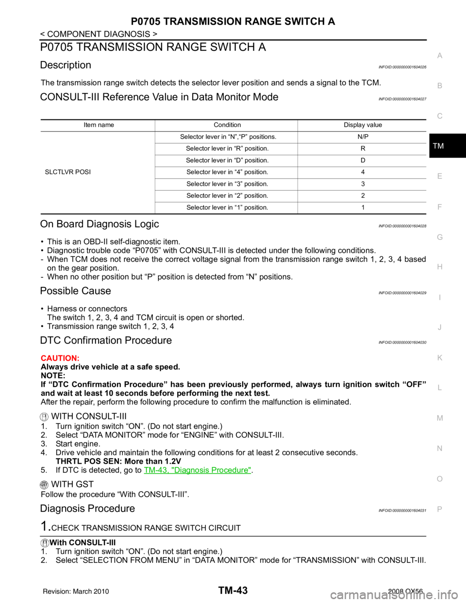
The transmission range switch detects the select or lever position and sends a signal to the TCM.
CONSULT-III Reference Value in Data Monitor ModeINFOID:0000000001604027
On Board Diagnosis LogicINFOID:0000000001604028
• This is an OBD-II self-diagnostic item.
• Diagnostic trouble code “P0705” with CONSULT-III is detected under the following conditions.
- When TCM does not receive the correct voltage signal from the transmission range switch 1, 2, 3, 4 based
on the gear position.
- When no other position but “P” positi on is detected from “N” positions.
Possible CauseINFOID:0000000001604029
• Harness or connectors
The switch 1, 2, 3, 4 and TCM circuit is open or shorted.
• Transmission range switch 1, 2, 3, 4
DTC Confirmation ProcedureINFOID:0000000001604030
CAUTION:
Always drive vehicle at a safe speed.
NOTE:
If “DTC Confirmation Procedure” has been previously performed, always turn ignition switch “OFF”
and wait at least 10 seconds before performing the next test.
After the repair, perform the following procedure to confirm the malfunction is eliminated.
WITH CONSULT-III
1. Turn ignition switch “ON”. (Do not start engine.)
2. Select “DATA MONITOR” mode for “ENGINE” with CONSULT-III.
3. Start engine.
4. Drive vehicle and maintain the following conditions for at least 2 consecutive seconds. THRTL POS SEN: More than 1.2V
5. If DTC is detected, go to TM-43, "
Diagnosis Procedure".
WITH GST
Follow the procedure “With CONSULT-III”.
Diagnosis ProcedureINFOID:0000000001604031
1.CHECK TRANSMISSION RANGE SWITCH CIRCUIT
With CONSULT-III
1. Turn ignition switch “ON”. (Do not start engine.)
2. Select “SELECTION FROM MENU” in “DATA MONI TOR” mode for “TRANSMISSION” with CONSULT-III.
Item nameCondition Display value
SLCTLVR POSI Selector lever in “N”,“P” positions.
N/P
Selector lever in “R” position. R
Selector lever in “D” position. D
Selector lever in “4” position. 4
Selector lever in “3” position. 3
Selector lever in “2” position. 2
Selector lever in “1” position. 1
Revision: March 2010 2008 QX56
Page 3591 of 4083
TM-44
< COMPONENT DIAGNOSIS >
P0705 TRANSMISSION RANGE SWITCH A
3. Check if correct selector lever position (N/P, R or D) is displayed as selector lever is moved into each posi-
tion.
OK or NG
OK >> GO TO 5.
NG >> GO TO 2.
2.CHECK TCM POWER SUPPLY AND GROUND CIRCUIT
Perform TCM power supply and ground circuit. Refer to TM-92, "
Diagnosis Procedure".
OK or NG
OK >> GO TO 3.
NG >> Repair or replace damaged parts.
3.DETECT MALFUNCTIONING ITEM
Check the following items:
• A/T assembly harness connector pin terminals for damage or loose connection with harness connector.
OK or NG
OK >> GO TO 4.
NG >> Repair or replace damaged parts.
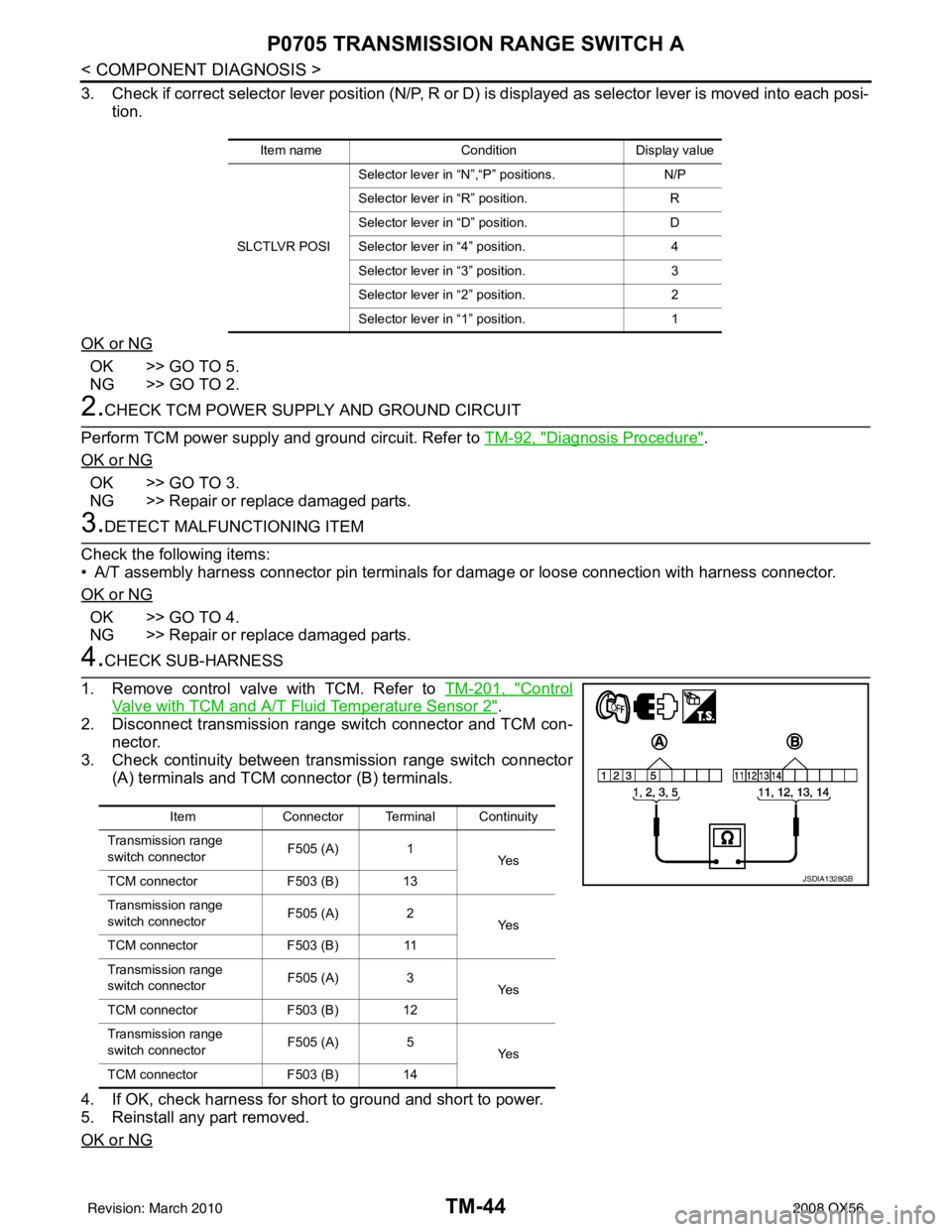
4.CHECK SUB-HARNESS
1. Remove control valve with TCM. Refer to TM-201, "
Control
Valve with TCM and A/T Fluid Temperature Sensor 2".
2. Disconnect transmission range switch connector and TCM con- nector.
3. Check continuity between transmission range switch connector
(A) terminals and TCM connector (B) terminals.
4. If OK, check harness for short to ground and short to power.
5. Reinstall any part removed.
OK or NG
Item name Condition Display value
SLCTLVR POSI Selector lever in “N”,“P” positions.
N/P
Selector lever in “R” position. R
Selector lever in “D” position. D
Selector lever in “4” position. 4
Selector lever in “3” position. 3
Selector lever in “2” position. 2
Selector lever in “1” position. 1
ItemConnector Terminal Continuity
Transmission range
switch connector F505 (A)
1
Ye s
TCM connector F503 (B) 13
Transmission range
switch connector F505 (A)
2
Ye s
TCM connector F503 (B) 11
Transmission range
switch connector F505 (A)
3
Ye s
TCM connector F503 (B) 12
Transmission range
switch connector F505 (A)
5
Ye s
TCM connector F503 (B) 14
JSDIA1328GB
Revision: March 2010 2008 QX56