Page 2973 of 4083
NOISE, VIBRATION AND HARSHNESS (NVH) TROUBLESHOOTINGRAX-5
< SYMPTOM DIAGNOSIS >
CEF
G H
I
J
K L
M A
B
RAX
N
O P
SYMPTOM DIAGNOSIS
NOISE, VIBRATION AND HARSHN ESS (NVH) TROUBLESHOOTING
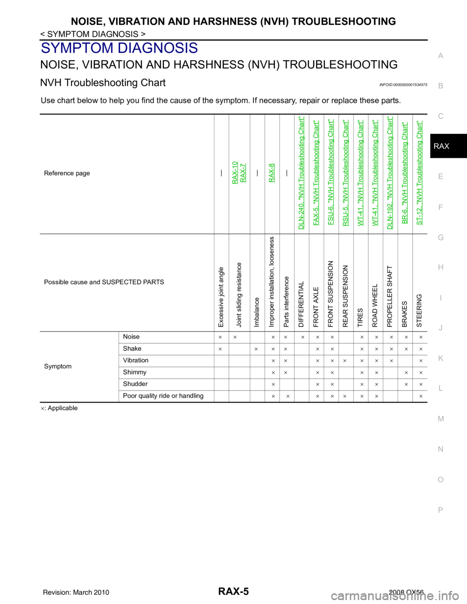
NVH Troubleshooting ChartINFOID:0000000001534575
Use chart below to help you find the cause of the symptom. If necessary, repair or replace these parts.
×: Applicable
Reference page
—
RAX-10RAX-7—
RAX-8—
DLN-240, "
NVH Troubleshooting Chart
"
FAX-5, "
NVH Troubleshooting Chart
"
FSU-6, "
NVH Troubleshooting Chart
"
RSU-5, "
NVH Troubleshooting Chart
"
WT-41, "
NVH Troubleshooting Chart
"
WT-41, "
NVH Troubleshooting Chart
"
DLN-192, "
NVH Troubleshooting Chart
"
BR-6, "
NVH Troubleshooting Chart
"
ST-12, "
NVH Troubleshooting Chart
"
Possible cause and SUSPECTED PARTS
Excessive joint angle
Joint sliding resistance
Imbalance
Improper installation, looseness
Parts interference
DIFFERENTIAL
FRONT AXLE
FRONT SUSPENSION
REAR SUSPENSION
TIRES
ROAD WHEEL
PROPELLER SHAFT
BRAKES
STEERING
Symptom Noise
×× ×× ××× ×××××
Shake × × ×× ×× ×××××
Vibration ×× ××× ××× ×
Shimmy ×× ×× ×× ××
Shudder × ××××××
Poor quality ride or handling ×× ××× ×× ×
Revision: March 2010 2008 QX56
Page 3042 of 4083
PRECAUTIONSRSU-3
< PRECAUTION >
C
DF
G H
I
J
K L
M A
B
RSU
N
O P
5. When the repair work is completed, return the ignition switch to the ″LOCK ″ position before connecting
the battery cables. (At this time, the steering lock mechanism will engage.)
6. Perform a self-diagnosis check of al l control units using CONSULT-III.
Precaution for Rear SuspensionINFOID:0000000001534647
• When installing the rubber bushings, the final tightening must be done under unladen condition and with the
tires on level ground. Oil will shorten the life of the rubber bushings, so wipe off any spilled oil immediately.
• Unladen condition means the fuel tank, engine coolant and lubricants are at the full specification. The spare
tire, jack, hand tools, and mats are in their designated positions.
• After installing suspension components, check the wheel alignment.
• Caulking nuts are not reusable. Always use new caulking nuts for installation. New caulking nuts are pre- oiled, do not apply any additional lubrication.
Revision: March 2010 2008 QX56
Page 3044 of 4083
NOISE, VIBRATION AND HARSHNESS (NVH) TROUBLESHOOTINGRSU-5
< SYMPTOM DIAGNOSIS >
C
DF
G H
I
J
K L
M A
B
RSU
N
O P
SYMPTOM DIAGNOSIS
NOISE, VIBRATION AND HARSHN ESS (NVH) TROUBLESHOOTING
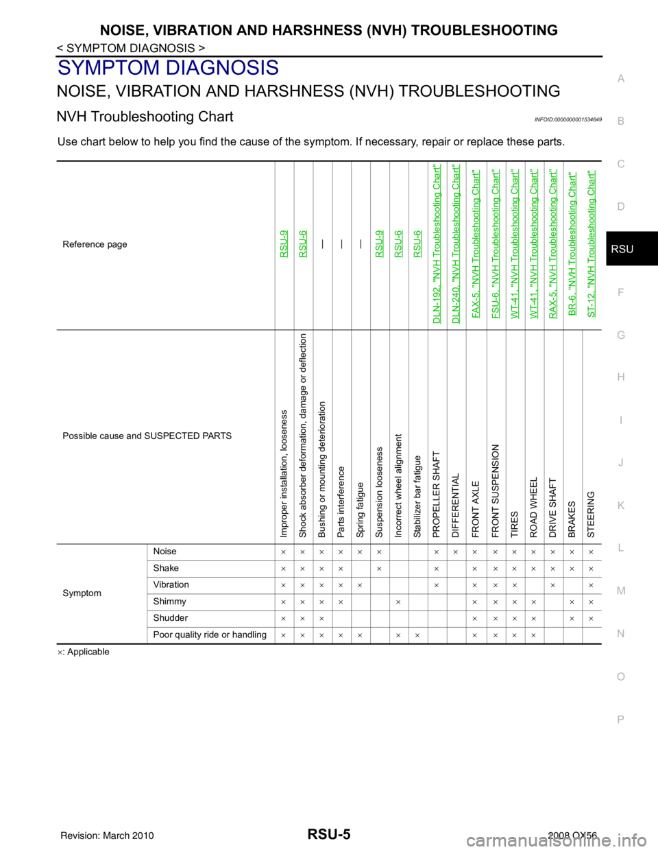
NVH Troubleshooting ChartINFOID:0000000001534649
Use chart below to help you find the cause of the symptom. If necessary, repair or replace these parts.
×: ApplicableReference page
RSU-9RSU-6—
—
—
RSU-9RSU-6RSU-6
DLN-192, "
NVH Troubleshooting Chart
"
DLN-240, "
NVH Troubleshooting Chart
"
FAX-5, "
NVH Troubleshooting Chart
"
FSU-6, "
NVH Troubleshooting Chart
"
WT-41, "
NVH Troubleshooting Chart
"
WT-41, "
NVH Troubleshooting Chart
"
RAX-5, "
NVH Troubleshooting Chart
"
BR-6, "
NVH Troubleshooting Chart
"
ST-12, "
NVH Troubleshooting Chart
"
Possible cause and SUSPECTED PARTS
Improper installation, looseness
Shock absorber deformation, damage or deflection
Bushing or mounting deterioration
Parts interference
Spring fatigue
Suspension looseness
Incorrect wheel alignment
Stabilizer bar fatigue
PROPELLER SHAFT
DIFFERENTIAL
FRONT AXLE
FRONT SUSPENSION
TIRES
ROAD WHEEL
DRIVE SHAFT
BRAKES
STEERING
Symptom Noise
×××××× ××× ××××××
Shake ×××× × × × ××××××
Vibration ××××× × × ×× × ×
Shimmy ×××× × × ××× ××
Shudder ××× × ××× ××
Poor quality ride or handling ××××× ×× × ×××
Revision: March 2010 2008 QX56
Page 3045 of 4083
RSU-6
< ON-VEHICLE MAINTENANCE >
REAR SUSPENSION ASSEMBLY
ON-VEHICLE MAINTENANCE
REAR SUSPENSION ASSEMBLY
On-Vehicle Inspection and ServiceINFOID:0000000001534667
Check all of the component mountings for any excessive looseness, or back lash. Check the components for
any excessive wear, damage, or abnormal conditions. Repair or replace the components as necessary.
SHOCK ABSORBER INSPECTION
• Check the shock absorbers for any air leaks or damage, and replace as necessary.
• Check the hoses for any air leaks or damage, and replace as necessary.
Wheel Alignment InspectionINFOID:0000000001534668
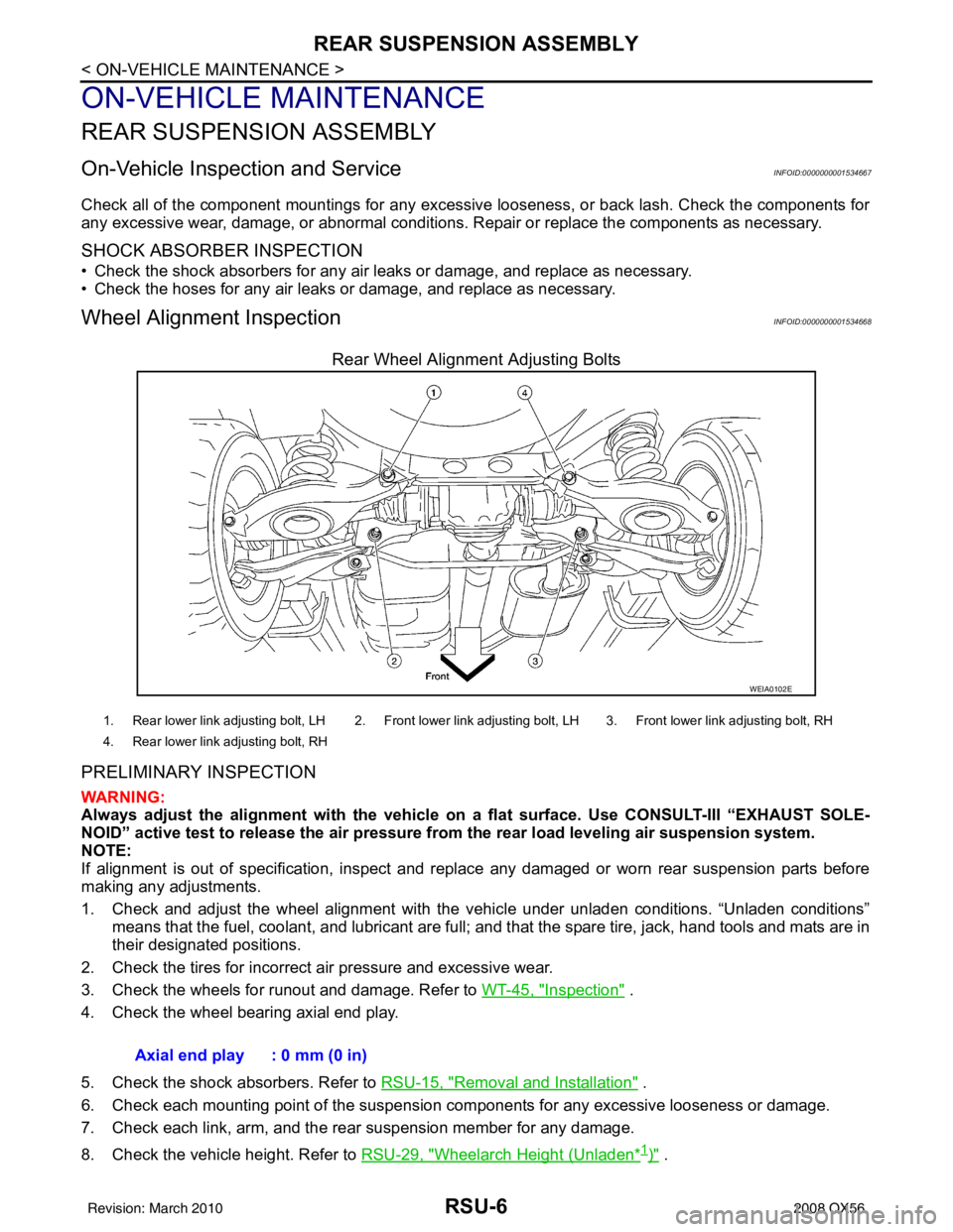
Rear Wheel Alignment Adjusting Bolts
PRELIMINARY INSPECTION
WARNING:
Always adjust the alignment with the vehicle on a flat surface. Use CONSULT-III “EXHAUST SOLE-
NOID” active test to release the air pressure from the rear load leveling air suspension system.
NOTE:
If alignment is out of specificat ion, inspect and replace any damaged or worn rear suspension parts before
making any adjustments.
1. Check and adjust the wheel alignment with the vehicle under unladen conditions. “Unladen conditions”
means that the fuel, coolant, and lubricant are full; and that the spare tire, jack, hand tools and mats are in
their designated positions.
2. Check the tires for incorrect air pressure and excessive wear.
3. Check the wheels for runout and damage. Refer to WT-45, "
Inspection" .
4. Check the wheel bearing axial end play.
5. Check the shock absorbers. Refer to RSU-15, "
Removal and Installation" .
6. Check each mounting point of the suspension components for any excessive looseness or damage.
7. Check each link, arm, and the rear suspension member for any damage.
8. Check the vehicle height. Refer to RSU-29, "
Wheelarch Height (Unladen*1)" .
WEIA0102E
1. Rear lower link adjusting bolt, LH 2. Front lower link adjusting bolt, LH 3. Front lower link adjusting bolt, RH
4. Rear lower link adjusting bolt, RH
Axial end play : 0 mm (0 in)
Revision: March 2010 2008 QX56
Page 3047 of 4083
RSU-8
< ON-VEHICLE MAINTENANCE >
REAR SUSPENSION ASSEMBLY
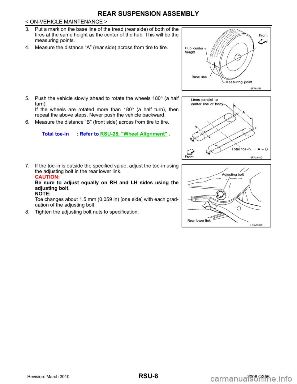
3. Put a mark on the base line of the tread (rear side) of both of the
tires at the same height as the center of the hub. This will be the
measuring points.
4. Measure the distance “A” (rear side) across from tire to tire.
5. Push the vehicle slowly ahead to rotate the wheels 180 ° (a half
turn).
If the wheels are rotated more than 180° (a half turn), then
repeat the above steps. Never push the vehicle backward.
6. Measure the distance “B” (front side) across from tire to tire.
7. If the toe-in is outside the specified value, adjust the toe-in using the adjusting bolt in the rear lower link.
CAUTION:
Be sure to adjust equally on RH and LH sides using the
adjusting bolt.
NOTE:
Toe changes about 1.5 mm (0.059 in) [one side] with each grad-
uation of the adjusting bolt.
8. Tighten the adjusting bolt nuts to specification.
SFA614B
Total toe-in : Refer to RSU-28, "Wheel Alignment" .
SFA234AC
LEIA0009E
Revision: March 2010 2008 QX56
Page 3053 of 4083
RSU-14
< REMOVAL AND INSTALLATION >
REAR SUSPENSION MEMBER
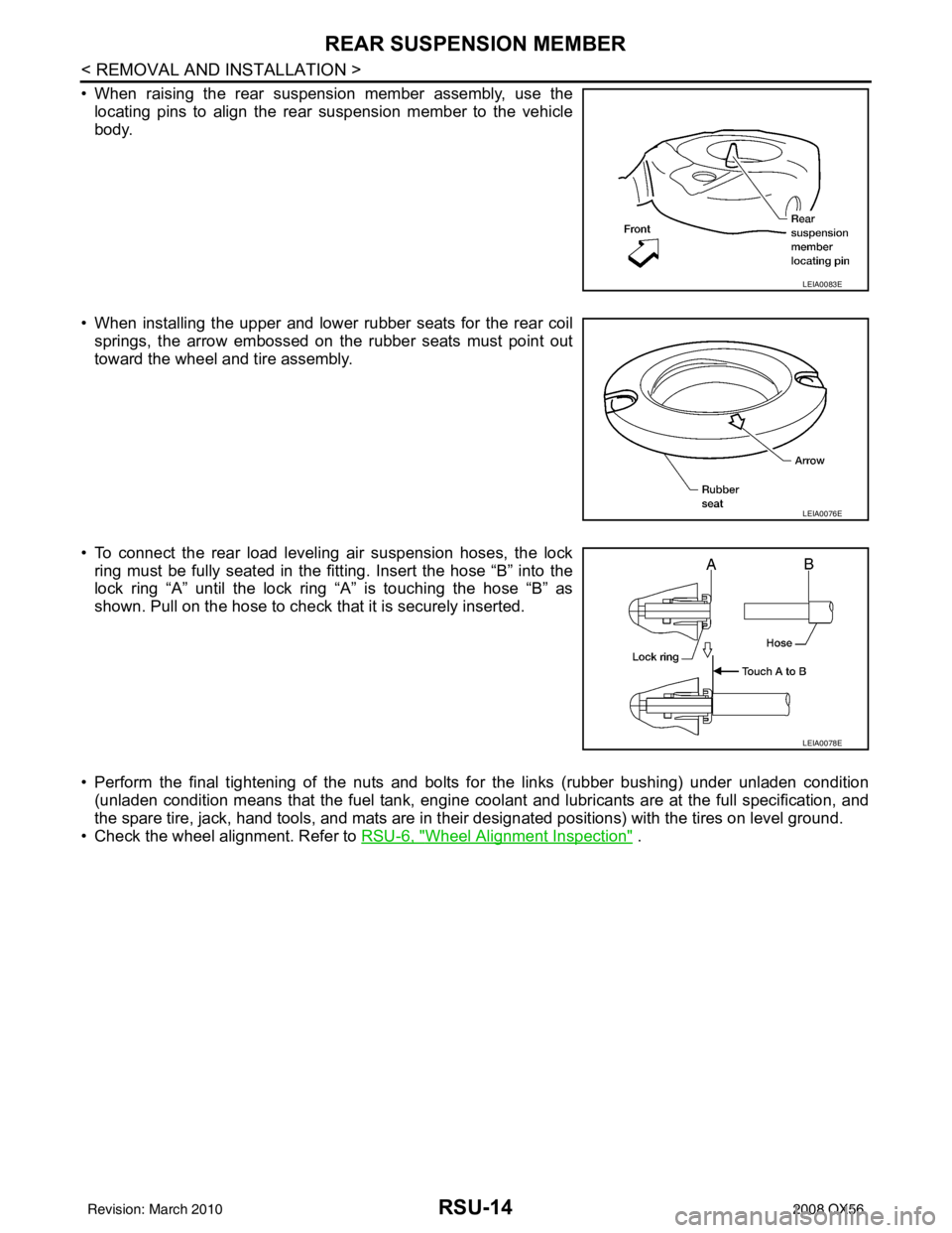
• When raising the rear suspension member assembly, use thelocating pins to align the rear suspension member to the vehicle
body.
• When installing the upper and lower rubber seats for the rear coil springs, the arrow embossed on the rubber seats must point out
toward the wheel and tire assembly.
• To connect the rear load leveling air suspension hoses, the lock ring must be fully seated in the fitt ing. Insert the hose “B” into the
lock ring “A” until the lock ring “A” is touching the hose “B” as
shown. Pull on the hose to check that it is securely inserted.
• Perform the final tightening of the nuts and bolts for the links (rubber bushing) under unladen condition (unladen condition means that the fuel tank, engine cool ant and lubricants are at the full specification, and
the spare tire, jack, hand tools, and mats are in t heir designated positions) with the tires on level ground.
• Check the wheel alignment. Refer to RSU-6, "
Wheel Alignment Inspection" .
LEIA0083E
LEIA0076E
LEIA0078E
Revision: March 2010 2008 QX56
Page 3056 of 4083
SUSPENSION ARMRSU-17
< REMOVAL AND INSTALLATION >
C
DF
G H
I
J
K L
M A
B
RSU
N
O P
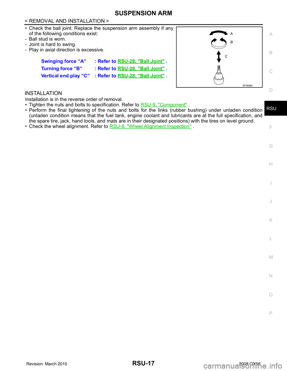
• Check the ball joint. Replace the suspension arm assembly if any of the following conditions exist:
- Ball stud is worn.
- Joint is hard to swing.
- Play in axial direction is excessive.
INSTALLATION
Installation is in the reverse order of removal.
• Tighten the nuts and bolts to specification. Refer to RSU-9, "
Component" .
• Perform the final tightening of the nuts and bolts for the links (rubber bushing) under unladen condition
(unladen condition means that the fuel tank, engine cool ant and lubricants are at the full specification, and
the spare tire, jack, hand tools, and mats are in t heir designated positions) with the tires on level ground.
• Check the wheel alignment. Refer to RSU-6, "
Wheel Alignment Inspection" .
Swinging force “A” : Refer to RSU-28, "
Ball Joint" .
Turning force “B” : Refer to RSU-28, "
Ball Joint" .
Vertical end play “C” : Refer to RSU-28, "
Ball Joint" .
SFA858A
Revision: March 2010 2008 QX56
Page 3058 of 4083
FRONT LOWER LINKRSU-19
< REMOVAL AND INSTALLATION >
C
DF
G H
I
J
K L
M A
B
RSU
N
O P
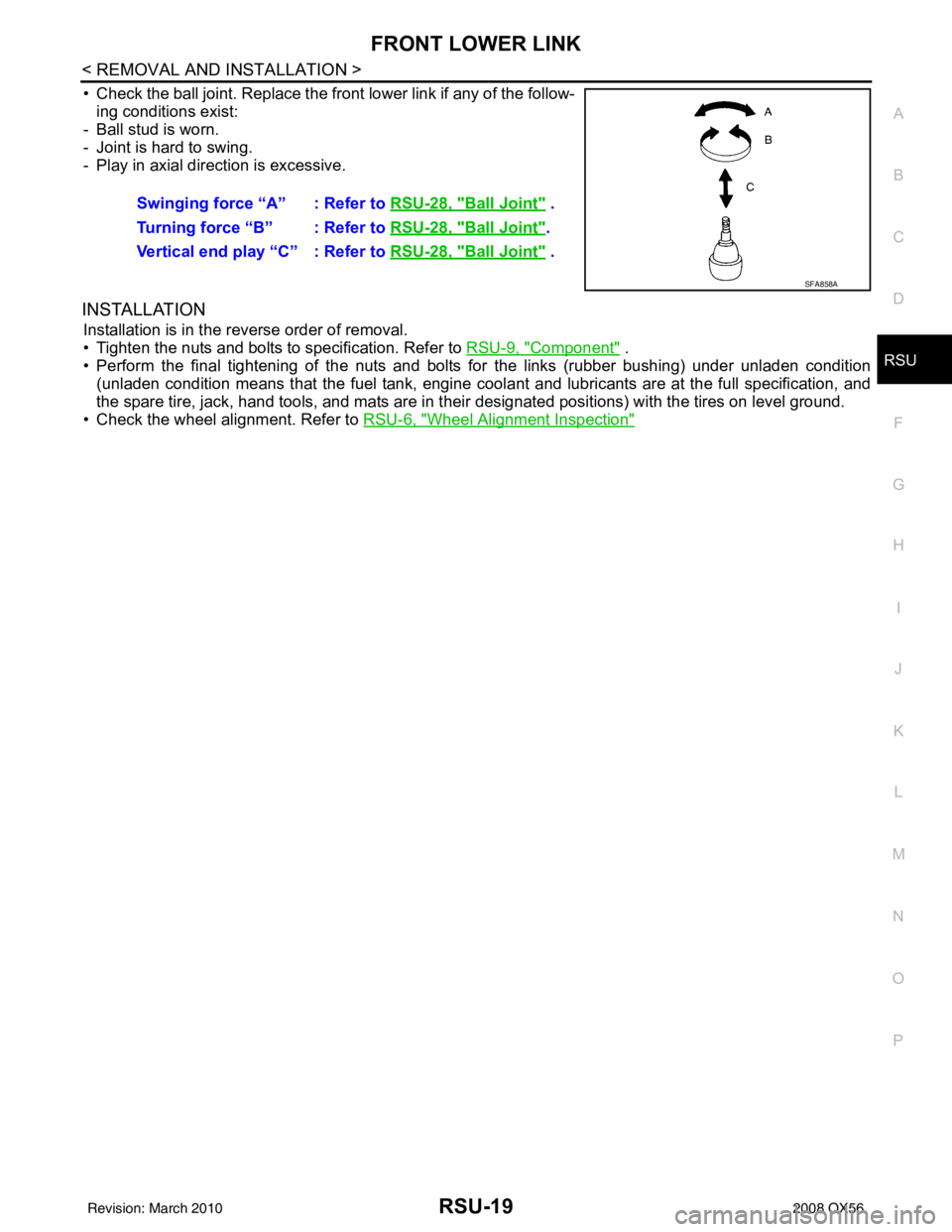
• Check the ball joint. Replace the front lower link if any of the follow- ing conditions exist:
- Ball stud is worn.
- Joint is hard to swing.
- Play in axial direction is excessive.
INSTALLATION
Installation is in the reverse order of removal.
• Tighten the nuts and bolts to specification. Refer to RSU-9, "
Component" .
• Perform the final tightening of the nuts and bolts for the links (rubber bushing) under unladen condition
(unladen condition means that the fuel tank, engine cool ant and lubricants are at the full specification, and
the spare tire, jack, hand tools, and mats are in t heir designated positions) with the tires on level ground.
• Check the wheel alignment. Refer to RSU-6, "
Wheel Alignment Inspection"
Swinging force “A” : Refer to RSU-28, "Ball Joint" .
Turning force “B” : Refer to RSU-28, "
Ball Joint".
Vertical end play “C” : Refer to RSU-28, "
Ball Joint" .
SFA858A
Revision: March 2010 2008 QX56